An efficient area utilization of FM0/Manchester Encoding Using
SOLS Technique
Junaid Muddassir & Syed Alihussain
(M.Tech Scholar) 1(Assistant Professor)2 Electronics and Communication Engineering Department1,2 1,2NIMRA Institute of Science and Technology , India.
1[email protected] 2[email protected]
Abstract
:
The dedicated short-rangecommunication (DSRC) is an emerging technique to push the intelligent transportation system into our daily life. The DSRC standards generally adopt FM0 and Manchester codes to reach dc-balance, enhancing the signal reliability. Nevertheless, the coding-diversity between the FM0 and Manchester codes seriously limits the potential to design a fully reused VLSI architecture for both. In this paper, the similarity-oriented logic simplification (SOLS) technique is proposed to overcome this limitation. The SOLS technique improves the hardware utilization rate for both FM0 and Manchester encodings. The encoding capability of this paper can fully support the DSRC standards of America, Europe, and Japan. This paper not only develops a fully reused VLSI architecture, but also exhibits an efficient performance compared with the existing works.
I INTRODUCTION
As the scale of integration keeps growing, more and more sophisticated signal processing systems are being implemented on a VLSI chip. These signal processing applications not only demand great computation capacity but also consume considerable amount of energy. While performance and Area remain to be the two major design tolls, power consumption has become a critical concern in today’s VLSI system design. The need for low-power VLSI system arises from
two main forces. First, with the steady growth of operating frequency and processing capacity per chip, large currents have to be delivered and the heat due to large power consumption must be removed by proper cooling techniques. Second, battery life in portable electronic devices is limited. Low power design directly leads to prolonged operation time in these portable devices. Encoding techniques are becoming more important in communication. Techniques such as Manchester and FM0 encoding can be used in various applications. Each technique has different operations based on their needs. Each encoding scheme should be used without losing any of its parameters. The finite state machine can be used for all encodings, because at a time the input has given the corresponding output can be occurred due to this. So speed can be increased. The fully-reused VLSI architecture of FM0 and Manchester encoders has reduced the number of transistors and maintains the DC balance.
Manchester code is easily a galvanically isolator (it is the principle of isolating functional sections of electric systems to prevent current flow) using a network isolator for simple one-to-one isolation transformation.
II LITERATURE SURVEY
The dedicated short-range communication (DSRC) is a protocol for one- or two-way medium range communication especially for intelligent transportation systems. The DSRC can be briefly classified into two categories: to-automobile and to-to-roadside. In to- automobile-to-automobile, the DSRC enables the message sending and broadcasting among automobiles for safety issues and public information announcement .
The safety issues include blind-spot,
intersection warning, inter cars distance, and collision-alarm. The automobile-to-roadside focuses on the intelligent transportation service, such as electronic toll collection (ETC) system. With ETC, the toll collecting is electrically accomplished with the contactless IC-card platform. Moreover, the ETC can be extended to the payment for parking-service, and gas-refueling. Thus, the DSRC system plays an important role in modern automobile
industry. The system architecture of DSRC transceiver is shown in Fig. The upper and bottom parts are dedicated for transmission and receiving, respectively. This transceiver is classified into three basic modules: microprocessor, baseband processing, and RF front-end.
Fig.1. System architecture of DSRC transceiver.
III EXISTING SYSTEM
Fig.2 Hardware architecture of FM0 and Manchester encodings
Coding principles of fm0 code and Manchester
code
In the following discussion, the clock signal and the input data are abbreviated as CLK, and X, respectively. With the above parameters, the coding principles of FM0 and Manchester codes are discussed as follows.
A. FM0 Encoding As shown in Fig. 2, for each X, the FM0 code consists of two parts: one for former-half cycle of CLK, A, and the other one for later-half cycle of CLK,B. The coding principle of FM0 is listed as the following three rules.
1) If X is the logic-0, the FM0 code must exhibit a transition between A and B.
2) If X is the logic-1, no transition is allowed between A and B.
3) The transition is allocated among each FM0 code no matter what the X is.
Fig.3 Illustration of FM0 coding example.
Fig.4 Illustration of Manchester coding example.
IV PROPOSED SYSTEM
The purpose of SOLS technique is to design a fully reused VLSI architecture for FM0 and Manchester encodings. The SOLS technique is classified into two parts: area-compact retiming and balance logic-operation sharing. Each part is individually described as follows. Finally, the performance evaluation of the SOLS technique given.
Area-compact retiming
Fig.5. FM0 encoding
Without area compact retiming
The FM0 logic in Fig 5 is simply shown in
Fig.6 The logic for A(t) and the logic for B(t) are
the Boolean functions to derive A(t) and B(t),
where the X is omitted for a concise
representation. For FM0, the state code of each
state is stored into DFFA and DFFB. According to
(2) and (3), the transition of state code only
depends on B(t − 1) instead of both A(t − 1) and
B(t − 1). Thus, the FM0 encoding just requires a
single 1-bit flip-flop to store the B(t−1). If the
DFFA is directly removed, a non synchronization
between A(t) and B(t) causes the logic fault of
FM0 code. To avoid this logic-fault, the DFFB is
relocated right after the MUX−1, as shown in Fig.6
where the DFFB is assumed to be positive-edge
triggered. At each cycle, the FM0 code, comprising
A and B, is derived from the logic of A(t) and the
logic of B(t), respectively. The FM0 code is
alternatively switched between A(t) and B(t)
through the MUX−1 by the control signal of the
CLK. In Fig6 the Q of DFFB is directly updated
from the logic of B(t) with 1-cycle latency.in fig.6
when the CLK is logic-0, the B(t) is passed
through MUX−1 to the D of DFFB.
Fig.6 FM0 encoding with area compact retiming
Balance logic-operation sharing
This can be realized by the multiplexer, as shown
in Fig.7.
Fig.7 Manchester encoding with multiplexer
It is quite similar to the Boolean function of
FM0 encoding in (4). By comparing with (4) and
(6), the FM0 and Manchester logics have a
common point of the multiplexer like logic with
the selection of CLK. As shown in 8, the concept
of balance logic-operation sharing is to integrate
the
𝑋
into A(t) and X into B(t), respectively.
Fig.8 Combine the logic operation of FMO and Manchester encoding
The logic for A(t)/𝑋 is shown in Fig.9. The
A(t) can be derived from an inverter of B(t − 1), and 𝑋
is obtained by an inverter of X. The logic for A(t)/𝑋 can
share the same inverter, and then a multiplexer is placed before the inverter to switch the operands of B(t − 1) and X.
Fig9. Balance logic operation sharing of A(t) and 𝑿
The Mode indicates either FM0 or Manchester encoding is adopted. The similar concept can be also applied to the logic for B(t)/X, as shown in Fig.4.7. Nevertheless, this architecture exhibits a drawback that the XOR is only dedicated for FM0 encoding, and is not shared with Manchester encoding. Therefore, the HUR of this architecture is certainly limited. The X can
be also interpreted as the X XOR 0, and thereby the
XOR operation can be shared with Manchester and FM0 encodings. As a result, the logic for B(t)/X is shown in Fig.11, where the multiplexer is responsible to switch the operands of B(t−1) and logic-0.
.
Fig 10. Balanced logic operation sharing of B(t) and X without xor sharing
Fig.11 Balanced logic operation with XOR sharing
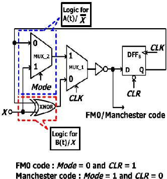
This architecture shares the XOR for both B(t) and X, and thereby increases the HUR. Furthermore, the multiplexer in Fig. 4.8 can be functionally integrated into the relocated DFFB from area-compact retiming technique, as shown in Fig.13. The CLR is the clear signal to reset the content of DFFB to logic-0. The DFFB can be set to zero by activating CLR for Manchester encoding. When the FM0 code is adopted, the CLR is disabled, and the B(t −1) can be derived from DFFB.
Fig.13 Unbalance computation time between A(t)/𝑋
and B(t)/X using SOLS technique
Fig .14.Balance computation time between A(t)/
𝑋
and B(t)/X using SOLS technique
The logic for A(t)/
𝑋
includes the MUX−2
and an inverter. Instead, the logic for B(t)/X just
incorporates a XOR gate. In the logic for A(t)/
𝑋
,
the computation time of MUX−2 is almost
identical to that of XOR in the logic for B(t)/X.
However, the logic for A(t)/
𝑋
further incorporates
an inverter in the series of MUX−2. This
unbalance computation time between A(t)/
𝑋
and
B(t)/X results in the glitch to MUX−1, possibly
causing the logic-fault on coding. To alleviate this
unbalance computation time, the architecture of the
balance computation time between A(t)/
𝑋
and
B(t)/X is shown in Fig.
If the CLR is simply derived by inverting
Mode without assigning an individual CLR control
signal, this leads to a conflict between the coding
mode selection and the hardware initialization. To
avoid this conflict, both Mode and CLR are
assumed to be separately allocated to this design
from a system controller. Whether FM0 or
Manchester code is adopted, no logic component
of the proposed VLSI architecture is wasted. Every
component is active in both FM0 and Manchester
encodings. Therefore, the HUR of the proposed
VLSI architecture is greatly improved.
V. EXTENSION
We can get an optimized encoding scheme by replacing those two D flip-flops with a Multi-bit flip-flop. The idea of designing the multi-bit flip-flop arises for power considerations and placement rout-ability effectiveness. Some of them are discussed here: Minimization of dynamic clock power leads the way to merge the single-bit flip-flops and constructed Multi-Bit Flip-Flops. This merging process also has to satisfy the certain area constraint which decreases the total flip-flop area in synchronous design.
Proposed results:
Simulation results:
Area report:
RTL schematic:
Timing report:
Extension results:
Simulation results:
RTL schematic:
VII CONCLUSION
The coding-diversity between FM0 and Manchester encodings causes the limitation on hardware utilization of VLSI architecture design. A limitation analysis on hardware utilization of FM0 and Manchester encodings is discussed in detail. In this paper, the fully reused VLSI architecture using SOLS technique for both FM0 and Manchester encodings is proposed. The SOLS technique eliminates the limitation on hardware utilization by two core techniques: area compact retiming and balance logic-operation sharing.
REFERENCES
[1] Benabes, A. Gauthier, and J. Oksman, “A Manchester code generator running at 1 GHz,” in Proc. IEEE, Int. Conf. Electron., Circuits Syst., vol. 3. Dec. 2003, pp. 1156–1159.
[2] A. Karagounis, A. Polyzos, B. Kotsos, and N. Assimakis, “A 90nm Manchester codegenerator with CMOS switches running at 2.4 GHz and 5 GHz,” in Proc. 16th Int. Conf. Syst., Signals Image Process., Jun. 2009, pp. 1–4.
and Miller encoder,” in Proc. Intell. Inf. Hiding Multimedia Signal Process., Sep. 2009, pp. 538–541.
[4] M. A. Khan, M. Sharma, and P. R. Brahmanandha, “FSM based Manchester encoder for UHF RFID tag emulator,” in Proc. Int. Conf. Comput., Commun. Netw., Dec. 2008, pp. 1–6.
[5] M. A. Khan, M. Sharma, and P. R. Brahmanandha, “FSM based FM0 and Miller encoder for UHF RFID tag emulator,” in Proc. IEEE Adv. Comput. Conf., Mar. 2009, pp. 1317–1322
[6] J.-H. Deng, F.-C. Hsiao, and Y.-H. Lin, “Top down design of joint MODEM and CODEC detection schemes for DSRC coded-FSK systems over high mobility fading channels,” in Proc. Adv. Commun. Technol. Jan. 2013, pp. 98–103.
[7] Yu-Hsuan Lee, Member, IEEE, and Cheng-Wei
Pan, “Fully Reused VLSI Architecture of