Material Characterization Using Ring
Resonator
Amruta Kulkarni
M.E. Student, Dept. of Electronics, A.I.S.S.M.S’s COE, Kennedy Road, Pune, India
ABSTRACT: Material characterization is an important field in microwave engineering since it is employed in various systems and applications ranging from high-speed circuits to satellite and telemetry applications. In this research work, I developed a microstrip-based resonant device i.e. ring resonator which is particularly intended for permittivity measurements of low dielectric constant materials at frequency of 1GHz. Different aqueous glucose concentrations ranging from 0% to 50% of glucose in fixed 100mL of water were taken as MUT(Material Under Test). After fabrication of ring resonator it is tested using VNA and again compared the results with the simulated one. This showed that the ring resonator changes its response according to dielectric constant. That means whenever the dielectric constant of the material changes, there is shift in the frequency with respect to the resonating frequency of the resonator.
KEYWORDS: dielectric constant, S11 parameter, S21 parameter, coupling gap, ring resonator
I. INTRODUCTION
Every material has a unique set of electrical characteristics that are dependent on its dielectric properties. So if these measurements are accurate then it can provide scientists and engineers with valuable information to properly use a material into its specific application from high speed circuits to satellite and telemetry applications. Accurate measurements of these properties enable scientists and engineers to incorporate the material for the suitable application, for more solid designs or to monitor a manufacturing process for improved quality control [1].
The resonance techniques do not have the sweep frequency capability, unlike resonance techniques; the transmission techniques usually have the sweep frequency ability for the measured frequency range. However, resonance techniques are more accurate than transmission techniques, especially in calculating small loss tangent or loss factors, therefore resonance techniques are widely used.
In this paper, the dielectric constant of aqueous glucose samples with different concentrations is found out using basic ring resonator as a sensor. There is a shift in resonant frequency of a resonator when a sample and microwaves interact with each other. This shift in frequency is nothing but dielectric constant of that material or sample [5].
II. RELATED WORK
Several techniques were developed to characterize the dielectric properties of materials. Sushanta Sen, et.al. developed a technique of cavity perturbation for estimating electrical parameters of a material. This method involves the modified cylindrical cavity which was suitable for low dielectric materials only [8]. Serhan Yamaeli, Ali akdagii presented a technique for determining dielectric constant of microwave PCB substrates. In this method, a bandpass microstrip filter was used and designed on PCB substrate [6].
Kumar, G. Singh found out a new technique to measure dielectric constant using rectangular shaped cavity [2]. Surendar R developed a method to find out dielectric characterization using meander resonator sensor. This sensor was implemented using planar microstrip technique. Sompain Seewathanopon also developed a microstrip ring resonator for dielectric constant measurement [7].
III.PROPOSED METHOD
A. Structure of Ring resonator:
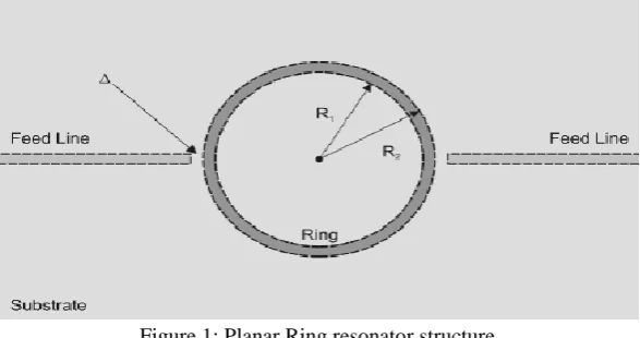
Figure 1: Planar Ring resonator structure
This structure consists of transmission lines and a ring on a substrate. The feed lines and ring resonator are printed transmission lines with width chosen for 50 Ω characteristic impedance. There is a small coupling gap of
between these transmission lines and a ring. The structure of ring resonator is shown in figure 1.B. Design of Ring Resonator:
Here I have designed a ring resonator with FR4 epoxy substrate at 1Ghz resonant frequency. Ring resonators are coupled through a gap to the microstrip line, satisfying the resonance condition:
2
R
n
g for n=1,2,3…….. eq. (1)Here, R is the mean radius of the ring and n is the harmonic order of resonance. Guided wavelength is calculated by using following relation:
g
eff
c
f
eq. (2)Here,
gis the guided wavelength and
eff is the effective dielectric constant and it is given by the relation of1
1
1
2
2
1 12
r r
eff
d
w
eq. (3)
Inner and outer radius of the ring are computed by subtraction and addition of half of width of microstrip to the mean radius resp. It is given by,
Inner radius:
2
i
w
R
R
eq. (4)Outer radius:
2
a
w
R
R
eq. (5)Table 1: Dimensions of Ring resonator Parameters Values
Width of feed line 1 mm
Feed line length 42.86 mm
Coupling gap 0.2 mm
Total length of substrate 141.7 mm
Total width of substrate 115 mm
Inner radius of ring 26.79 mm
Outer radius of ring 27.79 mm
Substrate used FR4
IV.SIMULATION RESULTS
For measuring dielectric constants in this work, ring resonator as a sensor has been designed and simulated in HFSS. Simulation result of ring resonator without MUT is shown in figure 2. First resonance occurs at 0.944GHz with S21 of -8.22dB. Then second , third, resonances at 1.8GHz , 2.81GHz with S21 of -6.40dB and -3.52dB and so on. S21 parameter is shown below in figure 2.
Figure 2: S21 parameter
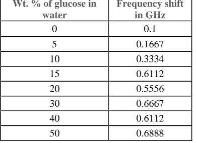
Above graph shows HFSS simulation without MUT on the ring resonator. But for different glucose concentrations different results of simulation are obtained and those are given in tabular form as follows:
Table 2: Relation between aqueous glucose concentration and frequency shift Wt. % of glucose in
water
Frequency shift in GHz
0 0.1
5 0.1667
10 0.3334
15 0.6112
20 0.5556
30 0.6667
40 0.6112
V. EXPERIMENTALRESULTS
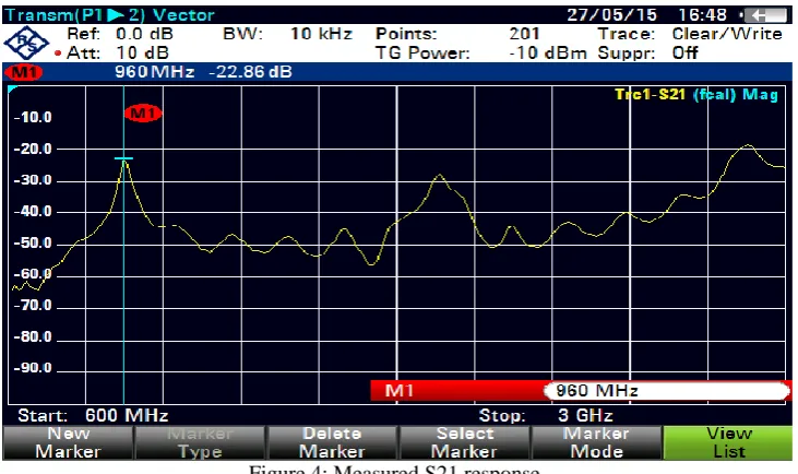
The following figure 3 shows the test set-up of ring resonator using VNA. The ring resonator is tested using Vector Network Analyzer of 8GHz. The measured S21 response of resonator tested using VNA is at 960MHz and is of -22.86dB.
Figure 3: Test set-up
The tested S21 response using VNA is shown in figure 4. The measured response gives -22.86dB at 960MHz.
Figure 4: Measured S21 response
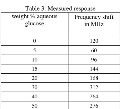
Table 3: Measured response weight % aqueous
glucose
Frequency shift in MHz
0 120
5 60
10 96
15 144
20 168
30 312
40 264
50 276
There is a shift in frequency as per the change in aqueous glucose concentration. This is nothing but the material characterization.
VI.CONCLUSION AND FUTURE WORK
A simple ring resonator as a sensor is designed and simulated in HFSS software and fabricated and tested using VNA. The geometrical parameters are optimized to attain the best electromagnetic properties. This sensor operates at 1GHz frequency and shows good insertion loss which occurs at -8.26dB. Also there is a shift in frequency as aqueous glucose concentration changes due to change in dielectric constant. This shows that a ring resonator can be used as a sensor.
Impending opportunity of this research work will be designing a sensor which should be able to detect these changes , without making direct contact to blood i.e. for non-invasive blood glucose monitoring.
REFERENCES.
1. Surendar R, “Dielectric Characterization using Meander Resonator sensor,” International Journal of Research in Engg & Advanced
Technology, Volume 1, Issue 3 June-July, 2013.
2. Cyrus G. Malmberg, “Dielectric Constants of Aqueous Solutions of Dextrose and Sucrose,” Journal of Research of the National Bureau of
Standards, Vol. 45, No. 4, October 1950.S.K.
3. Muhammad Taha Jilani, “Microstrip Ring Resonator Based Sensing Technique for Meat Quality” In Proceedings of the IEEE Symposium
on Wireless Technology and Applications (ISWTA), pp. 22-25, 2013.
4. S. Yamaeli, C. Ozdemir, A. Akdagli, “A Method for Determining the Dielectric Constant of Microwave PCB Substrate”, Int.J. Infrared
Milli Waves 2008.
5. S. Seewathanopon, P. Akkaraekthalin, “Dielectric Constant Detection by using a new Microstrip Ring Resonator System”, International
Symposium on Antennas and Propagation ISAP 2009.
6. K. Sarabandi, E.S. Li, “Microstrip Ring Resonator for Soil Moisture Measurements”, IEEE Transaction On Geosciences And Remote
Sensing, Vol. 35, No. 5, 1997.
7. H. Fang, D. Linton, C. Walker, B. Collins, “Dielectric Constant Characterization using a Numerical Method for the Microstrip Ring
Resonator” Microwave and optical technology Letters, Vol. 41, N0. 1, 2004.
BIOGRAPHY