Precise Control of Angular Position of Geared
DC Motors for Low Cost Applications
Hannibal Paul 1, Sunitha Lasrado 2
P.G. Student, Department of Electronics and Communication Engineering, NMAMIT, Nitte, Karnataka, India1
Assistant Professor, Department of Electronics and Communication Engineering, NMAMIT, Nitte, Karnataka, India 2
ABSTRACT:Precise control of angular position are very crucial for robotic applications. This however leaves hobbyists with no other choice but to choose between a stepper motor, which has a slow response and a servo motor, which draws a lot of current even when idle and requires a complex control signal. This paper proposes a new technique of combining the existing low cost geared DC motor with the IR sensor to form a closed loop system to provide a precise angular position with high torque and comparatively reduced current.
KEYWORDS:DC motors, Angular position control, Robotics I. INTRODUCTION
Precise angular position control have become very popular these days in various applications including robotics. One of such actuator which provides angular position control is servo motors. Servos have become extremely popular with robotics. Their precise positioning makes them ideal for actuatingjoints in the robots, steering system with rack and pinion, and to control rudder or a thruster to a particular position to name a few. Most of the servo motors can be controlled to rotate for about 90 to 180 degrees. However, servos can't continually rotate which makes them incapable for driving wheels. The servo current drawn is unpredictable [1]. It suddenly draws a huge amount of current to reach the desired angle. Moreover, servo motors are expensive. They become more and more expensive as their output torque increases.
Geared DC motors on the other hand, can provide high torque. The torque generated at the output shaft of a DC motor can be scaled up or scaled down by using a gear train. In most of the motors, the gear train scales up the torque of the motor by using a reduction gearing that outputs a much higher torque at the cost of reduced RPM. The problem with DC motors is that when they have a voltage applied across its terminals, they tend to rotate forever in a particular direction, stopping or reversing the motor can only be achieved by turning off the electric supply or reversing the polarity respectively. In a DC Motor, speed control can be achieved by varying the terminal voltage but position control of the shaft cannot be achieved.
In the proposed system, the high torque advantage of the geared DC motor and precise angular position control of servo motor are combined to form a new type of motor which can be easily affordable by hobbyists at low price. This can be achieved by fitting an encoder to a geared DC motor to provide a feedback loop.
Optical encoders have been widely used in many of the sophisticated applications including robotics for position feedback [2]. In the proposed system an IR transmitter receiver pair is fitted onto the body of a geared DC motor, to detect the number of rotation of the primary shaft and hence provide a feedback to control the output shaft. The output shaft can be easily used in any of the motor applications.
II. RELATED WORK
The rotary encoders are classified into 2 types [6], incremental encoders and absolute encoders. The incremental encoders generates a train of pulses as it displaces from the reference position. The incremental encoders are simpler but gives relative displacement only. Whereas absolute position encoder give absolute positional value, but are complex.
Some of the implemented shaft encoder systems uses a potentiometer or an optical encoder as the feedback element [2] [9] fitted at the end of the output shaft of the motor and [8] at the back shaft of the motor,whichneeds space for a disc which takes up some space hence making it difficult to be used in all applications.Paper [7] uses state space technique.
III.DESIGN OF THE CONTROL SYSTEM
WORKING PRINCIPLE
In a conventional servo, the motor is attached by gears to a potentiometer. The position of the potentiometer changes as the motor rotates, hence the movement and the direction can be regulated precisely by the control circuit [3]. The servo position signal is sent using PWM through the control line. The motor is rotated in the appropriate direction until the shaft is at the desired position.
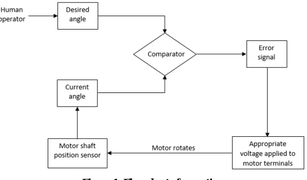
The designed system contains a simple set-up of a geared DC motor and an IR transmitter and receiver, which can be easily interfaced with any type of microcontroller. In order to control the shaft position of a geared DC motor and thereby convert it into a servo motor, the shaft position is required to be encoded to provide a feedback loop. The current position will be compared against desired position and a positional error signal will be generated. Appropriate polarity voltage is applied to the motor terminals to make the positional error zero, as illustrated in Figure 1.
Figure 1: Flow chart of operation
Geared motors are primarily used for reducing the speed using a series of gears, thereby increasing the torque. The gear with the smaller radius rotates faster than the one with larger radius. However, larger gears provide more torque to smaller gear than vice versa. The direction of rotation of gears is always opposite to the one adjacent to it [4]. RPM and torque are inversely proportional to each other in a DC motor. Hence the gear having lower RPM will provide more torque and vice versa. The equation detailing the torque transfer of gears is as shown in (1).
= (1)
where,
ωin = angular speed of the driver gear Tout = output torque of the driven gear ωout = angular speed of the driven gear
The feedback loop can be easily achieved by attaching an IR transmitter and receiver to the geared DC motor. The IR transmitter and receiver is coupled to the primary shaft of a geared DC motor. The primary shaft of the DC motor will be rotating at a much higher rate compared to the output shaft of the motor with the gear train. The IR sensor will generate a pulse for each rotation of the primary shaft, which can be used with a counter to obtain the current position of the motor output shaft. This value will then be fed into the feedback loop allowing the software on a microcontroller to control the angular position of the motor shaft.
CONSTRUCTION
The infrared transmitter and receiver pair consists of an IR LED and a photo diode. The transmitted signal from the IR LEDis detected at the photo diode by reflecting from the surface of an object [5]. Hence an object can be easily detected.
To form a feedback loop for the shaft position of a geared DC motor, IR transmitter receiver pair is fittedonto the gear box of a geared DC motor as shown in Figure 2. Both the IR LED and photo diode are placed facing in the same direction. The primary motor shaft is painted black except for a part of it. When the unpainted region comes in front of IR pair, the IR light gets reflected from the motor shaft and isdetected by the photodiode. When the black region comes in contact it will absorb all the IR light, instead of reflecting it.The IR transmitter receiver pair should be positioned such that a beam of IR light from the IR LED should reach the photo diode by reflecting from the primary shaft the DC motor.
Figure 2: Positioning the IR transmitter and receiver into the primary shaft
The positioning of the IR transmitter and receiveris very important. The transmitter and the receiver must be placed such that the rotationof the motor shaft is detected correctly taking the directivity of the sensor into consideration, which is ± 45 degrees [5]. The directivityand placement of the sensor is as shown in Figure 3.
The maximum and minimum value of angle θis given by equation (2). 45°≤ θ ≤90° (2)
IV.EXPERIMENTATION
The testing of the setup was carried out using an Arduino Uno board as a microcontroller. The motor terminals are connected to the digital output pins of the Arduino through the relay driver. The feedback line from the IR receiver is connected to the digital input of the Arduino board.
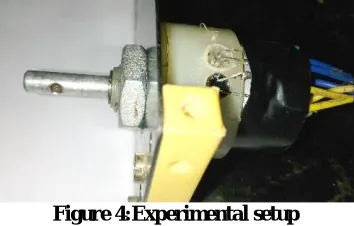
To test the system, the desired angle was read from the keyboard through the serial input of the Arduino. The Arduino compares the desired angle with the current angle. Appropriate signal is sent to the motor driver to rotate the motor shaft in clockwise or anticlockwise direction. The experimentation setup is as shown in Figure 4.
Figure 4:Experimental setup
The motor used in the setup was a 12V geared DC motor of 45 RPM. The primary shaft without the gears connected, had RPM of 3000. So for each rotation of the primary shaft, the output shaft of the geared DC motor rotates for an angle of 5.4 degrees, as calculated from equation (3).
( ) = 360°∗R ℎ
ℎ (3)
As the primary shaft is attached with the gear train, the RPM of the primary shaft reduces slightly. Hence the RPM dropped from 3000 to 2500 approximately. And hence the resolution of output shaft changed to 6.48 degrees. High degrees of resolution can be obtained if ratio of RPM of output shaft to primary shaft is large and hence the torque.
V. COMPARISON
The servo operates the same way as in a DC motor, except that it has a hard to predict feedback control system to contend with [1]. The servo motor will suddenly draw a large amount of current to reach the desired angle, if it is not in that angle already. Also if the servo is made to run at a fixed angle and hang precision weights from the servo horn, the measured current will not be as expected. As the weight increases linearly unpredictable results are obtained, instead of the current increasing at some fixed rate. In conclusion, servo current drawn is unpredictable.
The servo requires a continuous PWM signal of the specified period, to rotate the motor shaft to a required position. Generating a continuous PWM signal cannot be easily achieved by the simpler microcontrollers used to perform other tasks in an application and may require a complex system. And failing to provide a continuous signal will cause servo jitter or vibration.
All the above mentioned limitations of a servo motor can be easily overcome in the proposed system which uses a geared DC motor with simpler drive mechanism and feedback circuit.
Some of the advantages of the proposed system over servo motor are: 1) Simple drive mechanism (PWM not required)
2) Encoder used is IR hence no sensor wear out limits
3) Continuous drive voltage is not required to maintain the same position
4) Predictable current draw hence a simper power supply is sufficient, whereas servo current draw is very unpredictable
5) The motor shaft can rotate in either direction indefinitely 6) Capable of providing high torque and handling heavy loads 7) Inexpensive and can be easily used for small applications
Limitations of the systemare:
1) Torque drops rapidly with speed, if a high RPM motor is used 2) Requirement of a counter at the control circuit
The low cost, high torque and easy to use features allows hobbyists to use the proposed system in numerous applications. Some of the major applications are:
1) Robotics: actuate movements in a robotic arm
2) Camera Auto Focus: A highly precise motor built into the camera positions and corrects the camera's lens 3) Solar Tracking System: To adjust the angle of solar panels throughout the day
4) Conveyor Belts: To move, start, and stop conveyor belts carrying product along to various stages 5) Medical equipment
The designed system is not limited for position control applications but also can be used as any other geared DC motor for continuous rotation.
VI.CONCLUSION
The motor shaft position control is necessary for various applications. The proposed system is capable of providing a precise shaft position control along with high torque feature. It can be built easily using off-the-shelf components as per the requirement, which makes the system inexpensive. And the motor control can be easily achieved without the need for generating sophisticated signals. These features make the proposed system suitable for various low cost applications.
REFERENCES
[1]"How to Build a Robot Tutorials - Society of Robots", Societyofrobots.com, 2016. [Online]. Available: http://www.societyofrobots.com/actuators_servos.shtml. [Accessed: 20- Mar- 2016].
[2]Shashank Wekhande and Vivek Agarwal, “High-Resolution Absolute Position Vernier ShaftEncoder Suitable for High-PerformancePMSM Servo Drives,” IEEE Trans. Instrum. Meas., vol. 55, no. 1,pp. 357-364,February 2006.
[3]Frances Reed, "How Servo Motors Work", Jameco.com, 2016. [Online]. Available: http://www.jameco.com/jameco/workshop/howitworks/how-servo-motors-work.html. [Accessed: 20- Mar- 2016].
[4]Arpit Jain, "How Geared DC Motor works", Engineersgarage.com, 2016. [Online]. Available: http://www.engineersgarage.com/insight/how-geared-dc-motor-works? [Accessed: 21- Mar- 2016].
[5] "IR (Infrared) Obstacle Detection Sensor Circuit", Electronics Hub, 2015. [Online]. Available: http://www.electronicshub.org/ir-sensor/. [Accessed: 21- Mar- 2016].
[6] E. Doebelin, “Measurement systems,” New York: McGraw-Hill, 1975.
[7] A.Chowdhury, D.Debnath,“DCMotor Position Control using State SpaceTechnique,” ISSN 2348-5426 , International Journal of Advancesin Science and Technology (IJAST).
[8] Samadhi Manasa, Swapna Rani T., M. Veda chary, “Position Control of a Dc Motor Using PID Controller,” International Journal of Scientific Engineering and Applied Science (IJSEAS), vol. 1, issue. 3, June 2015