770 |
P a g e
WIRELESS CONTROL OF DC GEARED MOTOR AND
HOME APPLIANCES FROM COMPUTER USING
MICROCONTROLLER
J.N.Rai
1, Rohit Devdhar
2, Utkarsh Sareen
31, 2, 3
Department Of Electrical Engineering, Delhi Technological University, (India)
ABSTRACT
In the present article we have focused for the development of working model on wireless control of dc geared motor and home appliances from computer using AT MEGA 16 microcontroller. Microcontroller is connected to computer using RS232 protocol. A USB to serial convertor (DB9 connector) is used for the connection between computer port and MAX232 [1].COUNTER0 of the microcontroller is used to generate PWM signal. Motor is connected in CHOPPER TYPE-A configuration. Duty cycle of chopper is varied by varying the PWM of the counter generated wave. The speed of the dc geared motor is directly proportional to the duty cycle. Thus by varying duty cycle speed can be varied. PWM generation is controlled by the keys of the computer. For home automation by pressing the key on keyboard of a computer relay status is changed from NO to NC or vice versa. Relays control the home appliances. Through programming it is possible to control both dc geared motor and home appliances simultaneously. Further the attempt has been made to develop this control into a cost effective model.
Keywords: Chopper, Counters, Dutycycle, PWM, Uart.
1. INTRODUCTION
Now a day's every system is automated in order to face new challenges in the present day situation. Automated
systems have lessmanual operations, so that the flexibility, reliabilities are high and accurate. Hence every field
prefers automation and wireless control systems. Wireless home automation has several advantages over control
of home appliances through wire and two-way switches. If we want to control the appliances at a distance of
some meter to several kilometres then cost of wire and losses increases with increase in length. If wireless home
automation is used in place of conventional methods for the control of home appliances then cost of wire and
losses can be reduced. Home automation is necessary to control home appliances wirelessly and accurately. By
using the techniques illustrated in this project we can control the appliances wirelessly and the appliances of a
group of network can be controlled. Motion control plays a vital role in industrial automation. Different types of
motors AC, DC, SERVO or stepper are used depending upon the application. Out of these,Dc geared motors are
widely used because they are easily controllable. Among the different control methods for controlling the speed
771 |
P a g e
speed of Dc geared motor is directly proportional to the voltage applied to its armature winding. The average
voltage across the armature can be controlled by controlling the pulse width [3]. The motor is connected in
chopper type-A configuration. The output voltage is controlled by varying the duty cycle which is controlled
through pulse width modulation.
2. EXPERIMENT COMPONENT
2.1 HARDWARE
1. AT MEGA16 MICROCONTROLLER.
2. COMPUTER.
3. DB9 CONNECTOR
4. MAX232
5. RF MODULE
6. RELAY
7. ULN2803
8. LCD
9. OPTOCOUPLER 4N35
10. MOSFET
11. DC GEARED MOTOR
12. TRANSFORMER (230/12V)
13. IC 7805
14. IC 7812
15. RESISTORS
16. CAPACITORS
17. POTENTIOMETERS.
2.2 SOFTWARE
1. PROTEUS.
2. AVR DUDE
3. EMBEDDED C
4. AVR STUDIO
772 |
P a g e
Fig.1 Block Diagram Of Hardware Module.
IV. HARDWARE DESCRIPTION
1.AT MEGA 16 MICROCONTROLLER: There is a whole wide range of microcontroller available in the
market. But this particular project is developed using AVR series of microcontroller (ATMEGA16). Because of
its inbuilt timer and counter qualities. PWM is generated through TIMER0/COUNTER0 of the microcontroller.
[5]
2. DB9 CONNECTOR: It is 9 pin male/female connector. In DB9 9 represent total number of pins and D
represents the two parallel rows of pins that are in the shape of D alphabet.
3.16*2 LCD: (16*2) have 16 columns and 2 rows. To show the device status whether the appliances are off or
on and to show the dc geared motor speed lcd is used.Lcd may be used in 8-bit mode or bit mode. By using
4-bit mode 4pins of the microcontroller can be saved. Therefore in this project 4-4-bit mode is used.
4. SPDT RELAY: To control the home appliances SPDT relay is used. The rating of relays are(250V, 10A) for
a.c. supply. Relay are controlled by IC ULN2803 which provides 12V signal to relays.
5. ULN2803:The ULN2803A is a high-voltage, high-current Darlington transistor array. The device consists of
eight npn Darlington pairs that feature high-voltage outputs with common-cathode clamp diodes for switching
inductive loads. The collector-current rating of each Darlington pair is 500 mA.
6. OPTOCOUPLER (4N35): an opto-isolator, also called an optocoupler, photo coupler, or optical isolator, is a
component that transfers electrical signals between two isolated circuits by using light. Opto-isolators prevent
high voltage from affecting the system receiving the signal. Optocoupler withstand input-to-output voltages up
to 3.5kVand speed of switching is 7us.
7. MAX232:The MAX232 is a dual driver/receiver that includes a capacitive voltage generator to supply
TIA/EIA-232-F voltage levels from a single 5V supply. Each receiver converts TIA/EIA-232-F inputs to 5-V
TTL/CMOS levels. These receivers have a typical threshold of 1.3 V, a typical hysteresis of 0.5 V, and can
accept ±30-V inputs. Each driver converts TTL/CMOS input levels into TIA/EIA-232-F levels.
8. PMDC: A PMDC GEARED MOTOR of ratings(24V, 2A, 500RPM) is used in this project. Field excitation is
fixed (due to permanent magnet) and the armature voltage is controlled by varying the duty cycle in chopper
type A configuration.
9. RF MODULE (435Mz): An RF module (radio frequency module) is a usually small electronic circuit used to
transmit and receive radio signals on a number of carrier frequencies. Data from the microcontroller is
773 |
P a g e
10. TRANSISTOR (MJE3055T): In this project Transistor is used as a switch. When base signal is high (5V)
then the transistor becomes ON otherwise it remains OFF.
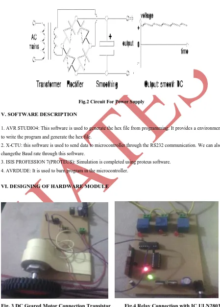
11. POWER SUPLLY:
Fig.2 Circuit For Power Supply
V. SOFTWARE DESCRIPTION
1. AVR STUDIO4: This software is used to generate the hex file from programming. It provides a environment
to write the program and generate the hex file.
2. X-CTU: this software is used to send data to microcontroller through the RS232 communication. We can also
changethe Baud rate through this software.
3. ISIS PROFESSION 7(PROTEUS): Simulation is completed using proteus software.
4. AVRDUDE: It is used to burn program in the microcontroller.
VI. DESIGNING OF HARDWARE MODULE
Fig. 3 DC Geared Motor Connection Transistor
Fig.4 Relay Connection with IC ULN2803
774 |
P a g e
Fig.5 Microcontroller Connection With RF
Fig.6 View Of Complete Hardware
Receiver, LCD and DB9 Connector
Module
VII. SIMULATION DIAGRAM OF THE CIRCUIT
Fig.7 Simulation Diagram Showing All Appliances Are On
775 |
P a g e
8.1 LCD Operation
8.1.1 TO INITIALIZE THE LCD:
voidlcd_init();
{
// This function Initializes the lcd moduleand must be called before calling lcd related functions Arguments:
}
8.1.2. TO SEND COMMAND TO LCD:
voidlcd_command(unsigned char);
{
// This function is used to send command to the lcd.
}
8.1.3. TO SEND DATA TO LCD:
voidlcd_data(unsigned char);
{
// This function is used to send data to lcd.
}
8.1.4. TO SEND STRINGS TO LCD:
voidlcd_string(unsigned char *str);
{
//this function is used to send string of words to lcd.
}
8.1.5. TO SEND A NUMBER TO LCD:
voidlcd_number(unsigned int);
{
// this function is used to send a number to lcd.
}
8.2 UART Operation
8.2.1 TO INITIALIZE THE UART:
voiduart_init();
{
//This function is used to initialize the uart. Baud rate is defined in this function by defining the UBRRH AND
UBRRL registers. Receiving and Transmitting is enabled and mode of operation is also defined in this function.
In this project we are using 8 Bit mode operation.
}
776 |
P a g e
unsigned char uart_rec();
8.2.3 TO SEND A CHARACTER:
voiduart_sendch(unsigned char data);
8.2.4 TO SEND A STRING:
voiduart_sendstr(char *send);
IX. MAIN PROGRAM
#include<avr/io.h>
#define F_CPU 1000000UL
#include<util/delay.h>
#define Baud_Rate 4800UL
#define ubbr_value ((F_CPU/(16UL*Baud_Rate)) - 1)
#include<avr/lcd.h>
#include<avr/uart.h>
int main()
{
TCCR0 |= (1<<WGM00)|(0<<WGM01)|(1<<COM01)|(1<<CS00)|(0<<CS01)|(1<<CS02)|(0<<COM00);
DDRB =0xff;
DDRC=0xff;
unsigned char x;
unsignedint a=0;
DDRC = 0XFF;
lcd_init();
uart_init();
OCR0=0x00;
while(1)
{
x=uart_rec();
if((x=='a')||(x=='A'))
{
lcd_clear();
lcd_command(0x80);
lcd_string("RELAY 1 ON");
777 |
P a g e
}
if((x=='b')||(x=='B'))
{
lcd_clear();
lcd_command(0x80);
lcd_string("RELAY 2 ON");
PORTB=0X02;
}
if((x=='e')||(x=='E'))
{
if(a>=0xfa)
{
a=0xff;
lcd_clear();
lcd_command(0x80);
lcd_string("MOTOR IS RUNNING");
lcd_command(0xc0);
lcd_string("AT FULL SPEED");
}
else
{
a +=0x2a;
lcd_clear();
lcd_command(0x80);
lcd_string("MOTOR SPEED IS");
lcd_command(0xc0);
lcd_string("INCREASING");
}
OCR0=a;
}
return 0;
}
778 |
P a g e
When a key is pressed by the operator on the computer keyboard then using the X-CTU or HYPERTERMINAL
software, binary code corresponding to the key pressed can be send to microcontroller through USB to serial
convertor and IC MAX-232. The output of MAX232 is connected to the microcontroller.
10.1 FOR APPLIANCES CONTROL
When a key is pressed then microcontroller compares the data received at the receiving pin to the condition
given in the programming. On the basis of this condition microcontroller takes a decision. For example if a key
‘a’ is pressed the microcontroller enables the pin PB1. In this way microcontroller remains in the loop or it may
do any other task (interrupt control). As soon as a key is pressed it compares it according to the programming
and if the condition come out to be true then it give a high signal at PB1. The status of the microcontroller
output can be transmitted through RF transmitter. RF receiver receives the signal and its output is connected to
the ULN2803 which is further connected to the RELAY. IC ULN2803 outputis low when its input is high.One
end of relay is connected to the power supply the second end is connected to the output of ULN2803. When
input to the ULN2803 is high then its output become low thus the circuit is completed and current starts
flowing through the relay. Thus normally open (NO) contacts become normally closed (NC). Thus device
connected to the relay become on.
10.2FOR MOTOR CONTROL
The operation of DC geared motor is basically controlled through the pulse width modulation technique. Motor
is connected in chopper type ‘A’ configuration [3]. The motor speed is directly proportional to the voltage
applied to the armature. The average output voltage across the armature depends on the on-off time of the switch
[2]. As key ‘e’ is pressed the motor speed increases because the counter shifts upwards every time,the key ‘e’ is
pressed. When key ‘f’ is pressed the motor speed decreases because the counter shifts downwards every time the
key ‘f’ is pressed.
XI. CHOPPER TYPE-A CONFIGURATION
Fig.8 Chopper Type-A Configuration [2].
Output voltage= a*Vs. …………(1)
779 |
P a g e
Ton is the on time of the switch when a gate pulse is applied. When gate pulse is not applied it remains off. The
gate pulse is given by the microcontroller. By using the counters of microcontroller pulse width can be
controlled. Counters are controlled through programming. Depending upon the key pressed counter will
increment or decrement its value
.
XII. OBSERVATIONS
When key ‘E’ or ‘e’ is pressed then pulse width decreases.
Fig.9when Key ‘E’ Or ‘E’ Is Pressed Then Motor Speed Increase As Pulse Width Increases.
Fig.10 When Key ‘F’ Or ‘F’ Is Pressed Then Motor Speed Decrease As Pulse Width Decreases.
780 |
P a g e
‘C’ or ‘c’ ----Relay 1 and 2 are On.
‘D’ or ‘d’----both Relay1 and Relay 2 are Off. ‘E’ or ‘e’ ----Motor speed increases .
‘F’ or ‘f’----Motor speed decreases. ‘G’ or ‘g’ ----Motor runs at full speed. ‘J’ or ‘j’----Motor stops.
‘I’ or ‘i’ ----Relay 3 On.
‘J’ or ‘j’----Relay 1and 3 are On. ‘K’ or ‘k’ ----Relay 2 and Relay 3 are On. ‘L’ or ‘l’----All Relay are On.
‘Y’ or ‘y’ ----All appliances are On. ‘Z’ or ‘z’----All appliances are Off.
XIII. RESULT
In our working model we have observed that the speed increases on increase in the pulse width and decrease
with decrease in pulse width applied to the gate of switch (as can be seen in simulation). Further by burning the
programme in the microcontroller we have successfully come in a situation to control the width of pulse by
using keyboard. So that by pressing a proper key as per the programme the pulse width can be varied.Hence we
have controlled the speed and direction of dc geared motor via computer using at mega 16 microcontroller.
Secondly we have also successfully controlled home appliances through computer
.
XIV. CONCLUSION
The designing of a sustainable system to control the speed and orientation of a Dc geared motor and to control
the home appliances wirelessly was successfully implemented in this paper.Dc geared motors have speed
control capabilities which means that speed, torque and even direction of rotation can be changed at any time to
meet the new conditions. By using wireless control of home appliances both energy and investment can be
saved. This is a cost effective model also as we can control the dc geared motor and home appliances both from
one microcontroller simultaneously. The paper provides a platform for further advancement in the field of
industrial use of DC geared motors and home automation.
REFERENCES
[1] Jeetender Singh Chauhan, Sunil Semwal / International Journal of Engineering Research and Applications
(IJERA) ISSN: 2248-9622 www.ijera.com Vol. 3, Issue 1, January -February 2013, pp.778-783.
[2] Bimbhra, P.S., Power Electronics. New Delhi, Khanna Publishers, 2006.
[3] Dubey, G.K., Fundamentals of Electrical Drives. New Delhi, Narosa Publishing House, 2009.
[4] M.H.rashid, Power Electronics, Pearson education.