Department of CSE, MCA &CE, Mohandas College of Engineering and Technology, Thiruvananthapuram, Kerala, India
Comparative Study on Static Analyses of a
Box Girder Bridge
Devi Nair M
Department of Civil Engineering, Mohandas College of Engineering and Technology, Thiruvananthapuram,
Kerala, India
ABSTRACT: Finite element analysis is widely used by practicing engineers and researchers in design of bridges.Grillage method of analysis was practiced before the finite element analysis came into prominence. For many years, design of concrete bridge structures has been based on two dimensional frame analysis. Recently three dimensional elements have been employed in finite element analysis. Modelling of various components in the model needs to be given importance. The present study envisages modeling and analysis of a box girderbridge. Modeling of deck is studied in finite element software CSiBridge. The bridge deck is analysed by conventional manual calculations as well as grillage analysis and the results are compared with that of the finite element analysis using shell model. Comparison showed that the values for bending moment and shear force from finite element method gives the lowest value among the three methods making it more economical than the other methods. But the grillage model is easy to construct and use
KEYWORDS: finite element analysis;grillage analogy; CSiBridge;box girder bridge
I. INTRODUCTION
A finite element analysis is a numerical simulation of the behavior of a real-world structure which is intended to provide information that can be used by a designer to ensure a structural design is fit for its intended purpose. The finite element method consists of subdividing the actual structure into a suitable number of sub-regions that are called finite elements. These elements can be in the form of line elements, two dimensional elements or three-dimensional elements to represent the structure. Displacements are the most commonly used nodal variable, with most general purpose programs limiting their nodal degree of freedom to just displacements. A number of displacement functions such as polynomials and trigonometric series can be assumed, especially polynomials because of the ease and simplification they provide in the finite element formulation.
This is an important concept to understand because the focus of the analysis is the real world, which is not a mathematical model. It is, therefore a process that takes an actual structure, subject to its constraints including attachments to other structures. In the past structural analyses were often done with simplified models, for example two-dimensional equivalent beam or frame models. Such a model is not able to describe the distribution of forces in transversal directions.
ISSN (Online) : 2319 - 8753
ISSN (Print) : 2347 - 6710
International Journal of Innovative Research in Science, Engineering and Technology
An ISO 3297: 2007 Certified Organization Volume 5, Special Issue 14, December 2016
3rd National Conference on Recent Trends in ComputerScienceand Engineeringand Sustainability in Civil
Engineering (TECHSYNOD’16)
19th, 20th and 21st December 2016
Organized by
Department of CSE, MCA &CE, Mohandas College of Engineering and Technology, Thiruvananthapuram, Kerala, India
II. METHODOLOGY
A. STUDY ON FINITE ELEMENT MODELLING
The box girder deck is modeled using beam and shell elements as shown in Fig 1.
Fig 1. Box Girder deck shell and beam models
B. COMPARISON OF VARIOUS ANALYSES OF DECK
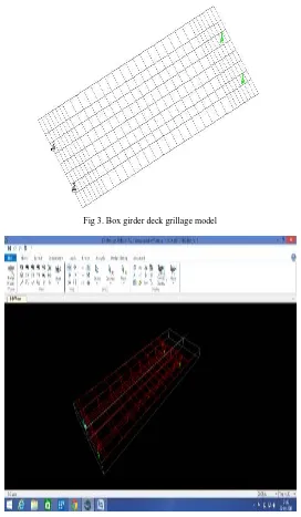
The box girder deck is analysed using manual calculations, grillage method and finite element method. The standard IRC loadings class A, class 70R tracked and wheeled are used. The grillage and finite element models are shown in Figures 3 and 4. The values of bending moment and shear force are compared for the three methods.
The manual calculations are done using Morice and Little method of distribution coefficients.The grillage method is done using STAADPro.V8i. It idealises the deck into a grid of beam elements with gridlines spaced according to positions of various components. Finite element analysis with CSiBridge is carried out using shell model of deck.Results are obtained and tabulated.
Department of CSE, MCA &CE, Mohandas College of Engineering and Technology, Thiruvananthapuram, Kerala, India
Fig 3. Box girder deck grillage model
Fig 4.Box girder finite element model
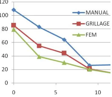
III. RESULTSANDDISCUSSION
A. COMPARISON OF THREE METHODS OF ANALYSIS
The comparison of three analysis methods for the box girder deck is shown in Table 1.
ISSN (Online) : 2319 - 8753
ISSN (Print) : 2347 - 6710
International Journal of Innovative Research in Science, Engineering and Technology
An ISO 3297: 2007 Certified Organization Volume 5, Special Issue 14, December 2016
3rd National Conference on Recent Trends in ComputerScienceand Engineeringand Sustainability in Civil
Engineering (TECHSYNOD’16)
19th, 20th and 21st December 2016
Organized by
Department of CSE, MCA &CE, Mohandas College of Engineering and Technology, Thiruvananthapuram, Kerala, India TABLE 1. COMPARISON OF THREE ANALYSES
Fig. 5Bending Moment Diagram for ClassA 2 Lane
Department of CSE, MCA &CE, Mohandas College of Engineering and Technology, Thiruvananthapuram, Kerala, India
Fig. 6 Shear force Diagram for ClassA 2 Lane
Fig. 7 Bending Moment Diagram for Class 70R Wheeled
ISSN (Online) : 2319 - 8753
ISSN (Print) : 2347 - 6710
International Journal of Innovative Research in Science, Engineering and Technology
An ISO 3297: 2007 Certified Organization Volume 5, Special Issue 14, December 2016
3rd National Conference on Recent Trends in ComputerScienceand Engineeringand Sustainability in Civil
Engineering (TECHSYNOD’16)
19th, 20th and 21st December 2016
Organized by
Department of CSE, MCA &CE, Mohandas College of Engineering and Technology, Thiruvananthapuram, Kerala, India
Fig.10 Shear force Diagram for Class 70R Tracked
IV. CONCLUSIONS
Finite element packages are powerful tools to analyse structures but care should be taken to ensure no errors are introduced anywhere in the process.
Results of finite element analysis have been found to be compatible with the values obtained from conventional and grillage methods.
The Finite element models yield the lowest value for bending moment and shear force than the other two methods. Hence it is more economical.
The grillage method is easy to use and comprehend because of its simplicity and ease of constructing a grillage model but is less accurate.
REFERENCES
[1] A. Morris, “A Practical guide to reliable finite element modeling “,John Wiley and sons Ltd ,2008 [2] J. Blaauwendraad, “Plates and FEM: Surprises and Pitfalls”, Springer Dordrecht Heidelberg, London, 2010 [3] Victor, J., “Essentials of Bridge Engineering”,Oxford and IBH Publishing company, New Delhi, Sixth Edition, 2012
[4] Jaegar, L. G and Bakht , B., “The grillage analogy in bridge analysis”, CanadianJournal of Civil Engineering, 1982, 9(2): 224-235, 10.1139/l82-025
[5] Amit Saxena,A., Savita Maru, S., “Comparative Study of the Analysis and Design of T-Beam Girder and Box Girder Superstructure”, International Journal of Research in Engineering & Advanced Technology, 1(2), 2013, pp 2320 - 8791
[6] Supriya Madda , Kalyanshetti M.G., “Dynamic analysis of T-Beam bridge superstructure“
[7] N.Munidruruppa and Dhruvaraja Iyengar, “Dynamic analysis of continuos span highway bridge ”, Iset Journal Of Earthquake Technology, 36(1)1999,pp.73-84
[8] E.Onate, “Structural analysis with the finite element method”, CIMNE,Vol.1,First edition,2009