ISSN (Online) : 2319 - 8753
ISSN (Print) : 2347 - 6710
I
nternationalJ
ournal ofI
nnovativeR
esearch inS
cience,E
ngineering andT
echnologyAn ISO 3297: 2007 Certified Organization Volume 4, Special Issue 3, March 2015
First National Conference on Emerging Trends in Automotive Technology (ETAT-2015)
Organized by
SAE INDIA Velammal Collegiate Club, Velammal Engineering College, Chennai, India on 20th March 2015
Comparative Study of Air Flow Analysis of A
Car Louvre
S.A. Wilfred Rajkumar
1, V.Vijayaraghunathan
2, S.Karthikeyan
3, I.Sharon Marishka
4Dr. MGR. Educational and Research Institute, University Adayalampattu, Chennai, Tamilnadu, India1,2,3 Velammal Engineering College, Chennai, Tamilnadu, India4
Abstract: Louvre is a shield protecting the radiator and engine compartment from any damage ,but at the same time
allowing maximum air to flow from outside to inside the engine. Existing profiles, though dissipates the heat effectively, are not much successful in arduous terrains like deserts and semi-deserts during extreme temperature conditions. The ideal profiling of a radiator cover should allow maximum airflow from outside to inside. This study deals with the comparison of different radiator Louvre profile using CFD analysis.
KEY WORDS: Louvre, CFD
I. INTRODUCTION
Louvre is used in any vehicle as radiator cover as they are protecting the radiator and engine compartment of any vehicle from damage. They should allow maximum air flow from outside to inside the radiator and the engine assembly. Protecting key engine components is crucial since a disabled vehicle cannot evade be driven to safety. A low cost sun screen device for use on motor vehicles is disclosed comprising a perforated polymer laminate sheet which is affixed to the interior surface of the vehicle rear window. The outermost surface of the laminate sheet includes artwork and other indicia formed thereon which when viewed by an observer through the rear window of the vehicle, simulates the appearance of a three-dimensional mechanical window louver structure. The perforated laminate sheet provides an aesthetically pleasing, effective sunshield which reduces the temperature of the interior compartment of the vehicle by as much as forty percent while insuring that occupant visibility is not adversely affected.
DIFFERENT TYPES OF SHAPES OF LOUVER GRILLE FOR RADIATOR COVER
The Louvre can be of any profile as shown in figure1. In the preferred embodiment, the grille is made of 4 mm thick steel bars place 8 mm apart to provide added protection to aluminium. Here in our study we shall slightly modify the profile and material of Louvre and the air flow through them can be studied in detail through CFD analysis.
Figure1. S –Shaped louver grille ,Semi- c shaped louver grille
SAE INDIA Velammal Collegiate Club, Velammal Engineering College, Chennai, India on 20 March 2015
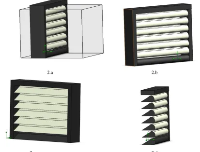
2.a 2.b
. 2.c 2.d
Figure 2. profile 1 a) full model with domain b) Back side view c) Front side view d) Cut section view of model
3.a 3.b 3.c
ISSN (Online) : 2319 - 8753
ISSN (Print) : 2347 - 6710
I
nternationalJ
ournal ofI
nnovativeR
esearch inS
cience,E
ngineering andT
echnologyAn ISO 3297: 2007 Certified Organization Volume 4, Special Issue 3, March 2015
First National Conference on Emerging Trends in Automotive Technology (ETAT-2015)
Organized by
SAE INDIA Velammal Collegiate Club, Velammal Engineering College, Chennai, India on 20th March 2015
II. CFD ANALYSIS
Computational fluid dynamics is a domain of finite element analysis in which the dynamics analysis of fluids can be studied. This study is one of the most common turbulence models. It is a two equation model that means it includes two extra transport equations to represent the turbulent properties of the flow. This allows a five equation model to account for history effects like convection and diffusion of turbulent energy.
The objective of CFD is to find out pressure and velocity distribution. The boundary conditions are specified below:
At Inlet we consider mass flow rate and at the outlet pressure is considered
The analysis is done for three specific conditions. By considering the vehicle to be a car at an average speed of 50 km/h.(i.e 40 km/h, 50 km/h) with the engine temperature assumed to be 80°C,90°C.The density of the air at the specified temperature are 0.9996 Kg/m3 and 0.9721 Kg/m3 respectively.
Inlet is been provided with fully developed flow condition to get possible accurate results. The Louvre walls have been provided with roughness. The model is designed using solid works and simulations are carried out in Flow Simulation 2013 SP3.0. Build: 2339.
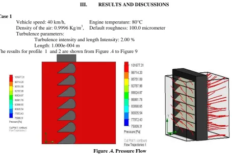
III. RESULTS AND DISCUSSIONS
Case 1
Vehicle speed: 40 km/h, Engine temperature: 80°C
Density of the air: 0.9996 Kg/m3, Default roughness: 100.0 micrometer Turbulence parameters:
Turbulence intensity and length Intensity: 2.00 % Length: 1.000e-004 m
The results for profile 1 and 2 are shown from Figure .4 to Figure 9
SAE INDIA Velammal Collegiate Club, Velammal Engineering College, Chennai, India on 20 March 2015
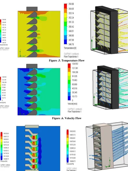
Figure .5. Temperature Flow
Figure .6. Velocity Flow
ISSN (Online) : 2319 - 8753
ISSN (Print) : 2347 - 6710
I
nternationalJ
ournal ofI
nnovativeR
esearch inS
cience,E
ngineering andT
echnologyAn ISO 3297: 2007 Certified Organization Volume 4, Special Issue 3, March 2015
First National Conference on Emerging Trends in Automotive Technology (ETAT-2015)
Organized by
SAE INDIA Velammal Collegiate Club, Velammal Engineering College, Chennai, India on 20th March 2015
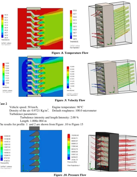
Figure .8. Temperature Flow
Figure .9. Velocity Flow Case 2
Vehicle speed: 50 km/h, Engine temperature: 90°C
Density of the air: 0.9721 Kg/m3, Default roughness: 100.0 micrometer Turbulence parameters:
Turbulence intensity and length Intensity: 2.00 % Length: 1.000e-004 m
The results for profile 1 and 2 are shown from Figure .10 to Figure 15
SAE INDIA Velammal Collegiate Club, Velammal Engineering College, Chennai, India on 20 March 2015
Figure .11. Temperature Flow
Figure .12. Velocity Flow
ISSN (Online) : 2319 - 8753
ISSN (Print) : 2347 - 6710
I
nternationalJ
ournal ofI
nnovativeR
esearch inS
cience,E
ngineering andT
echnologyAn ISO 3297: 2007 Certified Organization Volume 4, Special Issue 3, March 2015
First National Conference on Emerging Trends in Automotive Technology (ETAT-2015)
Organized by
SAE INDIA Velammal Collegiate Club, Velammal Engineering College, Chennai, India on 20th March 2015
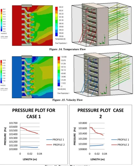
Figure .14. Temperature Flow
Figure .15. Velocity Flow
Figure .16. Pressure Plot comparision
101000 101100 101200 101300 101400 101500 101600 101700
0 0.02 0.04
P RE SS U RE (Pa) LENGTH (m)
PRESSURE PLOT FOR
CASE 1
PROFILE 1 PROFILE 2 100800 101000 101200 101400 101600 1018000 0.02 0.04
PRE SS URE ( Pa) LENGTH (m)
PRESSURE PLOT CASE
2
PROFILE 1
SAE INDIA Velammal Collegiate Club, Velammal Engineering College, Chennai, India on 20 March 2015
From figure 16 it is understand that profile 2 is better than profile 1 since there is a good variation in pressure drop in profile 2. The pressure is maintained almost constant in case 1 than case 2.
Figure .17. Temperature Plot comparision
From figure 17 it is understand that profile 2 is better than profile 1 since thereis good variation in temperatue in profile 2 . The curves in both the cases follows the same pattern.
Figure .18. Velocity Plot comparision
From figure 18 it ias infer that te cuve follows a similar pattern in both the cases. In profile 2 of both cases there is a sudden drop in velocity ,the velocity falls to zero .
IV. CONCLUSION
Radiator covers plays a vital role in ensuring the maximum engine performance by transferring heat
352.9985 352.999 352.9995 353
0 0.02 0.04
TE M PE R A TU R E (K ) LENGTH (m)
TEMPERATURE PLOT
CASE 1
PROFILE 1 PROFILE 2 362.99 362.992 362.994 362.996 362.998 363 363.002 363.0040 0.02 0.04
TE M PE R A TU R E (K ) LENGTH (m)
TEMPERATURE PLOT
CASE 2
PROFILE 1 PROFILE 2 0 10 20 30 40 500 0.01 0.02
VE
LOCI
TY
LENGTH (m)
VELOCITY PLOT CASE 1
PROFILE 1 PROFILE 2 0 10 20 30 40 50 60
0 0.02 0.04
VE
LOCI
TY
LENGTH (m)
VELOCITY PLOT CASE 2
PROFILE 1
ISSN (Online) : 2319 - 8753
ISSN (Print) : 2347 - 6710
I
nternationalJ
ournal ofI
nnovativeR
esearch inS
cience,E
ngineering andT
echnologyAn ISO 3297: 2007 Certified Organization Volume 4, Special Issue 3, March 2015
First National Conference on Emerging Trends in Automotive Technology (ETAT-2015)
Organized by
SAE INDIA Velammal Collegiate Club, Velammal Engineering College, Chennai, India on 20th March 2015
terrains like deserts and semi deserts. Considering the above said tasks, an optimized design of louver has been conceptually designed out of a structurally superior multilayered composite material and latter analysed under CFD.Various parameters like gauge pressure, volume flow rate and mass flow rate were analysed for the new designs and the results showed that the inlet and outlet air flow were equal with no losses and the profile 2 performance is better than that of profile 1.
REFERENCES
1. A.Achaichia,T.A.Cowell”Heat transfer and pressure drop characteristics of flat tube and Louvered plate fin surface” P no 147-157, in Experimental and Thermal Fluid Sciences , Elsevier science publishing company,1988
2. Mazlina, M.T., "Analysis on the Mechanical Performance of Epoxy Resin Reinforced by Natural Fibers" Kolej Universiti Teknologi Tun Hussein Onn.Tesis Sarjana Muda (2003).
3. Mohd Hafiz Mohd Noh, Ahmad Hussein Abdul Hamid, Helmi Rashid,Muhammad Faisal Iskandar”Numerical Investigation of Airfoil Louvers on the Air Duct Intake”, Advances in Mathematical and Computational Methods, ISSN 2160-0635,Volume 2, Number 1, March, 2012 4. Vashahi Foad, Myungjae Lee, Jintaek Kim, Byung Joon Baek, “A Simplified Numerical Analysis for the Performance Evaluation of
Intercooler”, Advanced Science and Technology Letters,Vol.41 (Mechanical Engineering 2013), pp.34-38.
5. Toshikazu Nakanishi,Tamotsu Nakamura,Youichirou Watanabe,Katsumasa Handou and Takahiro Kiwata, “Investigation of Air Flow passing through Louvers” 2007 ② VOL. 53 NO.160
6. Toshikazu Nakanishi, “Analysis of Flow Inside Engine Room - Report 2,” KOMATSU TECHNICAL REPORT Vol. 45, No. 2, pp.33 - 45 (1999).
7. TSI, Inc., Model 9230 COLORLINK Plus Multicolor Receiver, Instruction Manual, TSI Incorporated, St. Paul, MN, USA, 1999. 8. TSI, Inc., Model 0833 5-Beam Fiberoptic Probe, Instruction Manual, TSI Incorporated, St. Paul, MN, USA, 2001.
9. Atsushi Itoh, Toshikazu Nakanishi, et al., “High-speed Computational Fluid Dynamics (CFD) by Parallel Computer,” KOMATSU TECHNICAL REPORT Vol. 51, No. 156, pp.8 - 14 (2005).