Copyright to IJIRCCE DOI: 10.15680/IJIRCCE.2015. 0308141 7377
State Based Routing Protocol for Performance
enhancement under Wireless Sensor Network
Sulochana Madhukar Gore, Dr. Sulochana B. Sonkamble
PG Student, Dept. of Computer Engineering, RSSOER JSPM NTC, SPPU Pune University, India Professor and PG Guide, Dept. of Computer Engineering, RSSOER JSPM NTC, SPPU Pune University, India
ABSTRACT: Wireless Sensor Network (WSN) is highly insisted in the field of environmental calamity detection. To detect and prevent the affected area, requires an analysis of historical data and predict the critical zone. The protocol designed and implemented in this paper is an on demand multi hop and multiple destination protocol. This protocol establishes connection between critical event detected node and predicted critical nodes. In this approach, all sensor nodes are in passive mode until and unless any critical event happens. When critical event is detected this protocol transits the passive state to either active, critical and recovered states, as per the need in view to save energy. Number of packet relay in each state is different and hence the protocol named PACR (Passive, Active, Critical, Recovered). The WSN is also responsible for alerting the prevention system in the predicted critical zone by activating the preventing agencies attached with the sensor nodes. In this paper, the implementation perspective of the protocol is detailed and performance analysis is done with respect to AODV (Ad-Hoc On demand Distance Vector Protocol). Here, as the states of the nodes are changing dynamically is a state based implementation of wireless communication protocol consuming less energy.
KEYWORDS: Routing Protocol, State based information forwarder, Energy Efficient protocol, Wireless Sensor Network communication Protocol, Critical event management.
I. INTRODUCTION
Natural disaster is a natural event that inculcates major loss of lives and assets. The prediction algorithm proposed in this paper and implemented over the sensor node under WSN (Wireless Sensor Network) is an attempt to reduce the losses considerably. The area where the natural disaster is the frequent event over the years, like wildfire, we can deploy the sensor network and can predict the most probable affecting area and accordingly take a step of prevention in advance. The motivation behind the paper [1] is to reduce the losses, by taking an preventing step against the calamity by predicting the “might be affecting” area. The sensor nodes are turning their states according to the need of the application and the packets are routing through a special protocol designed and implemented in this paper called PACR routing protocol. PACR is the state based on demand multi hop protocol specially designed for the region where the natural disaster is a frequent problem like wildfire. By analysing the history data this protocol predicts the most probable affecting area and give signals to preventing agencies in advance in order to resist the future losses.
II. RELATED WORK
Copyright to IJIRCCE DOI: 10.15680/IJIRCCE.2015. 0308141 7378
repairing link breakages does not require global periodic routing advertisements as it requires in DSDV. DSR needs support from MAC layer to identify link breakages. As route is a part of packet itself, loopback is not formed and hence immediately removed. DSDV uses periodic route advertisement that unnecessarily uses network bandwidth. So this type of protocols is not suitable for large networks. On- demand protocols like AODV and DSR broadcast information only when needed. The reactive protocol hence more suitable for larger and static network.
PACR protocol is state based protocol and is a type of hybrid protocol. As sensor nodes are equipped with limited source of energy, the energy consumption is always a constraint. PACR protocol makes sensor nodes to change their states as per the need, energy utilization is optimum. PACR uses routing tables for maintaining the route information and gives better performance for static networks.
III.PROPOSED ALGORITHM
Proposed System has two modules, first is application level sensing module and second is network level routing protocol module.
A. Sensor Model
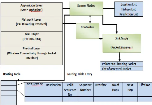
Multiple storage sensor nodes are connected with server and are grouped into the cluster. Each node maintains:
History list: History list is the list maintaining the history of detected fire temperature as data and node's remaining energy. All nodes store data its history table for a period.
Prediction list: Prediction list is critical data sensed node list.
Location list: It stores node's id and x and y location information.
Initially all sensor nodes in the cluster are in „sleep‟ or „passive‟ state, to save the batteries of the sensor node. When a critical event is detected, passive node sends a 'wake up ' call to its neibour nodes. All nodes those receiving critical event signal transit to „active‟ state. All active nodes now start searching critical data in its database. All nodes store critical data in its history table for a period. The active nodes which detected critical event are in the „critical‟ state. All critical state nodes send critical-information message to controller. If all nodes in range found critical data check will send node id to controller and the node is declared as critical. While node in critical state are showing prevention requisite zone. All other nodes stop transferring of packets to that node upto when it reaches to recovery state. If critical node data changed to normal state change node state to recovered. Else after a period of time declare as died-node. The architecture of the proposed system is given in figure 1.
Copyright to IJIRCCE DOI: 10.15680/IJIRCCE.2015. 0308141 7379
B. Controller Module:
Controller is act as a care service person to search for the active route and predict the critical zone. Controller maintains the threshold value to detect the critical event. If number of packets received from a node exceeds the threshold value that means a critical event has detected and it sets flag to 1 and broadcast the flag.
PACR State based Routing Protocol:
PACR is state based on- demand, multihop and multiple destinations routing protocol. It maintains the routing table for path discovery process and a request queue to buffer the packets for which route is currently not available.
Routing Table: Each Routing table has number of routing table entries, where each entry has following fields: 1. Pointer to net device.
2. Destination Address. 3. Validity of Sequence. 4. Sequence Number. 5. Interface Address. 6. Number of Hops. 7. Next Hop Address. 8. Lifetime
Request Queue: A "drop-front" queue used by the routing layer to buffer packets to which it does not have a route. Maximum time packets can be queued (in seconds) in the buffer is set to MaxQueueLen. The buffer has the maximum size MaxQueueLen. When controller issues an route request message, route discovery has been attempted for
RreqRetries times with the maximum TTL (Time to live). If no route reply received, then all data packets destined for the corresponding destination should be dropped from the buffer and a destination unreachable message should be delivered to the application.
IV.MATHEMATICAL MODELING
The system has i sensor nodes { n1, n2, n3, ...., ni | 1< i } mounted over 2 dimensional area with j clusters {k1,k2, ....kj
| j< i/α }where α is the node density parameter of a cluster. Each cluster has a cluster head collecting the cluster sensory data called sink. Few nodes say M are working as care service nodes called controllers. Each sensing node maintains three lists:
1. History list LH
2. Prediction list LP
3. Location list LL
Initially sensing nodes are set with the 'passive' state and threshold value Sth. If any node sensed the input
environmental parameter (temperature) beyond Sth, it sends a wakeup call to all its reachable nodes. All nodes those
received wakeup call are transit to state 'active'. Those nodes who have received the wakeup call and has a critical history, then that node is declared itself a 'critical' node and blocks itself to receive any more signals for the period of time. Critical node retaining its state until and unless it reaches to the normal state, at that time is transit to 'recovered' state otherwise is declared as died and removed from the sensor list as it is thought of died.\\
States = {Passive P, Active A, Critical C, Recovered R}
Input: Environmental Temperature tmp
Output: Predicted sequence of critical nodes C= {n1, n2,,... nn}
Passive state nodes are sending no packets until and unless input temperature exceeds the predefined threshold value Sth. When temperature exceeds threshold then it turns to 'active' state and sends p packets per second.
Copyright to IJIRCCE DOI: 10.15680/IJIRCCE.2015. 0308141 7380
Initially,
S (n) = P for all n=1, 2, ..., i
S (n, t) = {X | X ε P{s}} for n=1, 2,...., i and t=1, 2 ...T otherwise
(1) In the history table all states of the node is maintained for a period of time T. Each time period is divided into the interval of time t called time epoch. Let say H (t) is the function defines the history of all sensor nodes n=1,2,...i and can be defined as,
H (n) = {Sequence of states O1, O2, O3 ...OT} | ∀ O ε PS}
where Oi is the observed state of the nth node at time t=1, 2 ...T. (2)
When a nodes senses critical data it sends a notification to the controller. Controller sets a flag and broadcast this flag to all reachable nodes and searches for the active route. All nodes start searching critical data check in their respective history table. If a critical history is found, that node is set to critical, All critical nodes establishes a route to source and give notification to it. The list of critical nodes can be given as,
C = {C1, C2, C3 .... Cm| 0 < m < i } (3)
Critical nodes blocked themselves to receive more packets until and unless it reaches to recovered state. This is the predicted list of the critical nodes indicting the critical zone.
V. EXPERIMENTAL SETUP
A. Network Formation
Network Simulation has 23 nodes in the network. Two nodes are set as controller and rests of nodes are forming three clusters. Each cluster has a cluster head for network. The Simulation parameters defined and used are indicated in the table 1.
TABLE 1
PACR PROTOCOL NETWORK DESIGN PARAMETERS
Parameter Values
Simulator NS- 3 Protocol PACR Simulation Time 5 sec Transmission range 30 m Traffic type UDP Packet Size 12 bytes Total no of nodes 23 Data rate 100 Kbps
The PACR protocol has four types of communication messages:
RREQ: Route Request,
RREP: Route Reply,
RERR: Route Error,
RREP_ACK: Route to Request Acknowledgment.
Copyright to IJIRCCE DOI: 10.15680/IJIRCCE.2015. 0308141 7381
TABLE2
PACR COMMUNICATION PARAMETERS
VI.PROPOSED SYSTEM IMPLEMENTATION
A. Design and Workflow
When a node senses a critical event, it sends a route request RREQ to controller for searching the predicate nodes. Sender node is treated as destination and all neibours who has critical history are source, as we walk through the reverse path. A node should not originate more than RreqRateLimit messages per second. Then create a RREQ header and send RREQ as subnet directed broadcast from each interface used by PACR. At the receiver side node checks to determine whether it has received a RREQ with the same Originator IP Address and RREQ ID. If such a RREQ has been received, the node silently discards the newly received RREQ, as it is a duplicate RREQ. Otherwise increment
Parameter Notataion Description Value
RreqRetries Rxr Maximum number of retransmissions of RREQ to discover a route 2
RreqRateLimit Rqr Maximum number of RREQ per second 10
RerrRateLimit Rer Maximum number of RERR per second 10
NodeTraversalTime Ndt Conservative estimate of the average one hop traversal time for packets and it include queuing delays, interrupt processing times and transfer times.
40 ms
NextHopWait Tack Period of waiting for the neighbour's route reply acknowledgment Ndt +10 ms
ActiveRouteTimeout Rat Period of time during which the route is considered to be valid 3 sec
MyRouteTimeout Tor Value of lifetime field in RREP generating by this node 2* max
(Rt, Tpd)
BlackListTimeou TB Time for which the node is put into the blacklist Rxr*Nt t
DeletePeriod TD DeletePeriod is intended to provide an upper bound on the time for which an upstream node A can have a neighbor B as an active next hop for destination D, while B has invalidated the route to D
5*max(HelloIn terval, Ra t )
NetDiameter Hm Net diameter measures the maximum possible number of hops between two nodes in the network
35 m
NetTraversalTime Nt t Estimate of the average net traversal tim 2*Ndt * Hm
PathDiscoveryTime Tpd Estimate of maximum time needed to find route in network 2*Nt t
MaxQueueLen Mql Maximum number of packets that we allow a routing protocol to buffer 64
MaxQueueTime Mqt Maximum time packets can be queued (in seconds) (M q t)
30 sec
AllowedHelloLoss Lnh Number of hello messages which may be loss for valid link 2
GratuitousReply Rpg Indicates whether a gratuitous RREP should be unicast to the node originated route discovery
true
DestinationOnly - Indicates only the destination may respond to this RREQ false
EnableHello - Indicates whether a hello messages enable false
EnableBroadcast - Indicates whether a broadcast data packets forwarding enable. true
Copyright to IJIRCCE DOI: 10.15680/IJIRCCE.2015. 0308141 7382
RREQ hop count. If a valid route not found, then packets are buffered and it create loopback route. It is asserted that the only one interface up for now is loopback. The loopback route is entered into routing table entry.
The snapshots of the animation of PACR protocol is shown in figure 2 and 3. Figure 2 shows the blue colour passive nodes and green colour active nodes with two black colour controller nodes. In figure 3 predicted critical nodes are denoted by red colour. The animation tool NetAnim is used to create an interface to the animation with simulation of PACR.
Fig 2: Proposed system animation showing passive and active state Fig 3: Proposed system animation showing state active and critical state
When the current node is destination then Destination node must increment its own sequence number by one if the sequence number in the RREQ packet is equal to that incremented value. Otherwise, the destination does not change its sequence number before generating the RREP message. A node ignores all RREQs received from any node in its blacklist
When the reverse route is created or updated, the following actions on the route are also carried out:
1. The Originator Sequence Number from the RREQ is compared to the corresponding destination sequence number in the route table entry and copied if greater than the existing value there.
2. The valid sequence number field is set to true.
3. The next hop in the routing table becomes the node from which the RREQ was received. 4. The hop count is copied from the Hop Count in the RREQ message;
5. The Lifetime is set to be the maximum of (Existing Lifetime, Minimal Lifetime) ,
where MinimalLifetime = ( current time + 2 * Net Traversal Time - 2* HopCount * Node Traversal Time)
A node generates a RREP if either (i) it is itself the destination (ii) or it has an active route to the destination, the destination sequence number in the node's existing route table entry for the destination is valid and greater than or equal to the Destination Sequence Number of the RREQ, and the "destination only" flag is not set.
RouteRequestTimerExpire: If a route discovery has been attempted RreqRetries times at the maximum TTL without receiving any RREP, all data packets destined for the corresponding destination should be dropped from the buffer and a destination unreachable message should be delivered to the application
SendRerrWhenNoRouteToForward: A node should not originate more than RERR_RATELIMIT RERR messages per second. Just make sure that the RerrRateLimit timer is running and will expire discard the packet and return. If there is only one precursor, RERR should be unicast toward that precursor should only transmit RERR on those interfaces which have precursor nodes for the broken route.
VII. ALGORITHM
Copyright to IJIRCCE DOI: 10.15680/IJIRCCE.2015. 0308141 7383
void Start ();
3. Process hello message
void ProcessHello (RrepHeader const & rrepHeader, Ipv4Address receiverIfaceAddr); 4. If route exists and valid, forward packet.
bool Forwarding (Ptr <const Packet> p, const Ipv4Header & header, UnicastForwardCallback ucb, ErrorCallback ecb); 5. If route does not exist and de_ered then queue packet and send route request.
void DeferredRouteOutput (Ptr<const Packet> p, const Ipv4Header & header, UnicastForwardCallback ucb, ErrorCallback ecb);
Send RREQ
void SendRequest (Ipv4Address dst);
Route Discovery Process
6. Packet Duplication Check
Check wheather the packet is sent from own interface bool IsMyOwnAddress (Ipv4Address src);
7. Reduce Congestion
To reduce congestion in a network, repeated attempts by a source node at route discovery for a single destination MUST utilize a binary exponential backoff.
void ScheduleRreqRetry (Ipv4Address dst); 9. Lifetime Updation
For each hop, set lifetime field in routing table entry to the maximum of existing lifetime and lt, if entry exists .In parameter addr is the destination address and lt is the proposed time for lifetime field in routing table entry for destination with address addr. This returns true if route to destination address exist.
bool UpdateRouteLifeTime (Ipv4Address addr, Time lt); 10. Update Neighbor
Update neighbor records where parameter receiver is supposed to be current nodeinterface and sender is the IP address of nodes neighbor.
Void UpdateRouteToNeighbor(Ipv4Address sender, Ipv4Address receiver); 11. Find socket
Find socket with local interface address iface
(Ptr<Socket>FindSocketWithInterfaceAddress (Ipv4InterfaceAddress iface) const); 12. Send RREP
When source found then send RREP to destination.
void SendReply (RreqHeaderconst & rreqHeader, RoutingTableEntry const & toOrigin);
If RREP is by intermediate node then call SendReplyByIntermediateNode and the parameters toDst is routing table entry to destination, toOrigin is routing table
entry to originator and gratRep indicates whether a gratuitous RREP should be unicast to destination.
void SendReplyByIntermediateNode (RoutingTableEntry & toDst, RoutingTableEntry &toOrigin, bool gratRep); 13. Send RREP ACKNOWLEDGEMENT
void SendReplyAck (Ipv4Address neighbor); 14. Send Packet from queue on the identified route
Void SendPacketFromQueue(Ipv4Address dst, Ptr <Ipv4Route> route); Forward packet on the route:
void SendTo (Ptr<Socket> socket, Ptr<Packet> packet, Ipv4Address destination); 15. Loopback
If valid route not found, return loopback.Create loopback route for given header.
Ptr < Ipv4Route > LoopbackRoute(constIpv4Header & header , Ptr <NetDevice >oif )const;
Error Handling
Copyright to IJIRCCE DOI: 10.15680/IJIRCCE.2015. 0308141 7384
void SendRerrMessage (Ptr< Packet>packet, std:: vector <Ipv4Address> precursors);
3. Send RERR message when no route to forward input packet. Unicast if there is reverse route to originating node, broadcast otherwise. Parameter dst is the destination node IP address and dstSeqNo is destination node sequence number, origin is the originating node IP address.
void SendRerrWhenNoRouteToForward (Ipv4Address dst, uint32 t dstSe- qNo, Ipv4Address origin);
VIII. RESULTS
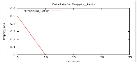
The simulation has conducted with different data rates from 5 to 25 Kbps and results are collected for following performance metrics:
1. Packet Delivery Ratio 2. Throughput.
3. Delay 4. Jitter
5. Packet Dropping Ratio
In paper [7], we have following results as shown in figure 4 and 5. It shows comparative performance of AODV and Extended AODV. In AODV Packet Delivery ratio is decreased as data rate increases but in PACR implementation it has reached to 100% for lower data rate as shown in table 3 and figure 6.
Fig 4: AODV results for data rate vs Packet Delivery ratio. Fig 5: AODV results for data rate vs Average Delay
The end to end delay of PACR implementation is also improved as compared it with AODV protocol. Fig 5 and figure 9 has result of AODV and PACR implementation for data rate vs delay. The PACR protocol performance parameters reading are as given in table 3. We received 100% packet delivery and a constant throughput. The packet delivery ratio is also 0 ensures data delivery and hence improves network performance.
The PACR is showing the better performance as compared to AODV for static networks.
TABLE 3.
PACR result for data rate vs packet delivery ratio, throughput, delay, jitter and Dropping ratio
Data Rate Packet Delivery Ratio Throughput Delay Jitter Dropping Ratio
5 99.4949 773 +3562393.0ns +4221561.0ns 0.505051
10 100 777 +614915.0ns +503082.0 ns 0
15 100 777 +5926715.0ns +5741501.0ns 0
20 100 777 +522402.0ns +322525.0ns 0
Copyright to IJIRCCE DOI: 10.15680/IJIRCCE.2015. 0308141 7385
The graphical results for all metrics are shown through the figures 6 to 10 as shown below:
Fig 6. PACR result, data rate vs Packet Delivery Ratio Fig 7. PACR result, data rate vs Throughput
Fig 8. PACR result, data rate vs Delay Fig 9 . PACR result, data rate vs Jitter
Fig 10 . PACR result, data rate vs dropping ratio
Figure 7 shows the throughput of experimental result for different data rates which is 777 and is constant for higher data rates. It is driven from graphs that PACR implementation ensures better performance than AODV for packet delivery ratio and end to end delay. PACR protocol gives maximum throughput and minimum dropping ratio.
IX.CONCLUSION
Copyright to IJIRCCE DOI: 10.15680/IJIRCCE.2015. 0308141 7386
some event has happened. In sensor network critical event detection, sensor nodes are reporters and responsible to sense environmental dimensions for any critical anomaly detection .The sink node is the actor node and responsible to take the appropriate action against the calamity. This model leads the automation and gives an intelligent system that prevents the more losses due to the natural disaster.
The PACR protocol implemented here is a on demand state based multi hop protocol. It maintains the routing table entries for route discovery of the neibour„s who are having critical history. As compared to AODV and DSR this PACR model gives more throughput and minimum delay. Critical nodes blocks themselves to receive packets, this feature improves the network performance by reducing the network congestion. As in advance all neibour nodes who are having critical history are going to active and their attached preventing system like actuator are become active in advance to resist the spread of the critical event. Hence this attempt reduces the losses because of critical event considerably, by predicting and activating the preventing agencies well in advance.
REFERENCES
[1] Sulochana Gore, Dr.SulochanaSonkambale “Critical Event Management In Wireless Sensor Network” International Journal of Science and Research. Volume 4 Issue 1, January 2015.
[2] Mohamed M.E.A. Mahmoud and Xuemin (Sherman) Shen, Fellow, IEEE “A Cloud-Based Scheme for Protecting Source-Location Privacy against Hotspot-Locating Attack in Wireless Sensor Networks” IEEE transactions on parallel and distributed systems, vol. 23, no. 10,October 2012.
[3] Ping Jiang, Jonathan Winkley, Can Zhao, Robert Munnoch, Geyong Min, and Laurence T. Yang, Member, IEEE “An Intelligent Information Forwarder for Healthcare Big Data Systems With Distributed Wearable Sensors” “IEEE systems journal 1932-8184 © 2014 IEEE.
[4] Daisuke Takaishi , Hiroki Nishiyama , Nei Kato , and Ryu Miura School of Information Sciences, Tohoku University, Sendai, Japan “Towards Energy Efficient Big Data Gathering in Densely Distributed Sensor Networks” DOI10.1109/TETC.2014.2318177, IEEE Transactions on Emerging Topics in Computing.
[5] Chunsheng Zhu, Student Member, IEEE, Hai Wang, Student Member, IEEE, Xiulong Liu, Lei Shu, Member, IEEE,Laurence T. Yang, Member, IEEE, and Victor C. M. Leung, Fellow, IEEE “A Novel Sensory Data Processing Framework to Integrate Sensor Networks With Mobile Cloud”IEEE systems journal 1932-8184 © 2014 IEEE
[6] “Performance analysis of AODV, DSR and TORA” Routing Protocols”IACSIT International Journal of Engineering and Technology, Vol.2, No.2, April 2010
[7] Patil Varsha, “Efficient AODV Routing Protocol for MANET with enhanced packet delivery ratio and minimized end to end delay”International Journal of Scientific and Research Publications, Volume 2, Issue 8, August 2012
[8] P. Indyk and R. Motwani, “Approximate nearest neighbors: Towards removing the curse of dimensionality,” in Proc. 30th Annu. ACM Symp.Theory Comput., Dallas, TX, USA, 1998, pp. 604–613.
[9] M. Slaney and M. Casey, “Locality-sensitive hashing for finding nearest neighbors,” IEEE Signal Process. Mag., vol. 25, no. 2, pp. 128– 131,Mar. 2008. Operations Research: Theory and Applications 5th Edition by Sharma J K
[10] K.S. Trivedi “Probability and Statistics with. Reliability”
[11] B. Aditya Prakash , Hanghang Tong , Nicholas Valler , Michalis Faloutsos, and Christos Faloutsos “Virus Propagation on Time-Varying Networks: Theory and Immunization Algorithms”
[12] An Integrated System for Regional Environmental Monitoring and Management Based on Internet of Things by Shifeng Fang, Li Da Xu, Senior Member, IEEE, Yunqiang Zhu, Jiaerheng Ahati, Huan Pei, Jianwu Yan, and Zhihui Liu IEEE transactions on industrial informatics, vol. 10, no. 2, May 2014
[13] Fang Zhaho, Leonidas Guibas, “Wireless Sensor Networks:An information Processing Approach”, Elsevier ISBN: 978-81-8147-642-5
[14] Kazim Sohraby, Daniel Minoli, Taieb Znati, “Wireless Sensor Networks: Technology,
BIOGRAPHY
Sulochana M. Gore has received her B.E. degree in Computer Science and Engineering from Aurangabad University, Maharashtra State, India, in 2006. She is currently pursuing her M.E. degree in Computer Engineering from Rajarshi Shahu School of Engineering and Research , Narhe, Pune, Pune University, Maharashtra State, India. During the period 2007 to 2013she has worked as a lecturer in Aurangabad and Pune University in the department of Computer Engineering.