2019 International Conference on Computation and Information Science (ICCIS 2019) ISBN: 978-1-60595-644-2
An Improved Wireless Sensor Network
Protocol Based on LPL Protocol
Zhang Dong, Yufeng Chen, Yilin Luo, Zhengtao Xiang
and Yabo Dong
ABSTRACT
This paper proposes a Lora-based LPL improved protocol, which use the method of divides the wake-up packet into multiple small wake-up units to reduce the energy loss of the receiving nodes in the wake-up process. Through theoretical derivation and experimental verification, the relationship between the number of wake-up units and the energy consumption of the destination nodes, as well as the relationship between the number of wake-up units and the destination nodes' wake-up success rate is obtained, which verifies the feasibility of the LPL improved protocol.
1. INTRODUCTION
Wireless sensor network (WSN) is a technology developed very rapidly in recent years. It uses sensor and wireless communication for information acquisition and processing. The nodes in WSN generally provided energy with dry batteries, button batteries etc. which energy is often difficult to replenish. Therefore, energy saving becomes a primary consideration in the MAC protocol of WSN.
Low power listening (LPL) is a typical MAC protocol applied to wireless sensor networks. Its basic idea is that the sleep node periodically wakes up to detect the RF activity[1-3]. If detected, the node will keep active, otherwise return to sleep. In LPL, transmitting node must send expensive long messages to ensure that the receiving node can receive the payload. Since there is no wakeup-sleep scheduling used to coordinate the sending and receiving node, the transmitting node needs to send a preamble whose length is equal to the detection period to wake up the receiving node. Since neighbor nodes share the same wireless channel, data sent by the transmitting node can reach every node in the range of RF transmission. Though neighbor nodes
Zhang Dong, Hubei University of Automotive Technology, Shiyan, 442000, China
Co-corresponding author: Yufeng Chen, Hubei University of Automotive Technology, Shiyan, 442000, China
are not destination nodes, they will still spend energy to receive the data, which result in overhearing expense. Overhearing expense is one of the main causes of energy waste in WSN, and idle listening is one of the most important factors affecting energy efficiency. By transferring the burden of synchronization to the transmitting node and turning off the RF most of the time to decrease the RF duty cycle, LPL reduce the energy waste in idle listening effectively. However, LPL does not consider reducing overhearing expense, which is undoubtedly more significant in dense deployments due to the large number of non-destination nodes. In consequence, reducing overhearing expense will help improve energy efficiency further.
This paper proposes a Lora-based LPL improved protocol, which use the method of divides the wake-up packet into multiple small wake-up units to reduce the energy consumption of the receiving node. The payload length of these wake-up units is adjustable, and each payload of the wake-up unit contains a complete wake-up information, such as address of the destination node, the number of remaining wake-up units, wake-up signal, wake-up behavior and wake-up communication band etc.. Since the number of wake-up units will also affect the wake-up success rate of the nodes, the relationship between the number of wake-up units and the energy consumption of the destination nodes, as well as the relationship between the number of wake-up units and the destination nodes’ wake-up success rate is obtained through theoretical derivation and experimental verification. What’s more, this LPL improved protocol is applicable to the increasingly mainstream Lora technology in today's WSN.
2.RELATED WORKS
LPL uses a method of periodically detecting radio frequency and sending a long preamble to wake up the receiver before sending a packet. This idea was first introduced into the wireless sensor network by Hill and EL-Hoiydi independently.
In terms of improvements to LPL, WiseMac improves the LPL protocol by reducing the length of the preamble. The main idea is to use a long preamble in the first wake-up packet, and piggyback the next detection time of the receiver in the returned response packet, so that the sender can use a short preamble for the next transmission[4].Similarly, the SP also recommends piggybacking the channel detection scheduling information when transmitting a packet containing long preamble[5].
SCP-MAC proposes a crosstalk avoidance protocol based on MAC layer header. The receiver checks the destination address of the packet after receiving the MAC header. If the node is not the destination node, it will immediately stop receiving and turn off the radio[6].Since it may have been received a quite long preamble before Mac header, the energy saved by this method is very limited.
SLPL proposes to add destination address and preamble index information to the preamble to improve the energy efficiency of LPL, but it is only applicable to sensor nodes whose preamble content can be modified[7].For sensor nodes using Lora modulation technology, since it only supports to modify the length of preamble, it does not apply.
embedding scheduling information in the preamble is suitable for the increasingly mainstream Lora technology.
3.DESIGN OF LPL IMPROVED PROTOCOL
The Lora chip has eight working modes. When it is in the CAD mode, the device will detect the Lora preamble signal on the current channel. (After experiment, we find that the payload signal can also be detected in CAD mode.) When the device detects the preamble or payload signal, it will exit CAD mode, and if let the device enter receiving mode, it will start to receive the payload. After receiving finish, the device will enter other working states [8,9].
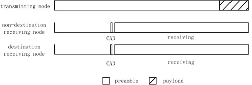
In traditional LPL, a long preamble is sent to wake up the receiver before sending each packet. The length of the preamble must be longer than the sleep period of the node. The working states of the sending and receiving nodes in a wake-up cycle are shown in Figure. 1. If the receiving node detects the transmission data signal, it remains in the receiving state until the payload is received completely. If no transmission data signal is detected, the radio frequency will be turned off and the node will enter the sleep mode until the next wake-up cycle.
transmitting node
non-destination receiving node
CAD destination
receiving node
CAD
preamble payload receiving
[image:3.612.170.428.350.437.2]receiving
Figure 1. Working states of the nodes in tradition LPL.
…
CAD
CAD
receiving
…
energy saving
preamble payload sending node
non-destination receiving node
destination receiving node
[image:4.612.171.420.86.185.2]energy saving receiving
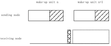
Figure 2. Working states of the nodes in LPL improved protocol.
The number of wake-up units, that is, the proportion of the transmission gap in a wake-up packet will affect the wake-up success rate and the energy consumption of destination nodes. As shown in Fig. 3, since the time of cad detection is shorter than transmission gap, if the receiving node makes CAD detection exactly during the transmission gap of the wake-up packet, the receiving node will not enter the receiving mode, which will result in a wake-up failure.
wake-up unit n wake-up unit n+1
receiving node
CAD mode Receiving mode sending node
Figure 3. Failure to enter receiving mode.
[image:4.612.209.396.372.450.2]wake-up unit n wake-up unit n+1
receiving node
[image:5.612.223.400.64.152.2]CAD mode Receiving mode sending node
Figure 4. Failure to receive a full payload.
If the receiving node make CAD detection exactly when the transmitting node sends payload, it will also cause a wakeup failure since a full payload cannot be received. To avoid this situation, the receiving timeout can be set to the time that is required to send 2 complete wake-up units, as shown in Fig. 5.
wake-up unit n wake-up unit n+1
receiving node
[image:5.612.220.400.318.405.2]CAD mode Receiving mode sending node
Figure 5. Receiving timeout.
With the increase of the number of wake-up units, the total time of transmission gap becomes longer. The proportion of the total time for transmitting data in a wake-up period will become smaller while the transmission rate is constant, which result in a lower wake-up success rate. At the same time, with the increase of the number of wake-up units, the node can quickly accept the information in the payload, so that the sleep time is increased, and the total energy consumption due to overhearing is reduced. Therefore, it is necessary to verify the relationship between the number of wake-up units with the node energy consumption and the node wake-up success rate.
4.THEORETICAL ANALYSIS
The model parameters and typical values on the Lora RF chip SX1276 are listed in TABLE I. The lower limit of preamble transmission time tpreamble is the time required
TABLE I. MODELPARAMETERSONLORAPLATFORM.
Parameter Value Parameter Description
SF 7 Rf parameters
BW 500KHz bandwidth
preamble
t 0.0036-0.9826s Preamble transmission time
aux
t 0.0097s Payload transmission time
gap
t 0.005s Transmission gap
cad
t 0.0015s CAD detected time
T 1s Wake-up period
cad
p 40mW RF detection power
receive
p 45mW RF transmission power
sleep
p 0.015mW RF sleep power
There are three working mode of the receiving node: the receiving mode, the CAD mode, and the sleep mode. The time and average power corresponding to the three modes are treceive, tcad, tsleep, Preceive, Pcad, Psleep respectively. Since both the preamble
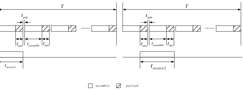
and payload can wake up the receiving node, if the wake-up source is preamble, the mathematical expectation of receiving time treceive1can be expressed as formula 1.
1 0.5 aux
receive preamble
t t t (1)
If the wake-up source is payload, the mathematical expectation of receiving time
treceive2 can be expressed as formula 2.
2 1.5aux
receive preamble gap
t t t t (2)
…… T 1 receive t aux t preamble payload gap t aux t …… T preamble t taux
[image:7.612.105.503.52.200.2]gap t aux t preamble t 2 receive t
Figure 6. Receiving time.
Therefore, according to the proportion of the preamble and the payload in the wake-up unit, the sleep time can be expressed as formula 3.
( (0.5 ) (1.5 )) / ( )
receive preamble preamble aux aux aux preamble gap preamble aux
t t t t t t t t t t (3)
Similarly, since sleep time is the time remaining except for CAD and transmission time in a wake-up period. The sleep time tsleep can be expressed as formula 4.
1
2
(
) / (
)
(
) / (
)
cad aux
aux cad aux
sleep preamble receive preamble
receive preamble
t
t
T
t
t
t
t
t
T
t
t
t
t
(4)
In the analysis, one wake-up period T is 1 second. The wake-up failure rate of receiving node can be expressed as the percentage of total transmission gap in a wake-up period T, that is, the wake-up failure rate can be expressed as formula 5.
' ntgap/T
(5)
In which n is the number of wake-up units. Therefore, the wake-up success rate of the node can be expressed as formula 6.
1
'
(6)
For convenience of calculation, assuming that the node receives the first wake-up unit, the average power consumption W during the wake-up period T can be expressed as the sum of the average power consumption of the nodes in each working mode, as shown in formula 7.
cad cad receive receive sleep sleep
Considering the wake-up success rate, there is no transmits consumption when the wake-up fails. Therefore, its average power consumption during the wake-up period T
can be expressed as formula 8.
(
)
(
(
)) '
cad cad receive receive sleep sleep
cad cad sleep cad
W
p
t
p
t
p
t
p
t
p
T
t
(8) [image:8.612.190.406.267.393.2]Substituting the parameters in Table 1 into calculation, the relationship between the number of wake-up units and the energy consumption of the destination nodes, as well as the relationship between the number of wake-up units and the destination nodes’ wake-up failure rate in unit time is shown in the Figure.7.
Figure 7. Wake-up failure rate and average power consumption under different number of wake-up unit.
5.EXPERIMENTAL VERIFICATION
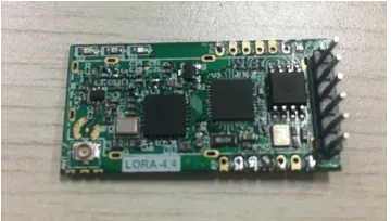
This paper implements the improved protocol of LPL on SX1276.Using the MCU of SIM3L144,and using the Lora module of ATZGB-Z02. The experiment environment is shown in Figure. 8.The parameter values used are as shown in Table 1.
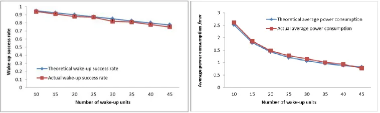
[image:8.612.215.395.549.651.2]Each wake-up unit has 19 bytes payload. Adjusting the number of wake-up units (the preamble length of the wake-up unit), and observing the wake-up success rate and average energy consumption of the destination node within 1 hour. The result is shown as Figure. 9.
Figure 9. Comparison of experimental and theoretical results.
It can be seen from the results in the figure that the experimental results are basically consistent with the theoretical derivation results. The wake-up failure rate when the number of wake-up units is 45 is 20% higher than that when the number of wake-up units is 10, while the average power consumption is 67% lower. The error rate of both wake-up success rate and power consumption is less than 10%. Therefore, the theoretical derivation is established.
6. CONCLUSIONS
The traditional LPL adopts a method of periodically detecting radio frequency and sending a long preamble to wake up the receiving node before sending each data packet, which will generate huge overhearing expense. This paper proposes a Lora-based LPL improved protocol, which use the method of divides the wake-up packet into multiple small wake-up units to reduce the energy loss of the receiving nodes in the wake-up process. Through theoretical derivation and experimental verification, the relationship between the number of wake-up units and the energy consumption of the destination nodes, as well as the relationship between the number of wake-up units and the destination nodes’ wake-up success rate is obtained, which verifies the feasibility of the LPL improved protocol.
ACKNOWLEDGEMENTS
REFERENCES
1. Lazarescu, Mihai T. 2013."Design of a WSN Platform for Long-Term Environmental Monitoring for IoT Applications," IEEE Journal on Emerging and Selected Topics in Circuits and Systems, 3(1):45-54.
2. Sohrabi K, Gao J, Ailawadhi V, et al. 2000. "Protocols for self-organization of a wireless sensor network," IEEE Personal Communications, 7(5):16-27.
3. Mao G, Fidan B, Anderson B D O. 2007. "Wireless sensor network localization techniques,"Computer Networks, 51(10):2529-2553.
4. Hurni P, Braun T, Anwander M. 2010."Evaluation of WiseMAC and extensions on wireless sensor nodes," Telecommunication Systems, 43(1-2):49.
5. Hu W, Chen Q, Corke P, et al.2010. "An Energy-efficient Rate Adaptive Media Access Protocol (RA-MAC) for Long-lived Sensor Networks," Sensors, 10(6):5548-5568.
6. Ullah N, Khan P, Kwak K S. 2011."A Very Low Power MAC (VLPM) Protocol for Wireless Body Area Networks,"Sensors, 11(12):3717-3737.
7. Lu G, Krishnamachari B, Raghavendra C S. 2004. "An Adaptive Energy-Efficient and Low-Latency MAC for Data Gathering in Wireless Sensor Networks," 18th International Parallel and Distributed Processing Symposium, Abstracts Proceedings.
8. Jurdak R. 2007. "Adaptive Low Power Listening for Wireless Sensor Networks," IEEE Transactions Mobile Computing, 6(8):988-1004.
9. Cano C, Bellalta B, Sfairopoulou A, et al. 2009. "A low power listening MAC with scheduled wake up after transmissions for WSNs," IEEE Communications Letters, 13(4):221-223.