Design and Implementation of PID Controller
for Single Capacity Tank
Vikas Karade1, Ambadas Shinde2, Sagar Sutar3
Asst. Professor, Department of Instrumentation Engineering, P.V.P.I.T. Budhgaon, Maharashtra, India1 Asst. Professor, Department of Electronics Engineering, P.V.P.I.T. Budhgaon, Maharashtra, India1 Asst. Professor, Department of Instrumentation Engineering, M.P.C.O.E. Velneshwar, Maharashtra, India1
ABSTRACT: The industrial application for controlling of single capacity tank is widely used in almost all process industries and most commonly used in chemical industries. Controlling of single capacity tank by using PID controller is presented in this paper. In this paper, Ziegler Nichols method is used for setting the parameters of PID controller. Simulation is done by using identification toolbox of MATLAB to check the performance of system. As the system is nonlinear, initially it becomes essential to linearise the process model and then PID controller is designed for the system. The best fit simulation results of actual process are 83.17, which are much encouraging.
KEYWORDS:PID controller, Tuning of PID, Water level control I. INTRODUCTION
Three Mode Controller (PID) is one of the most powerful but complex controller mode operations which combines proportional, Integral and derivative modes together. The PID Controller is invented in 1910 and the Ziegler-Nichols (Z-N) tuning method in 1942[1]. Now days PID is widely used in various industries. By using PID we get output within minimum error and overshoot. Liquid level control plays important role in large scale industries like chemical and petrochemical industries. Nonlinear system PID controller is more beneficial than PI controller. PID controller offers simplest solutions for the real world problems. In level control applications, PID controls the level of liquid according to given set point and it is able to accept new set point value at the run time. For developing the control system it is necessary to develop mathematical model of the process. This paper considers designing PID controller for single capacity tank system using MATLAB software.
The organization of paper is as follows: Section II describes all related work done earlier. The mathematical model of single tank level control is given in Section III. In section IV the designing of PID controller, its mathematical representation and PID controller parameters using ZN method are presented. Experimental results are described in section V. Section VI deals with the conclusion.
II. RELATEDWORK
In process industries, level control mechanism is extensively used. In process applications, it is required to pump the water into the tank and there are various methods used to tune the PID controller to find appropriate values of the parameters.
Our system objective is to design PID controller to maintain the level in tank. The model considered to develop the system is as shown in figure 1.
2. Miral Changela, Ankit Kumar in their paper stated that the liquid level in tank and flow between the tanks is more important in the process modelling. PID controller, fuzzy controller and the performance of both are compared for their systems [7].
3. S. Janarthanan [8]et. al. used PID controller and fractional order PID controller in their work. They have designed the system for conical tank system. They presented different tunning methods to find the parameters of PID. 4. Anca Maxim[9], et. al. used model based controller to multivariable process. IMC controller is used for MIMO
system. The PID and IMC controller were tested in two experiments consisting in set points tracking and disturbance rejection.
5. Hur Abbas [12],et. al. intheir work they presented working model of coupled tanks. A non linear model of SISO system is developed and simulation is carried out using MATLAB. Performance of sliding mode control and PID controller is compared.
III.MATHAMATICALMODELOFSYSTEM
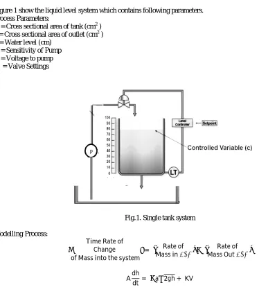
Figure 1 show the liquid level system which contains following parameters. Process Parameters:
A = Cross sectional area of tank (cm2 ) a = Cross sectional area of outlet (cm2 ) h = Water level (cm)
K = Sensitivity of Pump V = Voltage to pump R1 = Valve Settings
Fig.1. Single tank system Modelling Process:
TimeRateof
Change
ofMassintothesystem
= Rateof
Massin low −
Rateof
MassOut low
Adh
Now, we should linearise the model around steady state operating point. Here the nonlinearity arises because of the term √h
By Taylors series of expansion method around steady state hs is given by
h = h + 1
2h ( h−h ) +⋯
For single tank
dh
dt = −
a
A 2g h +
1
2h ( h−h ) +
KV A
Let,
T = A
a 2h
g
dh
dt = f(h, V)
Linear approximation of this equation can be obtained by Taylors series of expansion and truncating after first order system. The reference point for linearization is the normal steady state operating point (h ,V, )
f(h, V) = f h ,V , +
∂f
∂h (h− h ) +
∂f
∂h (V− V ) … … … (1)
But steady state corresponds to f (h ,V, ) = 0 and deviation variables arises out of Taylors series of expansion.
h′ = h− h And V′= V− V
dh′
dt =
d
dt(h− h ) =
∂f
∂hh
′) h + ∂f
∂VV
′) V … … … (2)
Let,
a =
h h and c = V
Now,
a = ∂f
∂h h =
∂
∂h −
a
A 2gh =
−a
A g 2h
and
c = ∂f
∂V V =
∂ ∂V KV A = K A d
dt (h−h ) =
−a
A g
2h (h− h ) +
K
A (V− V ) … … … (3)
Above equation can be written as
dx
dt =
−a
A g
2h x +
K
Au
T = A a
2h g
So we can write above equation as
dx
dt =
−1
T x +
K
Au
Thus we get the state model
ẋ= Ax +̇ Bu
ẋ = −1
T x +
K
A u … … … (4)
̇
And Output
y = Cx + Du y = K x + 0 … … … (5)
Equation (4) and (5) are the state model equations.
IV.DESIGNOFPIDCONTROLLER
Process Parameters A = 66.242 cm2 a= 3.14 cm2 g = 981 cm K = 5.054 V = Voltage
h = 1.4
T = = 1.127
ẋ= −1
T x +
K
A u
ẋ = [−0.886]x + [0.076]u … … … (6)
y = [0.5]x … … … (7)
Obtain Transfer function from state space
G(s) = c[IS−A] . B + D
G(s) = 0.038
S + 0.886
Ziegler Nichols Method is used for controller setting which is based on adjusting closed loop until steady state oscillations occur [3]. By Using Z-N Method
G(s) = 0.038K
S + 0.886 + 0.038K
And
Following are the parameters of PID controller
K = 13.98, T = 7.088, T = 1.772
V. EXPERIMENTALRESULTS
Fig.2. Simulink model of system
The Simulink model of single tank water level control system using PID controller for obtaining the step response is mentioned in figure 2. Here the Z-N method is used find the PID parameters. Transfer function in this system represents the mathematical model of single tank system.
Fig.3 Simulation of step input
Simulation results of liquid level control system with PID controller are shown in figure 3. Transfer function of a system is obtained after modelling of liquid system.
0 10 20 30 40 50 60 70 80 90 100 0.4
0.5 0.6 0.7 0.8 0.9 1
Step Response
Time (seconds)
A
m
p
lit
u
d
e
Figure 4 shows tunned and block parameters of PID controller. The performance parameters like rise time, settling time, overshoot, gain margin and closed loop stability etc were also mentioned in figure 4.
Figure 5 represents the graphical representation of performance parameters of PID controller. PID controller gives good control over the process.
Fig.6.Step response of system
For single tank system inlet flow rate is 80 LPH and step input given 90 LPH. The figure 6, Shows step input response of actual level system.
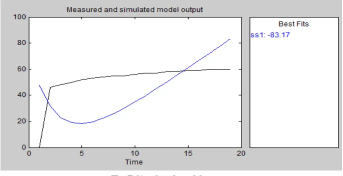
Fig.7.Simulated model output
Best fit graph of designed system is shown in figure 7. This is obtained by using MATLAB identification tool box. The obtained best fit results are obtained from practical values.
VI. CONCLUSION
it may be concluded that the PID controller is the most effective controller that eliminates the offset of the proportional mode and still provides fast response. This system gave us 83.17 % best fit.
REFERENCES
[1] J. Swder, G. Wszoek, W. Carvalho, “Programmable Controller Design Electro pneumatic systems”, Journal of Material Processing Technology 164-1655 (2005) 14659-1465
[2] William L. Luyben, “Process Modelling, Simulation and Control for Chemical Engineers”, Second Edition, Mc-Graw Hill publication [3] C. D. Johnson, “Process Control Instrumentation Technology”, Seventh Edition, Pearson Education, New Delhi 2003.
[4] Dale E. Seborg, Thomas F. Edgar, Duncan A. Mellichamp, “Process Dynamics and Control”, Second Edition, Willey Publication. Manual: ECON DT 9812.
[5] G. Stepnopoulos, “Chemical Process Control: An Introduction to Theory & Practice”, Prentice Hall Of India.
[6] Mostafa A. Fellani, Aboubaker M. Gabaj, “PID Controller Design for two tanks liquid level control system using MATLAB”, International journal of Electrical and Computer Engineering, Vol. 5 No.3 June 2015,pp, 436-442.
[7] Miral Changela, Ankit Kumar, “Designing of controller for two tank system”, International Journal of Science and Research., ISSN 2319-7064.
[8] S.Janarthanan, K.N.Thirukkuralkani, S.Vijayachitra, “Performance Analysis of Non-Integer Order PID Controller for Liquid Level Control of Conical Tank System”, IEEE , ISBN No.978-1-4799-3834-6/14
[9] Anca Maxim, Clara M.Ionescu, Cosmin Copot, Robin De Keyser “Multivariable Model-Based Control Strategies for Level Control in a Quadruple Tank Process”, IEEE, 978-1-4799-2228-4/13.
[10] W. Bequette, Process Control: Modeling, Design and Simulation, Prentice Hall Professional, 2003. [11] K. Ogata ,“Modern Control Engineering” Fourth Edition, Pearson Publication.