ISSN(Online): 2319-8753 ISSN (Print): 2347-6710
I
nternational
J
ournal of
I
nnovative
R
esearch in
S
cience,
E
ngineering and
T
echnology
(An ISO 3297: 2007 Certified Organization)
Website: www.ijirset.com
Vol. 6, Issue 7, July 2017
Modeling and Analysis of DPFC to Improve
Power Quality
Ishwar K. Charawande1, S.S. Dhamse2
P.G. Student, Department of Electrical Engineering, Government College of Engineering, Aurangabad, Maharashtra, India1
Associate Professor, Department of Electrical Engineering, Government College of Engineering, Aurangabad, Maharashtra, India2
ABSTRACT: Over the last few decades power demand by different consumers is rapidly increasing. This increase in power demand is due to excess usage of electrical power for the various types of loads. Also power quality issues are arising due to nonlinear loads connected in complex power network; as a result quality of power system of power gets decreases. Major power quality problems are under voltage, over voltage and interruptions. In this paper transmission network’s power quality is improved by implementing Distributed Power Flow Controller (DPFC). DPFC is nothing but the improvised or modified Unified Power Flow Controller (UPFC). For achieving DPFC from UPFC a common DC-link between shunt and series converter is eliminated and also instead of a single large size three-phase converter, a single phase converter of small size but multiple number are used. The system is implemented using MATLAB software and results are discussed.
KEYWORDS:DPFC, FACTS, Power Quality, UPFC.
I. INTRODUCTION
In recent years, because of increase in utilities, the power demand also increased drastically on transmission network and this will continue increase. The power quality is supply of perfect voltage and frequency within limited tolerances with pure sinusoidal wave [1]. The performance of electrical apparatus on delivering or consuming the electric power is nothing but the power quality [2]. Failure of power is caused by deviation in current, voltage or frequency hence from customer viewpoint, power quality is determined on changes in current, voltage and frequency [3]. Dynamic Voltage Restorer (DVR) and Flexible AC Transmission System (FACTS) are power electronics converter also known as custom power devices, both distribution and transmission side controller, which are used for solving the power quality issues. Generally to improve customer power quality for medium to low levels custom power devices like DVR are used [4]-[5].
Grid Short circuit, inrush currents which develop during start of bulky machines or switching operations in grid these events leads to the power quality issues. Voltage sag, voltage swells and interruptions also occur on transmission line which are again can be considered or responsible for power quality issue [6]. FACTS devices such as synchronous static compensator (STATCOM)and Unified Power Flow Controller (UPFC) are used to mitigate the above mentioned power quality issues. STATCOM and Static Synchronous Series Compensator (SSSC) attached through a same dc link results into UPFC. The purpose of adding dc link is to allow flow of real power in both the direction between STATCOM’s shunt output terminal and SSSC’s series output terminal as shown in figure 1. Failures of one converter will affect the whole system due to the dc storage capacitor which is a common dc link. System become costly if redundant backups are used to achieve a dependable power system. Hence UPFC is not used widely because of failure redundancy and high cost [7]-[8].
ISSN(Online): 2319-8753 ISSN (Print): 2347-6710
I
nternational
J
ournal of
I
nnovative
R
esearch in
S
cience,
E
ngineering and
T
echnology
(An ISO 3297: 2007 Certified Organization)
Website: www.ijirset.com
Vol. 6, Issue 7, July 2017
exchanged in transmission line using DPFC numerous small size 1
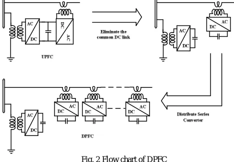
series converters instead of single series converter including one shunt converter results in derived version of UPFC called DPFC [10].Fig. 1 UPFC
Line impedances, transmission and bus voltage magnitude of power system are simultaneously adjusted by DPFC having same capability as UPFC [11]. DPFC has lower cost with enhanced reliability than conventional FACT devices hence it is recently presented in power flow devices in FACTS family.
II. DISTRIBUTED POWER FLOW CONTROLLER
The basic concept in DPFC principle is nothing but the introduction of distribution of series converter and elimination of common voltage DC-link in UPFC. Active power swap over is achieved by using 3rd harmonic current.
Fig. 2 Flow chart of DPFC A. Construction of DPFC
ISSN(Online): 2319-8753 ISSN (Print): 2347-6710
I
nternational
J
ournal of
I
nnovative
R
esearch in
S
cience,
E
ngineering and
T
echnology
(An ISO 3297: 2007 Certified Organization)
Website: www.ijirset.com
Vol. 6, Issue 7, July 2017
Fig. 3 Construction of DPFC
B. Principle of operation
Two methods can be employed for active power flow a) Eliminated dc link real power exchange
b) By using 3rd harmonic components in each phase
The compensation technique and reactive power flow are similar to UPFC.
a) Eliminated dc link real power exchange
Transmission line act as the common link between series and shunt ac terminals within DPFC that’s why real power can be swap over through converter terminals. Power theory of non-sinusoidal components is basic concept behind this method. Fourier analysis states that, a non-sinusoidal signal such as current and voltage can be expressed as sum of sinusoidal functions with different amplitudes calculated at varying frequencies hence average value of real power is obtained. Since of terms with varying frequencies for the integrals of all cross product are zero, the real power is represented by equation (1):
1
cos
j
j j j
i
v
P
(1)For jth harmonic frequency Vjand Ij are the voltage and current and the angle between the voltage and current is
represented as
j. Eqn (1) shows real power can be separated at other frequencies i.e. the voltage and current hasdifferent values at different frequencies it means that their values at one frequency are not influenced by values at other frequency. In the absence of power source converters can deliver or draw real power. When we see from the point of view as mentioned above for DPFC can inject current into the grid at harmonic frequency and absorb the real power from the grid at fundamental frequency. DPFC converters which are in series at harmonic frequency generate a voltage and from harmonic components absorb active power so that required amount of real power is maintained. Through the T-line harmonic current will flow. When we assume a converter as lossless then the generated voltage at nominal frequency is same as harmonic power absorbed. Y-∆ transformers are generally used for blocking the zero sequence
harmonics, which are used for voltage level change hence 3rd harmonic sequence are used to swap over real power through transmission line in the converters.
Within the DPFC there are high pass filter which allows only harmonic components and blocks fundamental frequency components hence provide return path for harmonic components. Series and shunt converter provide closed path to the flow of harmonic current, the high pass filter and ground. The 3rd harmonic frequency components are chose for the exchange of active power in DPFC because of their unique characteristic.
b) By using 3rd harmonic components in each phase
The identical nature of the third harmonic in each phase In a system of a three-phase i.e. zero sequence components proved to be an advantage as Y-∆ transformers have ability to stop zero sequence components naturally so power
ISSN(Online): 2319-8753 ISSN (Print): 2347-6710
I
nternational
J
ournal of
I
nnovative
R
esearch in
S
cience,
E
ngineering and
T
echnology
(An ISO 3297: 2007 Certified Organization)
Website: www.ijirset.com
Vol. 6, Issue 7, July 2017
DPFC. But, lowest frequency has to be selected among all zero sequence harmonics hence third harmonic is used. Exchanged active power Pi at ith harmonic frequency and converter generated voltage is related as
shj sej
jj se j sh j
X
V
V
P
, ,sin
,
, (2)Where Xj is the jth frequency line impedance, and
V
se,j andV
sh,j are the j thharmonic voltage magnitudes of the series and shunt converters,
sh,j
se,j
is the angle difference between the two voltages. The line with requires larger voltages to swap over the equal amount of real power. High voltage at the converters is the result of high impedance resulted from high frequencies within the transmission line as transmission line is mostly inductive in nature and proportional to frequency. Consequently, lowest frequency third harmonic is selected with zero sequence harmonic [12].III.CONTROL CIRCUIT FOR DPFC
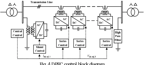
Fig. 4 DPFC control block diagram
Series control, shunt control and central control are three different types of controllers to control multiple converters in DPFC as shown in figure 4. The shunt and series control are accountable for keeping their own converters parameters and are local controllers. At the power system level the central control takes concerned about the DPFC functions. Each controller’s function is listed.
A. Central Control
By the central control of the DPFC both the shunt and series converters reference signals is generated. On the power system level it is paying attention on the DPFC tasks, such as power flow control, power oscillation low frequency damping, and asymmetrical components balancing. Voltage reference signals is given by the central control According to the system requirement, corresponding for the series converters and shunt converter’s reactive current signal. All the reference signals are at the fundamental frequency which are generated by the central control.
B. Series Control
Each series converter is provided with series controller. By using the third harmonic frequency components, the capacitor dc voltage of its own is maintained this is the main use of this series controller the and to generate series voltage at the fundamental frequency that is approved by the central control. Generally, for injecting natural and 3rd order harmonic currents into the line these series controllers have third order band pass filter and first order low pass filter.
C. Shunt Control
ISSN(Online): 2319-8753 ISSN (Print): 2347-6710
I
nternational
J
ournal of
I
nnovative
R
esearch in
S
cience,
E
ngineering and
T
echnology
(An ISO 3297: 2007 Certified Organization)
Website: www.ijirset.com
Vol. 6, Issue 7, July 2017
Table 1: Parameter Table Symbol Description Value
Vs Nominal voltage of grid s 220V
Vr Nominal voltage of grid r 220V
Transmission angle between grid s and r 1Ish,ref,3
Reference 3rd harmonic current injected by shunt converter 3A
fsw Triggering frequency for the shunt and
series converter 6kHz
IV.ADVANTAGES OF DPFC OVER UPFC
The DPFC is to be assign as a UPFC that employ the Distributed Flexible AC Transmission System conception and the theory of exchange power through the harmonic frequencies. Therefore, the DPFC have the merits over the UPFC and the Distributed Flexible AC Transmission System, which are as follows
a) High control capability: All parameters of the power system can controlled by the DPFC line impedance, transmission angle and the bus voltage. The common dc link is eliminate which simply enables for separate installation of DPFC parameters. Because of high control capability the DPFC can also used for the improve power quality and the system stability, just like low frequency power oscillation damping, voltage sag or balancing asymmetry.
b) High reliability: series converter gives the improved reliability because of the redundancy of the converter. In addition, the shunt and series converters are separated from each other and because of that if failure happens at one place the will not disturb the other system parameters. If the failure happened in the series converter, the converter will be short circuited by using bypass protection, because of that network having little influence. If the shunt converter fails, i.e. shunt device get trips as well as series device will stop giving real power compensation and it will operate as the Distributed FACTS controller.
c)Economical cost: Because of the one large size converter is having more cost than the single phase converters and rating is also lower. Therefore, the series converters do not need any high voltage isolation in transmission line. Also the each converter having the small power rating and it can produce power easily in series production lines.
V. RESULTS AND DISCUSSION
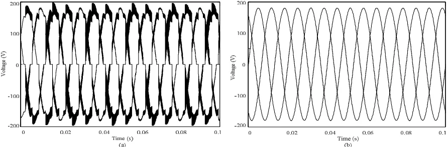
The principle and operation of Disturbed Power Flow Controller is presented using MATLAB/SIMULINK. The simulation waveforms of load voltages of system without DPFC and with DPFC as given in figure 5(a) and 5(b).
ISSN(Online): 2319-8753 ISSN (Print): 2347-6710
I
nternational
J
ournal of
I
nnovative
R
esearch in
S
cience,
E
ngineering and
T
echnology
(An ISO 3297: 2007 Certified Organization)
Website: www.ijirset.com
Vol. 6, Issue 7, July 2017
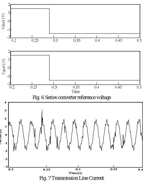
By using DPFC the change in injected voltage the series converter controls the flow of power in the transmission line at nominal frequency. Figures illustrated the step response of the DPFC Reference voltage for the series converters, series converter voltage, line current, real and reactive power inserted by the series converter at nominal frequency.
Fig. 6 Series converter reference voltage
Fig. 7 Transmission Line Current
To check that if series converter can able to introduce or absorb real and reactive power from the grid at nominal frequency, the power is computed from the exact voltage from system in fig. 6 and current in fig. 7.
Fig. 8 shows the real and reactive power inserted by the series converter. It can be concluded series converters are able to exchange real and reactive power in the grid at nominal frequency.
ISSN(Online): 2319-8753 ISSN (Print): 2347-6710
I
nternational
J
ournal of
I
nnovative
R
esearch in
S
cience,
E
ngineering and
T
echnology
(An ISO 3297: 2007 Certified Organization)
Website: www.ijirset.com
Vol. 6, Issue 7, July 2017
Table 2: Result Table
Configuration Load voltage THD (%) System before compensation 10.70%
System after compensation 0.34%
VI.CONCLUSION
In this paper concept of DPFC is presented. The DPFC is modification of UPFC, it can achieve by eliminating dc link among the converters having in the UPFC, dc link is transmitted the power between the converters shunt as well as series. Now in DPFC, this real power is exchange in the transmission line using 3rd harmonic frequency component. Both devices have the control of the transmission line impedance, load angle, and the bus voltage. The series converter is applying the distributed FACTS concept, which adopts the several
1
converters in place of the one bulky size converter. Because of this the consistency of DPFC is rises and the prolixity of series converters is also rises, which has been affirmed from the THD values of load voltages without DPFC and with DPFC as given in Table 2. Cost of DPFC will get reduced as compare to UPFC, as we don’t required high voltage separation at series converter that’s why the rating of components is low.REFERENCES
[1] Y.H. Song and A. Johns, Flexible ac Transmission Systems (FACTS) (IEE Power and Energy Series), vol. 30. London, U.K.: Institution of Electrical Engineers, 1999.
[2] Alexander Eigels Emanuel, John A. McNeill “Electric Power Quality”. Annu. Rev. Energy Environ 1997, pp. 263-303.
[3] Zhihui Yuan, Sjoerd W.H de Haan, Braham Ferreira and Dalibor Cevoric “A FACTS Device: Distributed Power Flow Controller (DPFC)” IEEE Transaction on PowerElectronics, vol.25, no.10,October 2010.
[4] S. Masoud Barakati, Arash Khoshkbar Sadigh and Ehsan Mokhtarpour, “Voltage Sag and Swell Compensation with DVR Based on Asymmetrical Cascade Multicell Converter” , North American Power Symposium (NAPS), pp.1–7,2011
[5] N. G. Hingorani and L. Gyugyi, Understanding FACTS: Concepts and Technology of Flexible AC Transmission Systems, New York: IEEE Press, 2000.
[6] Y. Zhihui, S.W. H. de Haan, and B. Ferreira, “Utilizing distributed power flow controller (DPFC) for power oscillation damping,” IEEE Power Energy Soc. Gen. Meet. (PES), pp. 1–5, 2009.
[7] Zhihui Yuan, Sjoerd W.H de Haan and Braham Ferreira “DPFC control during shunt converter failure” IEEETransaction on Power Electronics
2009.
[8] Y. Zhihui, S. W. H. de Haan, and B. Ferreira, “DPFC control during shunt converter failure,” IEEE Energy Convers. Congr. Expo. (ECCE) 2009, pp. 2727–2732.
[9] M. D. Deepak, E. B. William, S. S. Robert, K. Bill, W. G. Randal, T. B. Dale, R. I. Michael, and S. G. Ian, “A distributed static series compensator system for realizing active power flow control on existing power lines” IEEE Trans. Power Del., vol. 22, no. 1, pp. 642–649, 2007. [10] D. Divan and H. Johal, “Distributed FACTS- A new concept for realizing grid power flow control,” IEEE 36th Power Electron. Spec. Conf. (PESC), pp. 8–14, 2005.