A Steganography Technique Based On
Chaotic LSB and DWT
Nirmal Kaushik, Kalpana Sheokand
M. Tech Student, Dept. of ECE, YMCA University of Science & Technology Faridabad, Haryana, India
Assistant Professor, Dept. of ECE, University of Science & Technology Faridabad, Haryana, India
ABSTRACT: This paper presents a system which is more secure data hiding technique. In modern age in which data is conveyed through digital medium, the protection of data is top priority concern for any organization. Steganography is a technique of hiding the secret information in a cover media. This cover media can be an image, a video file or any media. This Stego file is transmitted over the channel and the unintended user cannot even suspect the presence of secret message. The image stegnography technique takes the advantage of limited power of human vision system. It uses image as a cover media for embedding secret images. The most important requirement for a stegnographic algorithm is to be imperceptible while maximizing the size of the payload. In this project a method is proposed to encrypt the secret bits of message based on chaos theory(applying spacial domain stegnography ) and then applying frequency domain stegnography to the same before embedding into the cover image. A 3-3-2 LSB insertion which ensures high PSNR and discrete wavelet transform(DWT) which ensures that the system is immune to attacks. The use of MATLAB tool in this paper provides a complete design capture and simulation solution that provides accuracy and convergence.
KEYWORDS: Image Steganography, Dynamic System, Chaotic Maps, Human Visual System, Cover Image , stegno image, secret image, LSB and DWT.
I.INTRODUCTION
variable space, a method for searching of global minima in optimization problems was introduced [11]. However, there are no mathematical proofs about the benefits of using chaotic sequence [12]. Confidentiality, non-periodicity, more randomness and easy implementation are the main advantages of using chaos theory in steganography technique. It is robust for the image processing techniques like image cropping compression, etc. In [18] the logistic map is used to generate a sequence as the watermark. The logistic map is used to shuffle the bits order of the secret message in [19].Chaotic property is used to determine the initial choice of the optimization parameters both in starting step and the mutations applied when a convergence to local minima occurred. In [21] the proposed technique uses a fractal image as the host image and then generated a random like sequence by chaotic map as the reference for embed positions, and uses a wavelet transform to realize the embedding procedure. A Haar wavelet transform is used in [22] to decompose the image into averaging and differencing components. In [23] once the message is embedded within the cover image, it is encrypted using triple-key chaotic image encryption. A hybrid model of chaotic function and cellular automata is presented in [24]. By using an N-bits mask pixel position is determined in the cover image for hiding one bit of secret message. The mask is generated in each stage by cellular automata and logistic map function. In [25] a new technique is presented based on chaotic steganography and encryption text in DCT domain for color images.
The rest of the paper is organized as follows. In Section 2 the Chaos LSB steganography technique has been described. In Section 3C-LSB technique is illustrated. In Section 4 DWT HAAR technique is explained. The proposed algorithm using a simulated environment is given in Section 5. Experimental results and performance evaluation are discussed in Section 6.
II.CHAOS BASED LEAST SIGNIFICANT BIT STEGANOGRAPHY (C-LSB)
In the chaotic method the logistic chaotic map is used to encrypt the secret message and thenembedded into the cover image using the base embedding technique.The logistic map is used to encrypt the secret data bits before embedding to enhance the security of the image steganography as the secret data bits are not embedded directly into the cover image. This technique adopts logistic mapping method to generate chaotic sequence.
TECHNIQUE
In this technique eight bits of secret data are considered for embedding at a time in the LSBof RGB pixel value of the carrier image in 3, 3, 2 order respectively. Thus first three bits of thesecret message are concealed inside three (03) bits of LSB of Red pixel, next three bits in the three (03) bits of LSB of Green pixel. The remaining two bits of secret message are concealed in two (02) bits of LSB of Blue pixel. Theparticular distribution pattern is taken considering that the chromatic influence of blue to the human eye is more than that of red and green pixels [27].
The base technique of image steganography algorithm is enumerated bellow: Step 1: Find four LSB bits of each RGB pixels of the cover image.
Step 2: Embed the eight bits of the secret message into 4 LSB of RGB pixels of the cover image in the order of 3, 3, 2 respectively.
Step 3: Form the stego image.
Whereas the decoding algorithm is explained bellow:
Step 1: Find four LSB bits of each RGB pixels of the stego image.
Step 2: Retrieve the bits of the secret message from LSB of RGB pixels of the stego image in the order of 3, 3, 2 respectively.
Figure 1: Base embedding technique showing 1 Byte of secret data embedded inside 4 bits of LSB in 3, 3, 2 order into corresponding RGB pixels of carrier image.
III. ILLUSTRATIONOF C-LSB TECHNIQUE
Consider a secret image of resolution H×W where H is the height and W is the width of the secret. The secret image is divided into eight equal parts such that each part will have resolution of M×W where M is the height and W is the width of this part of the image. Thus the total number of pixels in each secret image part is M×W and each pixel has three 8 bit components R (Red), G (Green) and B (Blue). So the total number of components (N) in this secret image part is N=M×W×3. Now using the logistic map equation a logistic chaotic sequence of N real numbers is generated as {Xk} where k = 0, 1, 2, … N-1. The initial values of μ and X are considered as 3.60 and 0.65 respectively, as the logistic map stands in chaotic region when 3.5699456 < μ ≤ 4 and 0 < Xk < 1 [6]. With the initial values of μ and X considered as 3.60 and 0.65 the logistic chaotic sequence of N numbers is shown as bellow: {Xk} = {0.819000, 0.533660, 0.895921, 0.335687, 0.802805, 0.569913, 0.882404, 0.373563, …} Next the arithmetic mean of these N real numbers is considered as threshold T. Here = Σ= 0.646400 for the first secret image part. Thus for each k=0, 1, 2, …N-1 if XK ≥ T then Bk = 1 otherwise 0. Thus for the first secret image part the binary sequence {Bk} is generated as bellow:
{Bk} = {1, 0, 1, 0, 1, 0, 1, 0, ….} For each 8 bit component Ck(k=0,1,...N-1) of the secret image part an XOR operation of each bit of Ck is done with a single bit of Bk in the binary sequence e.g. if Ck = 01010000 and Bk =1 then Ck]’ = 10101111. Where Ck ]’ is the encrypted component. Repeat this procedure until all such components of the secret image part is encrypted. The same procedure is followed for the remaining seven parts of secret image. Each part is encrypted using different logistic maps as given in Equation 1 with different initial conditions of and X. The pair of values (μ, X) considered are (3.60, 0.65), (3.61, 0.66), (3.62, 0.67), (3.63, 0.68), (3.64, 0.69), (3.65, 0.70), (3.66, 0.71), (3.67, 0.72). Finally the encrypted parts are merged to form the encrypted secret image. At last embed each eight bit component of the encrypted secret image into 4 bits of LSB , thus forming a stego image. An algorithm of the proposed encoding and steganography is given in later Section.
sequence {Bk} is generated where k = 0, 1, 2, … N-1. For each 8 bit component Ck’ of the encrypted secret image part where k=0, 1, 2, ... N-1 XOR each bit of the component with a single bit Bk in the binary sequence e.g. if Ck’ = 10101111 and Bk =1 then Ck =01010000. Repeat this procedure until all the encrypted eight bit components of the secret image part are decrypted. This process is repeated for the remaining seven parts with the different initial conditions for logistic as assumed during encoding. After decrypting all the encrypted image parts the parts are merged to form the original secret image.
IV. HAAR DWT TECHNIQUE
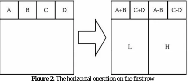
The frequency domain transform we applied in this research is Haar-DWT, the simplest DWT [17]. A 2-dimensional Haar-DWT consists of two operations: One is the horizontal operation and the other is the vertical one. Detailed procedures of a 2-D Haar-DWT are described as follows:
Step 1: At first, scan the pixels from left to right in horizontal direction. Then, perform the addition and subtraction operations on neighboring pixels. Store the sum on the left and the difference on the right as illustrated in Figure 2. Repeat this operation until all the rows are processed. The pixel sums represent the low frequency part (denoted as symbol L) while the pixel differences represent the high frequency part of the original image (denoted as symbol H).
Figure 2. The horizontal operation on the first row
Step 2: Secondly, scan the pixels from top to bottom in vertical direction. Perform the addition and subtraction operations on neighboring pixels and then store the sum on the top and the difference on the bottom as illustrated in Figure 3. Repeat this operation until all the columns are processed. Finally we will obtain 4 sub-bands denoted as LL, HL, LH, and HH respectively. The LL sub-band is the low frequency portion and hence looks very similar to the original image.
Figure 3. The vertical operation
V.ALGORITHM OF PROPOSED TECHNIQUE
Sender’s side
The embedding technique is explained by the following steps: Step 1: Take cover image, secret image.
Step 2: Determine the size of the cover and secret image. Step 3: Break the secret image into eight parts.
Step 4: For each of the eight parts generate a bit sequence by the procedure as described in Section 3.
Step 5: Encrypt eight bits of the secret image part by XOR operation with a single bit in the bit sequence generated for the corresponding secret image part obtained from step 4.
Repeat this step for each of the secret image parts.
Step 6: Embed the encrypted eight bits of the secret image into 4 bits of LSB of RGB pixels of the cover image in the order 3, 3, 2 respectively until all the bits of the encrypted secret image are embedded.
Step 7: Take another cover image of larger size.
Step 8: Apply DWT ‘haar’ transform on it as explained in section 4 from which LL,LH,HL,HH regions are obtained. Step 9: Embed Output image obtained by applying LSB technique in LL plane region.
Step10: Apply inverse haar DWT transform Step 11: Transmit the stego image.
Step 12: Stop. Reciever’s side
The decoding algorithm consists of eight steps as follows: Step 1: Input stego image.
Step 2: Read required information from stego image. Step 3:Apply DWT haar transform
Step 3: Retrieve the bits from LSB of RGB pixels of the stego image in the order 3, 3, 2 respectively to get the encrypted secret image.
Step 4: Divide the encrypted secret image into eight parts.
Step 5: For each of the eight parts generate a bit sequence the procedure as described in Section 3.
Step 6: Each of the eight bits of encrypted secret image part will be XORed with a single bit in the bit sequence obtained from step 5 to construct original eight bits of the secret image. Repeat this step for each of the encrypted image parts.
Step 7: Get the secret image.
Step 8: Compare the received secret image with original secret image. Step 9: Stop.
VI. EXPERIMENTAL RESULTS AND CONCLUSION
This paper includes comparing results based on PSNR and MSE values. This paper presents a art of combining the two different security technique namely chaos LSB and DWT For performance evaluation four pixel values are considered. Details of each are given in Table 1. The details of the secret image are also given in Table 1. Table1 shows that the proposed technique is good to achieve high PSNR , low MSE along with a more secured system.
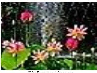
Figure 4,5,6 respectively shows the secret image,cover image,image after applying chaos LSB. Figure 8 shows the final stego image after applying DWT.
Fig6: image after applying Chaos LSB
Fig7: cover image for DWT Haar
Cover image (H*W)
Secret image size
Chaos LSB (3,3,2) PSNR
Proposed technique PSNR
Chaos LSB (3,3,2) MSE
Proposed technique MSE
64*64 32*32 43.09 67.5792 1.5 0.0114
128*128 32*32 47.08 67.7374 1.32 0.0109
256*256 32*32 49.12 68.1383 1.00 0.01
512*512 32*32 56.11 68.2823 0.15 0.0097
1024*1024 32*32 58.45 72.2278 0.125 0.0039
Table1: Results taking different pixel values
VII. CONCLUSION
CHAOS technique ensures randomness and hence ensures more entropy. LSB 3,3,2 technique is used in this paper due to its complexity and high PSNR value whereas DWT ensures high security and makes system more prone to attack. Future work in this field can be done by using some hybrid technique in order to achieve more security which is the need of a communication system.
REFERENCES
1. Jigar Makwana, S.G Chudasama “Dual Steganography: A New Hiding Technique for Digital Communication”International Journal of Advanced Research in Electrical, Electronics and Instrumentation Engineering Vol. 5, Issue 4, April 2016.
2. Sumeet Kaur, Savina Bansal, and R. K. Bansal., “Steganography and Classification of Image Steganography Techniques”. International Conference on Computing for Sustainable Global Development.978-93-80544-12-0/14 2014 IEEE 2014
3. Mennatallah M. Sadek & Amal S. Khalifa & Mostafa G. M. Mostafa. “Video steganography: a comprehensive review” DOI 10.1007/s11042- 014-1952-z Springer Science New York 2014
4. Wang Tianfu, K. Ramesh Babu., “Design of a Hybrid Cryptographic Algorithm”. International Journal of Computer Science & Communication Networks,Vol 2(2), 277-283
5. Ramadhan J. Mstafa, Khaled M. Elleithy., “A high payload video steganography algorithm in DWT domain based on BCH codes(15,11)”, 978-1-4799-6776-6/15 2015 IEEE
6. Vishnu S babu and Prof. Helen K J. “A Study on Combined Cryptography and Steganography:” International Journal of Research Studies in Computer Science and Engineering Volume 2, Issue 5, May 2015, PP 45-49 ISSN 2349-4840 (Print) & ISSN 2349-4859(online).
7. Amr A. Hanafy, Gouda I. Salama and Yahya Z. Mohasseb “A secure covert communication model based on video steganography” 11331. 978-1-4244-2677-5 IEEE 2008.
BIOGRAPHY
Nirmal kaushik is a mtech student in Electronics and communication engineering, YMCA university of science and technology. She received Bachelor of technology degree(B.tech) in 2014 from Manav Rachna College of Engineering, Faridabad.