Available online: http://edupediapublications.org/journals/index.php/IJR/ P a g e | 1285
A Novel Modulation Technique Algorithms on Channel
Coding and decoding
Nimmala Narendar
1&Mr.K.Baskar
21
M-Tech Dept. ECE, SwarnaBharathi College of Engineering, Khammam
2
HOD&Associative professorDept. ECE, SwarnaBharathi College of Engineering, Khammam
Abstract
Orthogonal Frequency Division Multiplexing (OFDM) hasgained increased interest due to its robustness
against multipathinterference and high spectrum efficiency. OFDM is asuitable candidate for high data
rate transmission with forwarderror correction (FEC) methods over wireless channels. In thispaper, the
system throughput of a working OFDM system hasbeen enhanced by channel coding technique like
Reed Solomoncode& Turbo Code. Forward Error Correcting codes are a newclass of codes that can
achieve exceptional error performanceand energy efficiency at low signal-to-noise ratio. The simulation
is made with the development of Models in theSIMULINK & computer program written in MATLAB
sourcecode on the random data under additive white Gaussian noise(AWGN) channel. The simulation
results of estimated Bit errorrate (BER) show that the implementation of RS code with ½ -rated under
QPSK modulation technique is highly effective tocombat inherent interference in the communication
system.Fordecoding of Turbo code, MAP decoding algorithm is used. Incase of Turbo code BER
performance is substantially improvedby increasing number of iterations used in the decoding process.
Keywords:Channel Coding, Channel, decoding Algorithms, Modulation Technique etc.
1.
Introduction
Orthogonal Frequency Division Multiplexing
(OFDM) is a Multi-Carrier Modulation
technique in which a single high rate
stream is divided into multiple low rate
data-streams and is modulated using sub-carriers
which are orthogonal to each other. Some of the
main advantages of OFDM are its multi-path
delay spread tolerance and efficient spectral
usage by allowing overlapping in the frequency
domain. OFDM is symbol based, and can be
thought of as a large number of low bit rate
carriers transmitting in parallel. All these
carriers transmitted using synchronized time and
Available online: http://edupediapublications.org/journals/index.php/IJR/ P a g e | 1286
This is to ensure that the orthogonal nature of
the structure is maintained.
However, in the present study, an effort has
been made merely to concatenate the various
channel encoding codes to improve the reliable
reception performance of an OFDM wireless
communication system under different digital
modulation schemes such as QPSK, 32-QAM,
64-QAM. In almost all applications of
multi-carrier modulation, satisfactory performance
cannot be achieved without the addition of some
form of channel coding. In wireless systems
subjected to fading, extremely high
signal-to-noise ratios are required to achieve reasonable
error probability. In addition, interference from
other wireless channels is frequently severe. If
channel coding is applied, the performance of
OFDM is expected to be significantly improved
through time diversity of channel coding as well
as through inherent frequency diversity of the
OFDM [1] [2].
2.
Related Work
Orthogonal frequency division multiplexing
(OFDM) is nowadays widely used for achieving
high data rates as well as combating multipath
fading in wireless communications. In this
multi-carrier modulation scheme data is
transmitted by dividing a single wideband
stream into several smaller or narrowband
parallel bit streams.
Each narrowband stream is modulated onto an
individual carrier. The narrowband channels are
orthogonal vis-à-vis each other, and are
transmitted simultaneously. In doing so, the
symbol duration is increased proportionately,
which reduces the effects of inter-symbol
interference (ISI) induced by multipath
Rayleigh-faded environments. The spectra of
the subcarriers overlap each other, making
OFDM more spectral efficient as opposed to
conventional multicarrier communication
schemes.
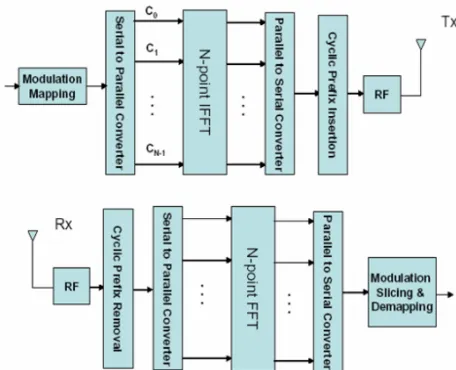
A. OFDM message
The OFDM message is generated in the
complex baseband. Each symbol is modulated
onto the corresponding subcarrier using variants
of phase shift keying (PSK) or different forms
of quadrature amplitude modulation (QAM).
The data symbols are converted from serial to
parallel before data transmission. The frequency
spacing between adjacent subcarriers is Nπ2,
where N is the number of subcarriers. This can
be achieved by using the inverse discrete
Fourier transform (IDFT), easily implemented
as the inverse fast Fourier transform (IFFT)
operation. As a result, the OFDM symbol
generated for an N-subcarrier system translates
Available online: http://edupediapublications.org/journals/index.php/IJR/ P a g e | 1287
At the receiver, the OFDM message goes
through the exact opposite operation in the
discrete Fourier transform (DFT) to take the
corrupted symbols from a time domain form
into the frequency domain. In practice, the
baseband OFDM receiver performs the fast
Fourier transform (FFT) of the receive message
to recover the information that was originally
sent[2].
Figure 1 Basic OFDM System Architecture.
B. Interference
In a multipath environment, different versions
of the transmitted symbol reach the receiver at
different times. This is due to the fact that
different propagation paths exist between
transmitter and receiver. As a result, the time
dispersion stretches a particular received symbol
into the one following it. This symbol overlap is
called intersymbol interference, or ISI. It also is
a major factor in timing offset. One other form
of interference is intermarried interference or
ICI. In OFDM, successful demodulation
depends on maintaining orthogonality between
the carriers. We demodulate a specific
subcarrier N at its spectral peak, meaning that
all the other carriers must have a corresponding
zero spectra at the nth center frequency
(frequency domain perspective). Frequency
offsets lead to this criterion not being met. This
condition can seriously hinder the performance
of our OFDM system. Graph 3.1 below shows
that when the decision is not taken at the correct
center frequency (i.e. peak) of carrier
considered, adjacent carriers factor in the
decision making, thus reducing the performance
of the system [2].
Figure 2 Effect of Frequency Offset
(Maintaining Orthogonality).
Available online: http://edupediapublications.org/journals/index.php/IJR/ P a g e | 1288
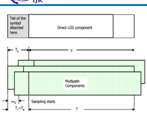
Figure 3. Cyclic Prefix.
OFDM demodulation must be synchronized
both in the time domain as well as in the
frequency domain. Engineers have found a way
to ensure that goal by adding a guard time in the
form of a cyclic prefix (CP) to each OFDM
symbol. The CP consists in duplicates of the end
samples of the OFDM message relocated at the
beginning of the OFDM symbol. This increase
the length T sym of the transmit message without
altering its frequency spectrum.
Where T data is the duration of one data symbol,
and N the number of carriers. The receiver is set
to demodulate over a complete OFDM symbol
period, which maintains orthogonality. As long
as the CP is longer than the channel delay
spread, τ max, the system will not suffer from ISI.
The CP is to be added after the FFT operation at
the transmitter and removed prior to
demodulation. The figure below who’s the
deteriotiation in performance when the CP is
closely matched by the delay spread. The signal
constellation is less tightly grouped, no doubt a
sign of less than accurate decoding.
3.
Implementation
OFDM with forward error correction methods is
most suitable scheme to transmit information
efficiently BER using the Convolution code in
the presence of the fading channel is shown is
explained briefly in the review paper [8]. A type
of Convolution code, called turbo codes that
enable the reduction of errors in noisy channels
without the need to increase the signal power. A
turbo code consists three distinct part namely
encoder, interleave and decoder .The
performance of turbo code depend on the design
& implementation of all the three part. A typical
turbo encoder uses parallel concatenated
convolution codes (PCCC) in which data bits
are coded by two or more recursive systematic
convolution (RSC) coders separated by an
interleave. Turbo code uses two same block of
decoders, the decisions from one component
decoder are passed as input to another decoder
and this process is iteratively done for several
times to get more reliable decisions. The high
bit error correction power of turbo code
Available online: http://edupediapublications.org/journals/index.php/IJR/ P a g e | 1289
and iterative decoding using extrinsic
information at the decoder [8] Turbo coded
AOFDM (TC AOFDM) system combines the
good features of AOFDM with that of turbo
code. Using the iterative property of turbo
codes, a large coding gain is achieved with
respect to an un-coded system.
3.1 TURBO ENCODER:
A Turbo encoder is built using parallel
concatenation of two recursive systematic
Convolution code separated by an interleave. A
typical turbo encoder is shown in figure 1. The
binary input data sequence is represented by dk=
(d1, d2…dN)The input sequence is passed into
the input of the first RSC coder, which
generates Yk-1. For the second RSC, the data
sequence is interleaved using random interleave
in which the bits are output in a pseudo-random
manner. The interleaved data sequence is passed
to a second RSC encoder, generate bit
streamYk2The output code sequence of the turbo
encoder is a multiplexed (and possibly
punctured) stream consisting of systematic code
bitsXk.along with the parity bits of first and
second encoders, Yk1 and Yk2.
Figure 4: Turbo Decoder.
4.
Experimental Work
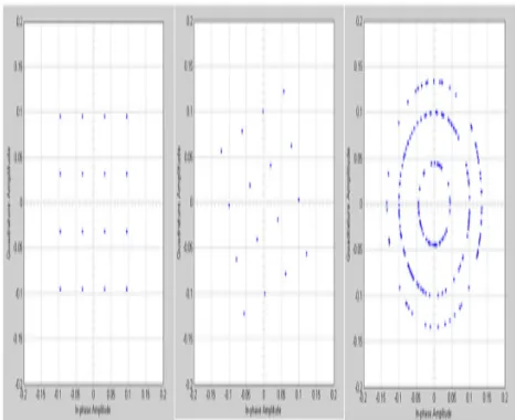
Fig 5: An ideal 16 QAM scatter plot (left)
impaired by a phase offset (middle) and a
Available online: http://edupediapublications.org/journals/index.php/IJR/ P a g e | 1290
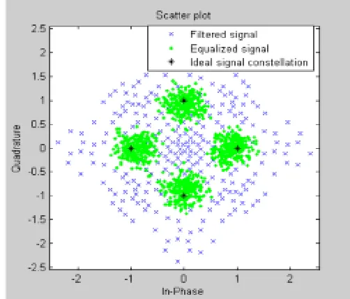
Fig 6: Scatter plot of a QPSK signal that shows
the signal before and after equalization, as well
as the ideal signal constellation.
Fig 7: Received signal scatter plot (left), after
frequency recovery (middle), and after phase
recovery (right).
5.
Conclusion
To conclude, this major project gives the detail
knowledge of a current key issue in the field of
communications named Orthogonal Frequency
Division Multiplexing (OFDM). We focused
our attention on turbo codes and their
implementation. We described the encoder
architecture. In our case, the code is the result of
the parallel concatenation of two identical
RSCs. The code can be punctured in order to
fulfill bit rate requirements. The decoder
succeeded in its duty thanks to the decoding
algorithms that it is built around. We focused
mainly on the study of the MAP.
6. References
[1] M. K. Gupta, vishwas Sharma “To improve
BER of turbo coded OFDM channel over noisy
channel” in Journal of Theoretical and Applied
Information Technology © 2005 - 2009 JATIT.
[2] Lou I Ilunga, Research Work on “Adaptive,
turbo coded OFDM” © 2005.
[3] “Block Turbo Code And Its Application to
OFDM For Wireless Local Area Network” PhD
thesis submitted by Hrudananda Prada.
[4] Liu Na Shi Wenxiao Wu Jiang “A Model of
Turbo Code Based on OFDM-CDMA” in IEEE
journal of 2006.
[5] B.Balaji Naik “Performance Of Turbo
Coded OFDM In Wireless Application” in
partial fulfillment of the requirements for the
award of Master of Technology degree in
Electronics and Communication Engineering
Available online: http://edupediapublications.org/journals/index.php/IJR/ P a g e | 1291
Embedded system” during session 2007-2008 at
National Institute Of Technology, Rourkela
(Deemed University).
[6] Md. Dulal Haque1 , Shaikh Enayet Ullah2 ,
and Md.Razu Ahmed3 “Performance evaluation
of a wireless Orthogonal Frequency Division
Multiplexing system under various concatenated
FEC channel-coding schemes” in Proceeding of
11th International conference on Computer and
Information Technology (ICCIT 2008) 25-27
December, 2008, Khulna Bangladesh.
[7] Arun Agarwal, S. K. Patra, Senior Member
IEEE “Performance prediction of OFDM based
Digital Audio Broadcasting system using
Channel protection mechanisms” in IEEE
journal © 2011.
[8] Jun Zheng, “ Analysis Of Coded OFDM
System Over FrequencySelective Fading
Channels” Phd thesis Submitted to the Office of
Graduate Studies of Texas A&M University
[9] Yung-Chih Tsai, Yeong-Luh Ueng, “A
Tail-biting Turbo Coded OFDM System for PAPR
and BER Reduction” ©2007 IEEE
[10]D. Rajaveerappa, Abdelsalam Almarimi
“RSA/Shift Secured IFFT/FFT Based OFDM
Wireless System” in 2009 Fifth International
Conference on Information Assurance and
Security.
11]Hanjong Kim,” Performance improvement
of Block Turbo Coded OFDM System Using
channel state information” the 23rd international
conference on circuits/systems, computers and
communications (ITCCSCC 2008).
[12] J. Terry, and J. Deiskala, OFDM Wireless
LANs: A Theoretical and Practical Guide, Sams
Publishing, Indiana, 2002.
[13]Haixa Zhang, Feng Zhao, Dongfeng Yuan,
Mingyan Jiang, “Performance of turbo code an
WOFDM system on rayleigh fading channels,”
Proceedings, IEEE, vol. 2, pp.1570-1573, Sept
2003.
[14]J.W. Blakert, E.K. Hall, S.G. Wilson,
“Turbo code termination and interleaver
conditions,” Electronics Letters, Vol. 31, Issue
24, 1995, pp. 2082-2084.
Authors Profile
Name: NIMMALA NARENDAR
B-Tech in SwarnaBharathi College Of
Engineering, Khammam, percentage is 72.46% ,
year of completed April 2014.
M-Tech [ECE] (Electronics and Communication
Engineering)College:SwarnaBharathi College of
Engineering,Khammam.
Available online: http://edupediapublications.org/journals/index.php/IJR/ P a g e | 1292
Name:Mr.K.BASKAR, M-Tech(P.hd)
He is working as Associative professor in
Department of Electronics&communication
Engineering at SWARNA BARATHI
COOLEGE OF ENGINEERING (SBCE),
KHAMMAM.He had 14 years Teaching
experience. His research interests is Digital