ISSN (Print) : 2320 – 3765 ISSN (Online): 2278 – 8875
I
nternational
J
ournal of
A
dvanced
R
esearch in
E
lectrical,
E
lectronics and
I
nstrumentation
E
ngineering
(An ISO 3297: 2007 Certified Organization)
Vol. 4, Issue 9, September 2015
Mitigation of Power Quality Problems Using
Power Devices (TCR&TSC)
Sundeep Singh1, Manpreet Singh2
PG Student, Dept. of EE, Baba Banda Singh Bahadur Engineering College, Fatehgarh Sahib, Punjab, India1
Assistant Professor, Dept. of EE, Baba Banda Singh Bahadur Engineering College, Fatehgarh Sahib, Punjab, India2
ABSTRACT: With the increased use of sophisticated electronics, high efficiency variable speed drives, power electronic controllers and also more & more non-linear load, Power Quality has become an increasing concern to utilities and customers. This paper presents the problems associated with the power quality or power quality issues and their mitigation techniques. The uncontrolled ac-dc converter suffers from operating problems of poor power factor, injection of harmonics into the ac mains, variations in dc link voltage of input ac supply, equipment overheating due to harmonic current absorption, voltage distortion due to the voltage drop caused by harmonic currents flowing through system impedances, interference on telephone and communication line etc. A wide range of configurations of power quality mitigates are developed. For bidirectional power flow applications, the current source converter is simulated with R-L load. The simulations are carried out in MATLAB environment using SIMULINK and power system block set toolboxes. With the increase of nonlinear loads in the power system, more and more filters are required. The combinations of passive filters with TCR and TSC are analyzed to improve the power quality at ac mains.
KEYWORDS: Power Quality, TCR, TSC, Filter, Harmonic.
I. INTRODUCTION
Both electric utilities and end users of electric power are becoming increasingly concerned about the quality of electric power. The term power quality has become one of the most important issues in the power industry since the late 1980s. Electrical Power Quality is the degree of any deviation from the nominal values of the voltage magnitude and frequency. Power Quality problems concerning frequency deviation and voltage magnitude deviations because of the presence of harmonics and voltage fluctuations other voltage problems are the voltage sags, short interruptions and transient over voltages
.
The four major reasons for the increased concern are as follow:
(i). Newer-generation load equipment, with microprocessor-based controls and power electronic devices, is more sensitive to power quality variations than was equipment used in the past.
(ii). The increasing emphasis on overall power system efficiency has resulted in continued growth in the application of devices such as high-efficiency, adjustable-speed motor drives and shunt capacitors for power factor correction to reduce losses. This is resulting in increasing harmonic levels on power systems.
(iii). End users have an increased awareness of power quality issues. Utility customers are becoming better informed about such issues as interruptions, sags, and switching transients and are challenging the utilities to improve the quality of power delivered.
(iv). Many things are now interconnected in a network. Integrated processes mean that the failure of any component has much more important consequences.
II. POWER QUALITY MITIGATION TECHNIQUES
There are different solutions to mitigate Power Quality problems such as
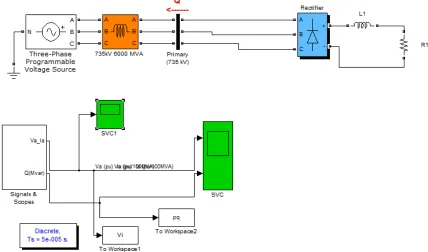
Static VAR Compensator (SVC)
Distribution STATIC COMPENSATOR (DSTATCOM)
ISSN (Print) : 2320 – 3765 ISSN (Online): 2278 – 8875
I
nternational
J
ournal of
A
dvanced
R
esearch in
E
lectrical,
E
lectronics and
I
nstrumentation
E
ngineering
(An ISO 3297: 2007 Certified Organization)
Vol. 4, Issue 9, September 2015
Surge arresters
But we used shunt passive filter, Thyristor Controlled Reactor (TCR) and Thyristor Switched Capacitor (TSC) with ac-dc converter supply system connected to R-L load are analysed through Matlab Control Toolbox to mitigate the harmonics at ac main.
III. STRUCTURE OF TCR&TSC
Thyristor-Controlled Reactor (TCR): A TCR is one of the most important building blocks of thyristor-based SVCs .Although it can be used alone ,it is more often employed in conjunction with fixed or thyristor-switched capacitors to provide rapid ,continuous control of reactive power over the entire selected lagging-to-leading range.Figure.1. shows the thyristor-controlled reactor (TCR) type of static compensation .Static compensators of the TCR type are characterized by having the following properties:
• Continuous control
• Maximum delay of one half cycles in the execution of a command from the regulator, as seen for a
single phase.
• Practically no transients
•
Generation of harmonicsA basic single phase TCR comprises an anti-parallel connected pair of thyristor valves,T1 and T2,in series with a linear air-core reactor. The anti parallel thyristor pair acts like a bidirectional switch ,with thyristor valve T1 conducting in positive half-cycles and thyristor T2 conducting in negative half-cycles of the supply voltage. The firing angle of the thyristors is measured from the zero crossing of the voltage appearing across its terminal. The controllable range of the TCR firing angle,extends from 90 to 180.The continuous sinusoidal current flow in the TCR but as range, the current reduces to zero for a firing angle of 180 and below 90,it introduce a dc current , disturbing the symmetrical operation of the two anti parallel valve branches.
Figure.1. Circuit diagram of TCR
The TCR is act like a variable susceptance. Variation of firing angle changes the susceptance and consequently the fundamental-current component which leads to a variation of reactive power absorbed by the reactor because the applied ac voltage is constant.
Thyristor Switch Control (TSC):It consists of capacitor in series with bidirectional thyristor switch.It is supplied from a ac voltage source.The analysis of the current transients after closing the switch brings two cases:
(i).The capacitor voltage is not equal to the supply voltage when the thyristors are fired. Immediately after closing the switch, a current of infinite magnitude flows and charges the capacitor to the supply voltage in an infinitely short time. The switch realized by the thyristor cannot withstand this stress and would fail.
ISSN (Print) : 2320 – 3765 ISSN (Online): 2278 – 8875
I
nternational
J
ournal of
A
dvanced
R
esearch in
E
lectrical,
E
lectronics and
I
nstrumentation
E
ngineering
(An ISO 3297: 2007 Certified Organization)
Vol. 4, Issue 9, September 2015
state values, the thyristor have an upper limit of that they can withstand during the firing process. Here is infinite, and the thyristor switch will again fail.
Figure.2. Circuit diagram of TSC
The thyristor-switched capacitor (TSC) type of static compensation.The shunt-capacitor bank is split up into small steps, by using bidirectional thyristor switches it can be made switched in and out individually. The single-phase branch, consists of capacitor C and the thyristor switch TY and a minor component, the reactor L, which is used to limit the rate of rise of the current through the thyristors and also to prevent resonance with the network. The capacitor is switched out through the suppression of the gate trigger pulses of the thyristors.
Figure.3. Single branch of TSC
The capacitor in the stand-by state loses its voltage as it is provided by the resistance R and it is immediately get ready for a new connection, even if it has not been completely discharged. Static compensators of the TSC type are characterized by having the following properties:
• Stepwise control
• Average delay of one half-cycle (maximum one cycle) in the execution of a command from the regulator, as seen for a single phase
• Very low inrush transients
• No generation of harmonics
• Low losses at low-compensator reactive-power output.
•
IV. PARAMETERS OF THE TEST SYSTEM
ISSN (Print) : 2320 – 3765 ISSN (Online): 2278 – 8875
I
nternational
J
ournal of
A
dvanced
R
esearch in
E
lectrical,
E
lectronics and
I
nstrumentation
E
ngineering
(An ISO 3297: 2007 Certified Organization)
Vol. 4, Issue 9, September 2015
Table 1: Parameter of The Test System
V. SIMULINK MODEL OF TEST SYSTEM
To demonstrate the performance of these passive filters feeding a three-phase converter with R-L load, these passive filters are modelled in MATLAB environment along with SIMULINK and power system block set toolboxes. Different components of these converters such as low pass filter with R-L load are simulated in MATLAB/SIMULINK.Figure.4. shows the MATLAB model of a passive series filter based six pulse ac-dc converters with R-L load. Depending on the harmonic spectrum of the supply current, the passive filters designed are low pass filter tuned for 5th order harmonic frequency. The subsystem named shunt filter consists of 5th harmonic frequency. Based on the design carried out the
filter component values are L=16mH, C=25µF, R=0.83Ω.
ISSN (Print) : 2320 – 3765 ISSN (Online): 2278 – 8875
I
nternational
J
ournal of
A
dvanced
R
esearch in
E
lectrical,
E
lectronics and
I
nstrumentation
E
ngineering
(An ISO 3297: 2007 Certified Organization)
Vol. 4, Issue 9, September 2015
The performance of passive filters with TCR and TSC feeding a three-phase converter with R-L load, these are modelled in MATLAB environment along with SIMULINK and power system block set toolboxes.
Figure.5. MATLAB based model of a six pulse ac-dc converter R-L load passive filter with TCR and TSC combination
VI. SIMULATION RESULTS
The configuration of passive shunt filter has been simulated and developed for six pulse ac-dc converter with R-L load. The simulated and test results of without passive shunt filter configurations and passive filter with TCR&TSC combination are presented here. The performance of a six pulse converter R-L load without passive shunt filter and passive filter with TCR&TSC is presented and discussed. It shows the waveforms of supply voltage Vs, voltage at point of common coupling (PCC) Vpcc, supply current is, load current il, filter current ish and the dc link voltage Vdc(V). It can be observed that the supply current wave form improves as the shunt filter is switched on. The passive filter has been designed such that the rms current drawn from the ac mains is less than the load current.
ISSN (Print) : 2320 – 3765 ISSN (Online): 2278 – 8875
I
nternational
J
ournal of
A
dvanced
R
esearch in
E
lectrical,
E
lectronics and
I
nstrumentation
E
ngineering
(An ISO 3297: 2007 Certified Organization)
Vol. 4, Issue 9, September 2015
Figure.6b. Waveform of Active and Reactive Power of Six Pulse ac-dc Converter Supply System Connected to R-L Load without Passive Filter
Figure.7a. Waveform of Current and Voltage of Six Pulse ac-dc Converter Supply System Connected to R-L Load with Passive Filter and Combination of TCR&TSC
Figure.7b. Waveform of Active and Reactive Power of Six Pulse ac-dc Converter Supply System Connected to R-L Load with Passive Filter and Combination of TCR&TSC
VII. CONCLUSION
Harmonic distortion in the waveform with SVC is much more than TCR&TSC. Hence TCR-TSC combination is better in SVC. Because harmonic are reduced by larger extent using TCR-TSC combination.
REFERENCES
[1] A. Hamadi, S. Rahmani, and K. Al-Haddad, “A hybrid passive filter configuration for VAR control and harmonic compensation,” IEEE Trans. Ind. Electron., vol. 57, no. 7, pp. 2904-2915, July 2010.
[2] A. Sode-Yome, N. Mithulananthan, “Comparison of shunt capacitor, svc and STATCOM in static voltage stability margin enhancement,” International journal of electrical engineering education, vol. 41, no. 2, pp. 158-171, 2004
[3] A. Johnson, R. Tucker, T. Tran, J. Paserba, D. Sullivan, C. Anderson, and D. Whitehead, “Static VAR compensation controlled via synchrophasors,”34th Annual Western Protective Relay Conference, Oct. 2007, pp. 1-7.
ISSN (Print) : 2320 – 3765 ISSN (Online): 2278 – 8875
I
nternational
J
ournal of
A
dvanced
R
esearch in
E
lectrical,
E
lectronics and
I
nstrumentation
E
ngineering
(An ISO 3297: 2007 Certified Organization)
Vol. 4, Issue 9, September 2015
[5] B.K. Bose, Modern power electronics and AC drives, Prentice Hall Of India, New Delhi, 2008.
[6] D.J. Hanson, M. L. Woodhouse, C. Horwill, D. R. Monkhouse, and M. M. Osborne, “STATCOM: a new era of reactive compensation,” Power Engineering Journal, pp. 151- 160, Jun. 2002.
[7] E. R. Ribeiro, and I. Barbi, “Harmonic voltage reduction using a series active filter under different load conditions,” IEEE Transactions on Power Electronics, vol. 21, no. 5, pp.
[8] J. P. Nelson, “A better understanding of harmonic distortion in the petrochemical industry,” Proc. IEEE PCIC, 2002, pp. 237-250.
[9] K. V. Kumar, G.Surendar, M. P. Selvan, “Performance comparison of shunt active filter and hybrid active filter,” NSC, pp. 71-76, Dec. 2008. [10] Kannan Karthik, and J.E.Quaicoe, “Voltage compensation and harmonic suppression using series active and shunt passive filters,” Electrical and Computer Engineering, Canadian Conference, vol. 1, 2000, p. 582-586.
[11] K. Kahle, “Static VAR compensation for the SPS electrical network,” CERN, pp.195- 201, Jan 2000. [12] Electrical Power System Quality Books by Roger C. Dugan / MARK F. McGranaghan