Simulation of a Bandstop Filter with Two
Open Stubs and Asymmetrical Double
Spurlines
S. Yang
Assistant professor, Department of EE and CS, Alabama A & M University, Huntsville, Alabama, USA
ABSTRACT: A compact microwave bandstop filter (BSF) with high rejection is proposed. This filter combines a conventional two open stubs BSF and asymmetrical double spurlines. Simulations show this BSF has a wider and a deeper stopband without increasing circuit size, compared with the conventional BSF. This BSF is used to suppress the first harmonics of a parallel coupled banpass filter (BPF). Simulations show deeper suppression compared with the application of a conventional BSF.
KEYWORDS: Asymmetrical Double Spurlines, Bandstop Filter, Harmonic Suppression.
I. INTRODUCTION
Microwave bandstop filters (BSFs) are being widely used in telecommunication systems. Various techniques have been developed to design and synthesis BSFs [1]. Conventionally, by cascading more open stubs onto a microstrip, a wider rejection bandwidth and a deeper rejection can be obtained. The side effects of this method are the high insertion loss in the passband and increased circuit size [2-3]. In this paper, a microstrip BSF with two open stubs and asymmetrical double spurlines is presented. By inserting asymmetrical double spurlines between the two open stubs, wider rejection bandwidth and deeper rejection can be achieved without increasing the overall circuit size. The proposed BSF is simulated and then is used to suppress the first harmonics of a BPF.
II. RELATED WORK
A conventional open stubs BSF can be formed by mounting two open stubs onto a microstrip. The length of the two stubs and the separation between the two stubs are a quarter of the wavelength at the midband frequency [2]. Spurline was proposed by Bates to generate bandstop filters (BPFs) [4]. A spurline is realized by etching an L-shaped slot on a microstrip. Asymmetrical double spurlines were proposed by Liu, Cao, and Shi to form a dual-bandgap BSF [5]. Double spurlines are formed by etching two spurlines at the two sides of a microstrip. Liu, Tong and Li have used asymmetrical double spurlines to suppress two harmonics of a microwave amplifier [6]. The proposed BSF is a combination of a conventional BSF and asymmetrical double spurlines.
III. FILTER LAYOUTS AND SIMULATION RESULTS
Fig. 1 Layout of a conventional open stubs BSF
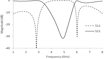
This conventional BSF is simulated on Sonnet Suite 14.52. The mesh size is chosen as 0.01 mm by 0.01 mm. Sonnet Suite is a 3D planar EM software based on Method of Moments. Simulation results on return loss S11 and insertion loss S21are shown in Fig. 2. The midband frequency is at 4.9 GHz. The deepest rejection is about 32 dB.
Fig. 2 Simulation results of the conventional open stubs BSF
Asymmetrical double spurlines on the substrate mentioned above are shown in Fig. 3. The width of the microstrip is 1.2 mm. The dimensions of the short spurline are width 0.3 mm, length 5.66 mm and gap 0.1 mm. The dimensions of the long spurline are width 0.2 mm, length 6.86 mm and gap 0.1 mm. The short spurline is wider than the long spurline.
Fig. 3 Layout of an asymmetrical double spurlines
Fig. 4 Simulation results of the asymmetrical double spurlines
The proposed BSF is a combination of the conventional open stubs BSF and the asymmetrical double spurlines. The asymmetrical double spurelines are inserted between the two open stubs of the conventional BSF. Layout of this BSF is shown in Fig. 5. All the dimensions in this layout have been mentioned early.
Fig. 5 Layout of the proposed BSF
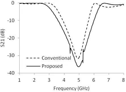
The proposed BSF is simulated on Sonnet Suite. The insertion losses of the proposed BSF and the conventional BSF are shown together in Fig. 6 for comparison. The asymmetrical double spurlines generate two attenuation poles at the two sides of the midband frequency. The proposed BSF has wider rejection bandwidth and deeper rejection capability. Its 20 dB rejection band is from 4.18 to 5.60 GHz. Its 30 dB rejection band is from 4.62 to 5.26 GHz. The deepest rejection reaches -36 dB.
IV. FIRST HARMONIC SUPPRESSION OF A BANDPASS FILTER
The proposed BSF is connected to the output of a third order parallel coupled BPF [7] to suppress its first harmonics. The layout is shown in Fig. 7. This kind of BPF consists of a bunch of parallel line pairs. Microwave signals are coupled between these paired lines. The length of these line pairs is a quarter of the wavelength at the midband frequency. The design of this filter is through the calculation of even-mode and odd-mode characteristic impedances of coupled line pairs and the computation of physical dimensions of these line pairs [7]. This BPF has a midband frequency of 2.45 GHz and a bandwidth of 200 MHz.
Fig. 7 Layout of a BPF with proposed BSF for harmonic suppression
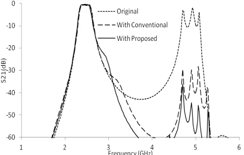
This parallel coupled BPF has a passband around 2.45 GHz and a first harmonics around 4.9 GHz. The whole filter is simulated again on Sonnet Suite. The simulation results are shown in Fig. 8. The first harmonics around 4.9 GHz is highly suppressed for more than 33 dB. At the same time, the insertion loss in the passband does not get much disturbance. For comparison, the insertion losses of the original BPF, and the whole filter with conventional and the proposed BSFs are shown together. The proposed BSF has better performance than the conventional BSF on the first harmonic suppression.
Fig. 8 Simulated insertion loss of the BPF with and without BSFs
V. CONCLUSIONS
A pair of asymmetrical double spurlines is inserted between the two open stubs of a conventional BSF to form a novel BSF. The proposed BSF is simulated on Sonnet Suite software. Simulation results show the proposed BSF has a wider rejection bandwidth and deeper rejections compared with the conventional BSF. This proposed BSF is also used to suppress the first harmonics of a parallel coupled BPF. Simulation results show the first harmonics is suppressed more compared with the application of a conventional BSF.
ACKNOWLEDGMENT
REFERENCES
1. Hong, J. S., Microstrip Filters for RF/Microwave Applications, John Wiley and Sons Inc., 2011.
2. Tu, W. H., and Chang, K., “Compact microstrip bandstop filter using open stub and spurline”, IEEE Microwave and Wireless Components Letters vol.15, No. 4, pp. 268-270, 2005.
3. Angkawisittpan, N., “Miniaturization of bandstop filter using double spurlines and double stubs”, Electrical Review, R. 88 NR11a, pp. 178 – 181, 2012.
4. Bates, R. N., “Design of microstrip spur-line band-stop filters”, Microwave, Optics, and Acoustics, Volume 1, No. 6, 1977.
5. Liu, H. W, Sun, L, and Shi, Z., “Dual-bandgap characteristics of spurline filters and its circuit modeling”, Microwave and Optical Tech. Lettl, Vol. 49, no. 11, pp.2805-2807, 2007.
6. Liu, H. W, Tong, F., and Li, X. H., “Asymmetrical spurline resonator design and its application to power amplifier”, IEEE MTT-S International Shop Series on Art of Miniturizing RF and Microwave Passive Components, Chengdu, China, December, 2008