ISSN (Print) : 2320 – 3765 ISSN (Online): 2278 – 8875
I
nternational
J
ournal of
A
dvanced
R
esearch in
E
lectrical,
E
lectronics and
I
nstrumentation
E
ngineering
(An ISO 3297: 2007 Certified Organization)
Vol. 5, Issue 4, April 2016
A Study on DC Motor Operations and Speed
Control Using Microcontroller
Anjaly Divakar1, Jibin Joseph2, Jinu T George3, Nandakumar N Prabhu4, Absal Nabi5
B.Tech Student, Dept. of EEE, Ilahia College of Engineering and Technology, Ernakulam, Kerala, India1
B.Tech Student, Dept. of EEE, Ilahia College of Engineering and Technology, Ernakulam, Kerala, India2
B.Tech Student, Dept. of EEE, Ilahia College of Engineering and Technology, Ernakulam, Kerala, India3
B.Tech Student, Dept. of EEE, Ilahia College of Engineering and Technology, Ernakulam, Kerala, India4
HOD, Dept. of EEE, Ilahia College of Engineering and Technology, Ernakulam, Kerala, India5
ABSTRACT: The project is proposed to develop a four quadrant speed control system for a DC motor with Pulse width modulation (PWM). The motor is operated in four quadrants i.e. clockwise, anti clock-wise, forward braking and reverse braking. Four quadrant operations are suited for industrial applications. DC motor can rotate in clockwise, anti-clockwise directions. Also we can apply braking for instantaneous stop in both the directions. In case of urgent operation in industrial field the motor may needs to be stopped immediately. In such a case these systems is very useful for forward braking and reverse braking. As the reverse voltage is used for running DC motor the braking in both directions is possible for a small period. PWM pulses generated by microcontroller also control the speed of the motor Microcontroller used in this project is from the 8051 family. A motor driver IC is provided here for motor speed control also seven push buttons are interfaced with microcontroller for giving input signal as well as to operate the motor. This project features the speed control by the push button operation. To operate high capacity DC motors this project can be enhanced by using high power electronic devices.
KEYWORDS: Four quadrant operation, Pulse width modulation, Hardware model and Softwares, Working
I.INTRODUCTION
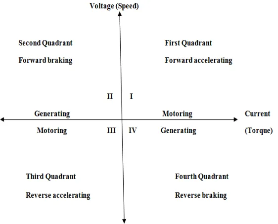
Fig .1 Four Quadrant operations
Fig 1 shows the four possible modes or quadrants of operation [3] using a DC Motor. The four operations named as forward motoring, forward braking, reverse motoring, and reverse braking in the 1st, 2nd, 3rd and 4th quadrants respectively.
II.PULSE WIDTH MODULATION
Pulse-width modulation (PWM) [2] is a commonly used technique for controlling power to an electrical device, made practical by modern electronic power switches. The average value of voltage (and current) fed to the load is controlled by turning the switch between supply and load on and off at a fast pace. The longer the switch is on compared to the off periods, the higher the power supplied to the load is. The term duty cycle describes the proportion of on time to the regular interval or period of time; a low duty cycle corresponds to low power, because the power is off for most of the time. Duty cycle is expressed in percent, 100% being fully on. The main advantage of PWM is that power loss in the switching devices is very low. When a switch is off there is practically no current, and when it is on, there is almost no voltage drop across the switch. Power loss, being the product of voltage and current, is thus in both cases close to zero. PWM works also well with digital controls, which, because of their on/off nature, can easily set the needed duty cycle. PWM has also been used in certain communication systems where its duty cycle has been used to convey information over a communications channel. The duty cycle determines the speed of the motor. The desired speed can be obtained by changing the duty cycle. The PWM in microcontroller is used to control the duty cycle of DC motor. The PWM pulses generated from the microcontroller are viewed for various duty cycles in the simulation done in proteous software.
III.BLOCK DIAGRAM
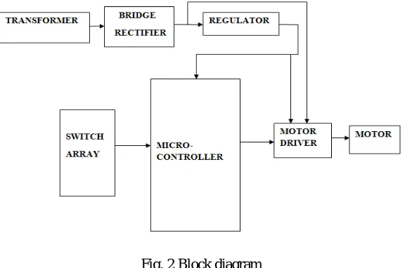
Fig 2 shows the main block diagram of the project. It includes a Transformer, Bridge rectifier, Voltage regulator, Switch array, Microcontroller, Motor driver IC and DC motor.
TRANSFORMER: The power supply for the circuit is given through step down transformer, which converts from 230V to 12V.
ISSN (Print) : 2320 – 3765 ISSN (Online): 2278 – 8875
I
nternational
J
ournal of
A
dvanced
R
esearch in
E
lectrical,
E
lectronics and
I
nstrumentation
E
ngineering
(An ISO 3297: 2007 Certified Organization)
Vol. 5, Issue 4, April 2016
REGULATOR: The output of the bridge rectifier is connected to the regulator [8] which regulates the 12 volt unregulated dc to regulated 5V supply.
SWITCH ARRAY: Switch array consist of 7 push button switches. Each switch is assigned specific functions, accordingly control pulses is given to motor driver IC for controlling Motor.
Fig. 2 Block diagram
MICROCONTROLLER: The microcontroller [5] used is AT89C51.It is 40 pin ic which operates using 5V dc.
MOTOR DRIVER IC: The IC used is L293D.It is a dual H-bridge motor driver integrated circuit (IC).It works based on the signal from the microcontroller.
MOTOR: The motor used is 12V DC motor, which performs all the 4 quadrant operations.
IV.WORKING
The circuit uses standard power supply comprising of a step down transformer from 230V to 12V and the four diodes forming a bridge rectifier that delivers pulsating dc which is unregulated is regulated to constant 5V dc. The output of the power supply which is 5V is connected to the microcontroller. Here seven switches are interfaced to MC to control the speed of motor in four quadrants [6]. When start switch is pressed the motor starts rotating in full speed being driven by a motor driver IC L293D [7] that receives control signal continuously from the MC. When clockwise switch is pressed the motor rotates in forward direction as per the logic provided by the program from the MC to the motor driver IC. While forward brake is pressed a reverse voltage is applied to the motor by the motor driver IC by sensing reverse logic sent by the MC for a short time period due to which instantaneous brake situation is applied to the motor. Similarly when motor is rotating in anti-clockwise direction by appropriate logic from the MC to the motor driver IC and reverse brake switch is pressed the MC delivers a logic to the motor driver IC that develops for very small time a reverse voltage across the running motor due to which instantaneous brake situation happens to the motor.
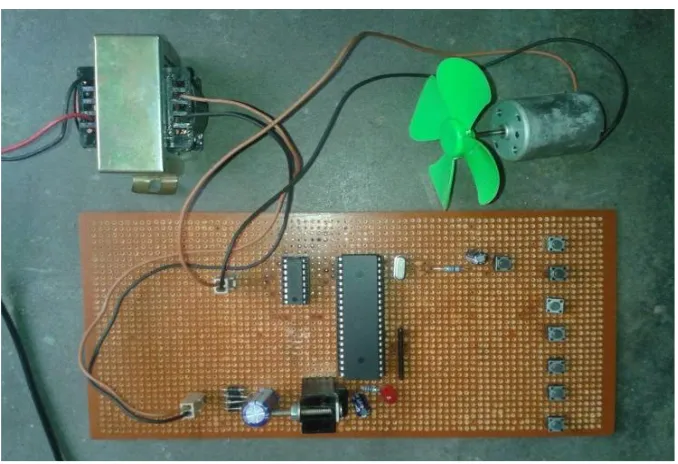
Fig. 3 Hardware model
Fig 2 shows the hardware model of the project. It includes a Transformer, Bridge rectifier, Voltage regulator, Switch array, Microcontroller, Motor driver IC and DC motor. When the switches are pressed and released the respective operations are performed by the DC motor as assigned. Start, stop, Forward motoring, Reverse motoring, Forward braking, Reverse braking, PWM speed control and Stop are the functions assigned to 1st,2nd,3rd,4th,5th,6th and 7th pushbuttons respectively.
V. ALGORITHEM 1. Start
2. Initialize variables and functions 3. Check the inputs from the push bottom Start=P1*0
Clock=P1*1 Anti_clock=P1*2 F_break=P1*3
4. If start=0; EN1=1, IN1=1, IN2=0.Motor is on.
5. If clock=0; EN1=1, IN1=1, IN2=0.Motor runs in clockwise direction. 6. If a_clock=0; EN1=1, IN1=0, IN2=1. Motor runs in anti-clockwise direction. 7. If f_break=0; Stops motor immediately in the forward direction.
8. If a_break=0; Stops motor immediately in the reverse direction. 9. If stop=0; Stops motor.
10. Stop.
VI. SOFTWARE USED
Kiel: Support every level of software developer from the professional applications engineer to student in learning about embedded software development. When starting a new project, simply select the microcontroller and µvision IDE sets all compiler, assembler, linker, and memory options.
ISSN (Print) : 2320 – 3765 ISSN (Online): 2278 – 8875
I
nternational
J
ournal of
A
dvanced
R
esearch in
E
lectrical,
E
lectronics and
I
nstrumentation
E
ngineering
(An ISO 3297: 2007 Certified Organization)
Vol. 5, Issue 4, April 2016
VII.RESULT
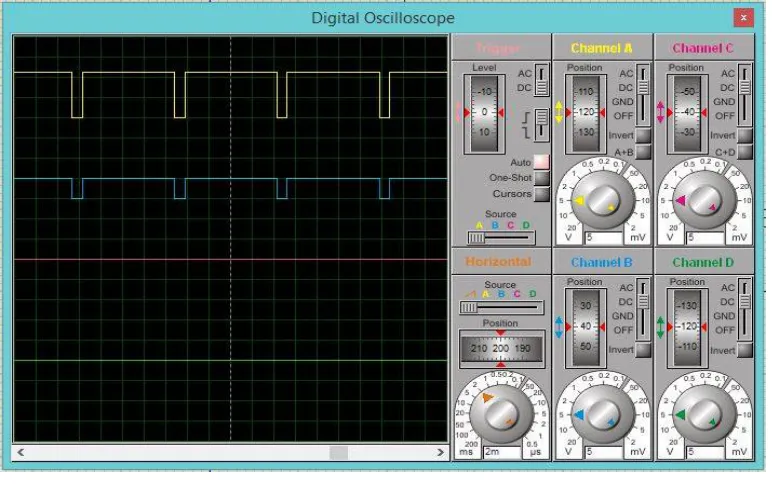
Fig. 4 PWM output waveform
Fig 4 shows the simulated PWM output waveform obtained in Proteus software. It indicates 10% duty cycle. For each further pressing of PWM button the speed of the motor decreases by 10%.Corresponding change in duty cycle can be observed in the above simulation diagram.
VIII.CONCLUSION
The proposed research work will make a prototype hardware model where the PWM technique has been used to control the speed of dc motor. By variation in duty cycle, applied voltage varies therefore speed of dc motor can be controlled.PWM duty cycle control techniques enable greater efficiency of the DC motor.
IX.ACKNOWLEDGEMENT
First and foremost I take this opportunity to express my deepest sense of gratitude to my guide Mr. Absal Nabi for his able guidance during my project work. This project would not have been possible without his help and the valuable time that he has given me at his busy schedule. I would also like to extend my gratitude to my friends and senior students of this department who have always encouraged and supported me in doing my work. Last but not the least I would like to thank all the staff members of Department of Electrical Engineering who have been very cooperative with us.
REFERENCES
[1] H. Chen; J. Zhang,”Study of embedded system experimental platform”Consumer Electronics, Communications and Networks (CECNet), 2012 2nd International Conference on 2012 Pages: 1317 – 1320,2012.
[2] J. Holtz, “Pulsewidth modulation-a survey,” IEEE Trans. on Industry Electronics, Vol. 39, No. 5, 1992
[3] Devika R. Yengalwar, Samiksha S. Zade, Dinesh L. Mute “Four Quadrant Speed Control Of Dc Motor Using Chopper” International Journal Of Engineering Sciences & Research Technology,vol. 4 issue 2, ISSN: 2277-9655,pp 401-406,February, 2015
[4] M. K. Yoong, Y. H. Gan, G. D. Gan, C. K. Leong, Z. Y. Phuan, B.K. Cheah, and K. W. Chew, “Studies of regenerative braking in elec-tric vehicle,” in.Proc. IEEE Conf. Sustainable Utilization DevelopmentEng. Technol.,Malaysia, , pp. 40–45, Nov. 2010.
[5] Y. S. E. Ali, S. B. M. Noor, S. M. Uashi and M. K Hassan” MicrocontrollerPerformance for DC Motor Speed Control” O-7803-8208,2003 IEEE.