Harmonic Mitigation Techniques: A Review
Jyotsana Kaiwart1, Uma P. Bala Raju2M.Tech Scholar, Department of EE, Bhilai Institute of Technology, Durg, India 1 Assistant Professor, Department of EE, Bhilai Institute of Technology, Durg, India 2
ABSTRACT: This paper discusses various harmonic mitigation techniques, which are available to solve harmonic
problems in power system. Harmonic problems cause poor power transfer as ultimate effect and, hence, reduction in low efficiency of system. This paper includes the advantages and disadvantages of each technique. This includes the normal circuit connections and expected performance of each technique too. In addition to explaining the theory of operation, useful diagrams and charts are provided, so that the reader can directly apply this information for analysis of their own power system circumstances.
KEYWORDS: Isolation transformers, K-factor Transformers, Tuned Harmonic Filters, 12 & 18 pulse rectifiers, Phase
shifting Transformers, Active harmonic filters, Low pass harmonic filters
I.INTRODUCTION
This paper discusses various harmonic mitigation techniques, which are available to solve harmonic problems in power system. This explains the operations of all the harmonic mitigation techniques listed below:
1. Line reactor
2. Isolation transformer
3. K-factor transformer
4. Tuned harmonic filter
5. IGBT based fast switched harmonic filter
6. Low pass harmonic filter
7. 12 & 18 pulse rectifier
8. Phase shifting transformer
9. Active harmonic filters
The methods, listed above, are explained with their main features including their advantages and disadvantages. The choice of suitable method of harmonic mitigation is dependent on the user’s objective and severity of harmonics.
II.METHODS
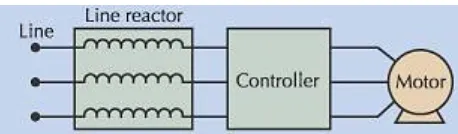
A. LINE REACTOR
The line reactor is the simplest means of attenuating harmonics. It is connected in series with an individual non-linear load, e.g. adjustable speed drives, to insert series inductive reactance in circuit. This is not only attenuate harmonics but also absorb voltage transients, which can cause a voltage source adjustable speed drive to trip on an over-voltage. The magnitude of harmonic distortion and actual spectrum of harmonics depend on the effective impedance of this reactor.
Advantages: 1. It cost low.
2. It can provide moderate but significant reduction in voltage and current harmonics. 3. It is available in various values of percent impedances.
Disadvantages:
1. It causes a voltage drop. 2. It increases system losses.
3. The normal impedance value of line reactor don’t achieve current distortion levels much below 35% THD-I.
Line reactor is of two types:
1. AC line reactor: The impedance rating of this line reactor indicates the per unit impedance to its rated full load current.
2. DC line reactor: It is series inductance installed on the dc link of VFD. DC choke provides a greater harmonics reduction for the 5th and 7th harmonics.
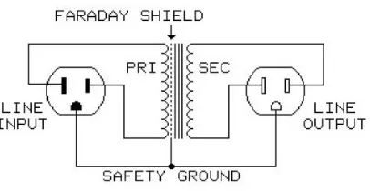
B. ISOLATION TRANSFORMER
Input circuit reactance is a major factor to determine the magnitude of harmonics, which will be present and flowing to an individual load. Hence, isolation transformer can be used effectively to reduce harmonic distortion. Its leakage inductance can offer appropriate values of circuit impedance to attenuate harmonics. It can also be supplied with an electrostatic shield between the primary and secondary windings. Due to capacitive coupling between each winding and the shield, a low impedance path is created to attenuate noise, transients and zero sequence currents. The shield helps to mitigate the common mode disturbances to their originating side of transformer.
Figure 2: Isolation Transformer
Advantages:
1. It can reduce both common mode and normal mode disturbances as well as provide circuit isolation.
Disadvantages:
1. It can achieve effective harmonic attenuation with only proper physical size. It should be sized as close as possible to the rated load current and has their impedance based on load current and voltage.
2. It causes more circuit losses and cost as compared to line reactor.
C. K-FACTOR TRANSFORMER
multiple insulated conductors that are transposed to reduce the skin effect. The magnetic core is designed with a lower flux density. The K-factor is a function of two variables i.e. magnitude of harmonic current and harmonic order.
Generally the K-factor Transformers are
used:-Value of K-Factor Application
1 Standard transformer, Standard lighting, Motors
4 Induction heater, SCR, AC Drives
9 DC Drives
13 School pulse lighting, Hospital
20 Data processing computer, computer rooms
Advantages:
1. The K-factor requirement of mixed load (linear and non-linear loads) is lower than that of only non-linear load.
2. The K-factor transformer can handle the heat associated with eddy current losses, which are K times greater
than a non K-factor transformer.
Disadvantages:
1. It costs higher than previous for each horse power.
D. TUNED HARMONIC FILTER
It is a device with basic elements as inductive and capacitive reactance. These reactive elements are connected in series to form a tuned LC circuit. It is connected as a shunt device in power system. It is a resonant circuit at the tuning frequency, at which it offer very low impedance. This makes it to become the source of the tuned frequency harmonic energy demanded by the loads. It means that, at tuning frequency, the filter offer very low resistances and the greater amount of harmonic current flows through it. The total harmonic current distortion decreases.
Figure 3: Tuned harmonic filter
A tuned filter can be designed in different ways:
1. Fixed type (for Low and Constant power factor and harmonic with constant magnitude)
2. Automatic type (for fluctuating power factor and magnitude of harmonics)
3. Hybrid type (consists of Fixed and Automatic type)
A tuned filter is normally used when the total harmonic current distortion is greater than 20% THD-I.
Advantages:
1. It improves the displacement power factor due to capacitive behaviour at low frequencies.
Disadvantages:
1. The capacitance of tuned filter may cause a resonance problem if initial THD-I is less than 20%. 2. It doesn’t eliminate the tuned harmonics, but it only mitigates it.
E. IGBT BASED FAST SWITCHED HARMONIC FILTERS
The changes in Reactive power over time can be achieved by an automatic filter. But automatic filter will not respond quickly enough to meet requirement of reactive power. Also, acceptable power factor and harmonic distortion level are to be maintained. That’s why, fast switching harmonic filter with IGBT (Isolated Gate Bipolar Transistors) is used. It can be switched without discharging the capacitor at switching rates up to 60 times per second.
Advantage:
1. This filter has the capability to switch without transient and to respond in real time, to dynamically changing load conditions.
2. The total harmonic current distortion can be achieved is from 3% to 12%.
F. LOW PASS HARMONIC FILTERS
It includes one or more series elements with a set of tuned elements. The series elements increase the input circuit effective impedance to reduce overall harmonic and to de-tune the shunt element relative to supply and load ends. It has gained popularity due to ability to attenuate all harmonic frequencies and achieve low level of residual harmonic distortion.
Advantages:
1. It costs low comparatively.
2. It has low residual harmonics.
3. Its result is predictable and guarantee-able. 4. It doesn’t require any analysis or harmonic studies.
Disadvantages:
1. It must connect in series with the load.
2. It can only be used with non linear loads, because it can cause increased heating effect and lower life expectancy for linear loads.
3. It experiences low leading power factor at light loads due to occurrence of voltage boosting because of presence of shunt capacitor and reactor. All above results in additional losses.
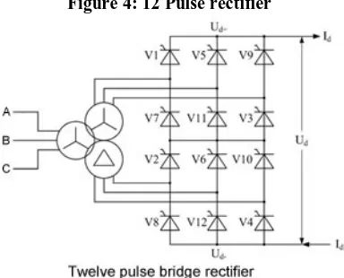
G. 12 & 18 PULSE RECTIFIER
It involves a special type of rectifier and transformer configuration. In case of 12 pulse and 18 pulse system, the transformers have two and three, respectively, separate secondary windings. The degrees of phase shift between each secondary are 360 divided by the number of rectifier pulses.
Advantages:
1. 12-pulse rectifier system can achieve input current distortion levels from 10% to 20 % THD-I. 18-pulse rectifier system can achieve input current distortion levels from 5 % to 10 % THD-I at full load conditions.
Disadvantages:
1. THD-I increases with decrease in load.
Figure 4: 12 Pulse rectifier
H. PHASE SHIFTING TRANSFORMER
This transformer operates as a quasi 12-pulse method. Two sets of non-linear loads are fed by two phases shifted transformer winding. The 5th and 7th harmonic in primary side of transformer is cancelled to balance the current in each of secondary winding. The attenuation of higher order harmonics is based on the effective percent impedance of transformer.
Figure 5: 12 Phase Shifting Transformer
Advantages:
1. 5th and 7th harmonic are cancelled approximately for equal loading condition.
I. ACTIVE FILTER
These filtering techniques can be applied either as a standalone harmonics filter or by incorporating the technology into the rectifier stage of a drive, UPS or other power electronics equipment. It will monitor the load current. It filters out the fundamental frequency current and analyse the frequency and magnitude content of the remaining current. Then, it injects the appropriate inverse currents to cancel the individual harmonics. It uses fast switching transistors (IGBT).
Advantages:
1. It cancels harmonics up to about 50th harmonics.
Disadvantages:
1. It may perform low due to high level of pre-existing voltage distortion. 2. It requires more maintenance due to use of power electronic circuitry. 3. It costs high and also losses are greater than passive filters.
III. COMPARISON
This table shows the approximate costs (in $) and typical performance of various solutions for three phase harmonic mitigation. Harmonic mitigation techniques 20 Hp price 100 Hp price 400 Hp price THD-I Non-linear loads (%) THD-I
Mixed ( 50-50 ) loads (%)
Reactor
(5%)
520 1100 3800 35 17.5
Isolation Transformer
2650 6340 18000 35 17.5
K-factor (13) Transformer
5300 11000 48000 35 17.5
Tuned Filter 2800 3900 7000 15-20 3-12
Low Pass Filter 2400 5600 13000 8-15 n/a
Active Filter n/a 27000 65000 5 5
IV.CONCLUSION
As the methods of harmonic mitigation are explained above, it concludes that there is no single product that is best solution for harmonics. The best economical and technical solution for this problem is based on objective of user, severity of harmonics, cost and benefits associated with various technologies used at that place. Hence, hybrid approach to mitigate harmonic is the best suitable method. It also offers the best opportunity to gain internal power system benefits.
REFERENCES
[1] Ewald F.Fuchs, Mohammad A. S. Masoum, “Power Quality in Power Systems and Electrical Machines”, 2008, Elaevier Inc. [2] Francisco C. De. La. Rosa, “Harmonics and Power System”, 2006, Taylor and Francis Group, LLC, pp 175-176.
[3] Gonzalo Sandoval, John Houdek, “A Review of Harmonic Mitigation Techniques”, Allied Industrial Marketing USA, 2005 [4] Jeel Contractor, P .N. Kapil, Bhavin Shah,”Harmonic Mitigation for Power Quality Improvement”, IJRET, vol. 04, May 2015.
[5] Sanjay A. Deokar Sanjay A. Deokar, Dr. Laxman M. Waghmare, “Impact of Power System Harmonics on Insulation Failure of Distribution Transformer and its Remedial Measures”, © 2011 IEEE
[6] M. El-Habrouk, M. K. Darwish and P. Mehta, “Active Power filters: A review”, IEE Proc.-Electrical Power Application, Vol. 147, No. 5, September 2000.
[7] Hirofumi Akagi, “Trends in Active Power Line Conditioners”, IEEE transaction on Power Electronics, vol. 9, no. 3, May 1994
[9] Bhim Singh, Kamal Al-Haddad and Ambrish Chandra, “A Review of Active Filters for Power Quality Improvement”, IEEE TRANSACTIONS ON INDUSTRIAL ELECTRONICS, Vol. 46, No. 5, Oct 1999.
[10] N.R Jayasinghe, J.R Lucas and K.B.I.M. Perera, “Power System Harmonic Effects on Distribution Transformers and New Design Considerations for K Factor Transformers”, IEE Sri Lanka Annual Sessions, Sep 2003.
[11] Zainal Salam, Tan Perng Cheng and Awang Jusoh, “Harmonics Mitigation Using Active Power Filter: A Technological Review”, Faculty of Electrical Engineering University Teknologi Malaysia, Vol. 8, No. 2, 2006.
[12] Hanju Cha and Trung-Kien Vu, “Comparative Analysis of Low-pass Output Filter for Single-phase Grid-connected Photovoltaic Inverter”, IEEE ©2010.
BIOGRAPHY
Jyotsana Kaiwart received B.E. (Electrical Engineering) degree from Chhattisgarh Swami Vivekananda Technical University, Bhilai, Chhattisgarh, India in 2014. She is presently pursuing M.Tech. (Industrial Drives and Control) from Bhilai Institute of Technology, Durg, India. Her current research interest includes different methods to mitigate harmonic efficiently.