MICROSTRIP BAND-REJECT FILTER BASED ON INTER-DIGITAL CAPACITANCE LOADED LOOP RES-ONATORS
Y. Peng and W. X. Zhang
State Key Lab of Millimeter Waves Southeast University
Nanjing 210096, China
Abstract—In this paper, the inter-digital capacitance loaded loop resonators (IDCLLRs) are proposed to design microstrip band-reject filters. The analyzed structures are based on the coupling of IDCLLRs to a conventional 50 Ω microstrip transmission line. We have firstly studied the frequency response of one-stage IDCLLR-loaded microstrip transmission line. The main fratures of the IDCLLRs are small dimensions (much smaller than the wavelength at resonance) and more structural parameters (provide flexibility in design); Then a 6-stage IDCLLR-based microstip band-reject filter was designed and fabricated, it performs relative rejection bandwidth of 8.1% and rejection level of 23 dB. This stop-band is resulted from presence of the artificial medium with negative effective permeability (μeff <0). In addition, it is easy to control the rejection bandwidth by only employing different length of inter-digital fingers (for multiple tuning). A 9-stage band-reject filter with multiple tuned IDCLLRs has been fabricated and tested, its relative rejection bandwidth is extended to 11.5%. Simulated and measured results are presented.
1. INTRODUCTION
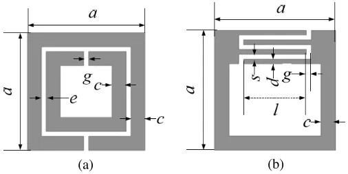
Recently, a novel family of printed microwave pass or band-reject filter has been designed based on the structure of sub-wavelength resonators, started from split ring resonators (SRRs). SRR originally proposed by Pendry consists of a pair of concentric metallic rings with a split etched in opposite sides (Fig. 1(a)) [1]. It has been demonstrated [2] that SRR behaves asLC resonator and can be excited
by external time-varying magnetic field with an appreciable component in its axial direction. The resonant frequency of SRR is given by
f0 = (LsCs)−1/2/2π, where Ls and Cs are equivalent inductance and
equivalent capacitance of SRR respectively. Csis the series capacitance of the left- and right-halves of SRR. Ls is the inductance of the ring with approximately average perimeter and width c [3]. The main feature of SRRs are that their size can be made much smaller than its resonant wavelength, thus the periodically arranged SRRs form an equivalent continuous medium with effective permeability μeff and permittivity εeff [3]. When a guided wave propagates inside such medium, the effective permeability takes positive/negative values in a narrow band below/above the resonance, and takes extreme values in the vicinity of f0. As a result, the propagation is prohibited, the
typical stop-band extends not only above f0 (μeff < 0), but also in a
narrow band below it. These stop-band performances can be applied to planar transmission structure to design band-reject filters. It has been shown that SRR-loaded microstrip line [4–6] and coplanar waveguide (CPW) [7, 8] behave as compact, highQ, band-reject filters with deep stopband in the vicinity of their resonant frequencies.
These characteristics of SRR had been extended to the other sub-wavelength resonators derived from the basic geometry of the SRR, for example, broadside coupled SRR (BC-SRR) [2, 9], spiral resonator (SR) [3], capacitance loaded loop resonator (CLLR) [10, 11],
S-ring resonator [12] and complementary split ring resonator (CSRR) [2, 5, 6, 13], etc. But SRRs have less structural parameters. Both Ls and Cs are determined mainly by the dimensions of SRR, but less by its geometry, so it is not sure to obtain desired resonant frequency for a SRR with given dimensions. The other kinds of
sub-(a) (b)
wavelength resonator mentioned above meet the same quandary. In order to hurdle this obstacle, the inter-digital capacitance loaded loop resonators (IDCLLRs) are proposed to construct the band-reject filters in this paper.
The geometry of an IDCLLR is described in Fig. 1(b). Obviously, more structural parameters are provided by the inter-digital structure. A special case of IDCLLR [14] has been used in designing a compact waveguide; In this work, a detail research for frequency response of IDCLLR is performed by both simulation and experiment. A band-reject filter is obtained by a 50 Ω microstip line coupling with two arrays of IDCLLRs. A 6-stage IDCLLR-based band-reject filter is fabricated and measured. The rejection bandwidth of the filter can be controlled by employing multiple resonators with slightly different resonant frequencies. The resonant frequencies of IDCLLRs can be tuned easily by only changing inter-digital length l. A 9-stage IDCLLR-based reject-band filter with multiple tuning has been designed and fabricated. The simulated and measured results are presented below for comparison.
2. INTER-DIGITAL CAPACITANCE LOADED LOOP RESONATOR (IDCLLR)
Just like SRRs, the IDCLLRs can be excited by an external magnetic field with polarization along its axis. At resonance, the time-varying magnetic field induces current along the ring, and continues with displacement current throughout the inter-digital capacitance. In general, the inter-digital structure with same width of finger and gap (i.e., d =s) corresponds to a maximum capacitance [15]. The quasi-static resonant frequency of IDCLLR is formulated asω0 = 1/
√ L0C0,
where L0 is equivalent inductance of IDCLLR, C0 is the quasi-static
capacitance of the inter-digital capacitor calculated approximately by using [16]
C0(PF) =
εe10−3K(k)
18πK(k) (N −1)l (1) where εe is effective permittivity in microstrip line with strip-width of d, N is the number of fingers, l is the length of each finger;
K(k) and K(k) are complete elliptic function of the first kind and its complementary function, their modulus is k = tan2[dπ/4(d+s)]. Obviously, the effective capacitance of IDCLLR depends on so many parameters, resulting in more freedom in designing.
(a)
(b)
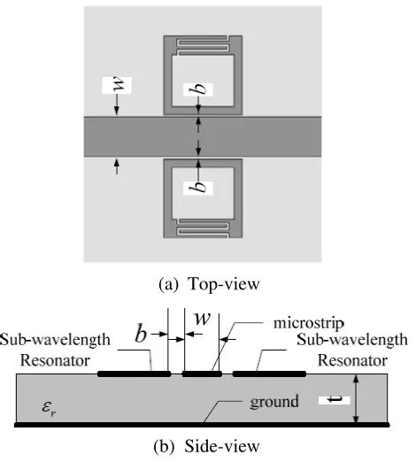
Top-view
Side-view
Figure 2. Geometry of IDCLLR-based microstrip one stage band-reject filter.
of the designed filter prototype is shown in Fig. 2. A 50 Ω microstrip line with strip-width of w = 3.05 mm and coupled by two IDCLLRs with spacing of b = 0.2 mm is etched on a Arlon diclad 880 substrate (εr = 2.2, t = 1 mm). The sizes in the IDCLLR are a = 6 mm,
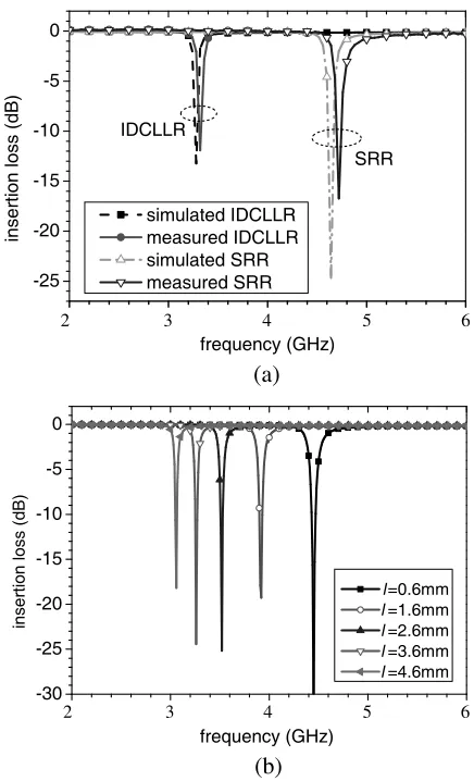
c = 0.6 mm, g = d = s = 0.2 mm, l = 3.6 mm, and the number of fingers is N = 4. This filter prototype has been simulated using software HFSS, and measured using Aglient PNA E8363B series vector network analyzer. The results of S21 frequency responses described in
Fig. 3(a) show the presence of a narrow notch and compare to that of SRR-based filter prototype with sizes of a = 6 mm, c = 0.6 mm,
g = e = 0.2 mm (see Fig. 1(a)). The resonant frequency of IDCLLR is identified by the transmission notch with insertion loss of−12 dB in stop-band, and rejection bandwidth (for−10 dB) of 13 MHz or relative bandwidth 0.39%.
-25 -20 -15 -10 -5 0
insertion loss (dB)
frequency (GHz) simulated IDCLLR measured IDCLLR simulated SRR measured SRR IDCLLR
SRR
2 3 4 5 6
(a)
-30 -25 -20 -15 -10 -5 0
insertion loss (dB)
l=0.6mm
l=1.6mm
l=2.6mm
l=3.6mm
l=4.6mm
2 3 4 5 6
frequency (GHz) (b)
Figure 3. (a) Simulated & measured insertion loss for IDCLLR-based and SRR-based filters. (b) Simulated insertion loss for IDCLLR-based filter with different finger length. ∗All the cells occupy the same area.
to improve the properties of stopband of IDCLLR-baseded filter, it is necessary to increase the number of IDCLLRs stages. A IDCLLR-based multistage filter will be introduced in next section.
Moreover, the resonant frequency of IDCLLR can be adjusted easily by changing parameters of the inter-digital structure. For convenience, we only change the length of finger l and keep s, d, and g (see Fig. 1(b)). From (1), we can expect that the resonant frequency of the structure will be shifted down as increasing the finger length. Fig. 3(b) shows the simulated S21 frequency responses of the
structure with same area but varied l = 0.6 mm, 1.6 mm, 2.6 mm, 3.6 mm, 4.6 mm, respectively. Which result in resonant frequency shift-down within a larger dynamic range from 4.45 GHz (for l = 0.6 mm) to 3.08 GHz (for l = 4.6 mm), corresponding to a reduction factor of 1.4 times.
(a)
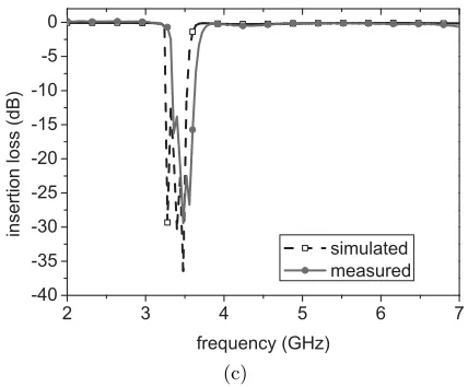
(c)
Figure 4. A 6-stage IDCLLR-based band-reject filter. (a) Prototype for testing. (b) Simulated and measured return-loss. (c) Simulated and measured insertion-loss.
3. IDCLLR-BASED BAND-REJECT FILTER DESIGN
The cascade of electrically small IDCLLRs can be considered as a continuous medium with effective constitutional parameters, permeability μeff and permittivity εeff, as like that for SRRs. Thus an IDCLLR-based 6-stage band-reject filter has been designed and fabricated as shown in Fig. 4(a). Here the same sizes of six stages IDCLLRs (a total of 12 IDCLLRs) with the spacing ofb= 0.3 mm are chosen. The structure can be described as one-dimensional medium with μeff and εeff. The stopband behavior of the structure can be explained as follow: in a narrow range starting at f0, the effective
permeability of the structure is negative (i.e., single negative medium (SNG)), and propagating waves become evanescent waves. As a result, the wave propagation is inhibited. Both simulated and measured results of return-loss and insertion-loss are presented in Figs. 4 (b)&(c) respectively. The stop-band (based on rejection level at 10 dB) is observed from 3.34 GHz to 3.62 GHz with 8.1% bandwidth, centered at 3.48 GHz with −23 dB insertion loss. The measured and simulated results are good agreement with minor differences due to possible mismatching in connectors and imperfect fabrication.
can enhance the rejection level. However, only the narrow peaked notches can be obtained in the transmission coefficient due to high Q
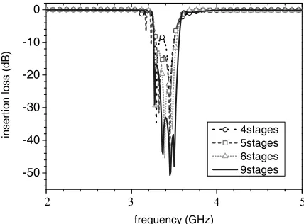
of the IDCLLR resonator, even if employ more IDCLLR pairs. The rejection bandwidth 8.7% of 9-stage filter is only 0.4% enhancement from that 8.3% of 6-stage filter.
The scheme to extend the bandwidth is uneven tuning the multi-stage IDCLLRs into slightly different resonant frequency within the forbidden band [5, 8] by means of different length of inter-digital fingers. A 9-stage prototype is designed and fabricated too as shown in Fig. 6(a). Its fingers length is 3.6 mm for the left three pairs, 3.2 mm for the middle three pairs, and 2.8 mm for the right three pairs of the IDCLLRs. The simulated and measured results of return-loss are shown in Fig. 6(b), the measured stop-band (based on rejection level at 10 dB) is observed from 3.43 GHz to 3.85 GHz with 11.5% bandwidth, centered at 3.64 GHz with −33 dB insertion loss. That is an obvious
-50 -40 -30 -20 -10 0
insertion loss (dB)
frequency (GHz)
4stages 5stages 6stages 9stages
2 3 4 5
Figure 5. Simulated insertion loss of IDCLLR-based multi-stage filters.
Table 1. Simulated stopband characteristics of IDCLLR-based stopband filter with different number of stages.
Stages Center frequency Rejection level Bandwidth 4 3.386 GHz 8.50 dB 6.7% (−8.5 dB)
5 3.393 GHz 14.4 dB 6.2% (−10 dB)
6 3.388 GHz 23.2 dB 8.3% (−10 dB)
(a)
2.0 2.5 3.0 3.5 4.0 4.5 5.0 -40
-35 -30 -25 -20 -15 -10 -5 0
insertion loss (dB)
frequency (GHz)
simulated measured
(b)
Figure 6. A 9-stage uneven-turning IDCLLR-based band-reject filter. (a) Prototype for testing. (b) Simulated and measured insertion-loss.
improvement, though the stop-band has slight shift from simulated one.
4. CONCLUSION
ACKNOWLEDGMENT
This work is supported by National Hightech Project under Grant 2007AA01Z264 of China.
REFERENCES
1. Pendry, J. B., A. J. Holden, D. J. Robbins, and W. J. Stewart, “Magnetism from conductors and enhanced nonlinear phenom-ena,” IEEE Trans. Microw. Theory Tech., Vol. 47, No. 11, 2075– 2084, Nov. 1999.
2. Marqu´es, R., F. Mesa, J. Martel, and F. Medina, “Comparative analysis of edge- and broadside-coupled split ring resonators for metamaterial design — Theory and experiments,” IEEE Transactions on Antennas and Propagation, Vol. 51, No. 10, 2572– 2581, 2003.
3. Baena, J. D., J. Bonache, F. Mart´ın, R. Marqu´es Sillero, F. Falcone, T. Lopetegi, M. A. G. Laso, J. Garcia-Garc´ıa, I. Gil, M. F. Portillo, and M. Sorolla, “Equivalent-circuit models for split-ring resonators and complementary split-ring resonators coupled to planar ransmission lines,”IEEE Trans. Microw. Theory Tech., Vol. 53, No. 4, 1451–1461, Apr. 2005.
4. Garc´ıa-Garc´ıa, J., J. Bonache, I. Gil, F. Mart´ın, R. Marqu´es, F. Falcone, T. Lopetegi, M. A. G. Laso, and M. Sorolla, “Comparison of electromagnetic band gap and split-ring resonator microstrip lines as stop band structures,”Microwave and Optical Tech. Lett., Vol. 44, No. 4, 376–379, Feb. 20, 2005.
5. Garc´ıa-Garc´ıa, J., F. Maret´ın, F. Falcone, J. Bonache, J. D. Baena, I. Gil, E. Amat, T. Lopetigi, M. A. G. Laso, M. A. M. Iturmendi, M. Sorolla, and R. Maraqu´es, “Microwave filters with improved stopband based on sub-wavelength res-onators,” IEEE Trans. Microw. Theory Tech., Vol. 53, No. 6, 1997–2006, Jun. 2005.
6. Oznazı, V. and V. B. Erturk, “A comparative investigation of srr-¨ and csrr-based band reject filters: Simulations, experiments, and discussions,” Microwave and Optical Tech. Lett., Vol. 50, No. 2, 519–523, Feb. 2008.
7. Falcone, F., F. Martin, J. Bonache, R. Marqu´es, and M. Sorolla, “Coplanar waveguide structures loaded with split ring resonators,” Microwave and Optical. Tech. Lett., Vol. 40, 3–6, Jan. 2004. 8. Mart´ın, F., F. Falcone, J. Bonache, R. Marqu´es, and M. Sorolla,
multiple tuned split ring resonators,” IEEE Microw. Wireless Compon. Lett., Vol. 13, No. 12, 511–513, Dec. 2003.
9. Jel´ınek, L., J. Mach´a˘c, and J. Zehentner, “A magnetic metamaterial composed of randomly oriented SRRs,” PIERS Online, Vol. 2, No. 6, 624–627, 2006.
10. Erentok, A., P. L. Luljak, and R. W. Ziolkowski, “Characteriza-tion of a volumetric metamaterial realiza“Characteriza-tion of an artificial mag-netic conductor for antenna applications,” IEEE Transactions on Antennas and Propagation, Vol. 53, No. 1, 160–172, Jan. 2005. 11. Schurig, D., J. J. Mock, B. J. Justice, S. A. Cummer, J. B. Pendry,
A. F. Starr, and D. R. Smith, “Metamaterial electromagnetic cloak at microwave frequencies,”Science, Vol. 314, 977–980, Nov. 10, 2006.
12. Cheng, X. X., H. S. Chen, J. A. Kong, et al., “A bianisotropic left-handed metamaterials compose of S-ring resonator,” PIERS Online, Vol. 3, No. 3, 241–245, 2007.
13. Khan, S. N., Q. L. Zhang, and S. He, “Left handed microstrip transmission line loaded with combination of split ring resonator and complementary-SRR,”Journal of Electromagnetic Waves and Applications, Vol. 22, No. 13, 1857–1863, 2008.
14. Xiao, G., J. Mao, and B. Yuan, “An artificial magnetic material with interdigital structure,” Proc. IEEE AP-S Int. Symp. Dig., Vol. 1, 2558–2561, Hawaii, USA, Jun. 10–15, 2007.
15. Alley, G. D., “Interdigital capacitors and their application to lumped-element microwave integrated circuits,” IEEE Trans. Microw. Theory Tech., Vol. 18, No. 12, 1028–1033, 1970.