ISSN (Print) : 2320 – 3765 ISSN (Online): 2278 – 8875
I
nternational
J
ournal of
A
dvanced
R
esearch in
E
lectrical,
E
lectronics and
I
nstrumentation
E
ngineering
(A High Impact Factor, Monthly, Peer Reviewed Journal)
Website: www.ijareeie.com Vol. 7, Issue 6, June 2018
Closed Loop FOPID Controlled Class E
Amplifier Fed Induction Heater System
M.P.S. Saravana Senthil
Lecturer (Senior grade), Department of ECE, Rajagopal Polytechnic College, Gudiyatham, Tamil Nadu, India
ABSTRACT: Class-E amplifier circuit is a good interface between semi converter and induction heater. The aim of this work is to improve the dynamic response of closed loop controlled class E based IH system. Circuit modeling, simulation analysis of Fractional order PID controlled class E based induction heating system described in the paper. Class -E amplifier is suggested in the present work to generate quick heat in the induction cooker. Class E amplifier is a simple system with single switch and reactive elements. The class E amplifier produces high frequency currents required by the load. Closed loop system with and without FOPID element are simulated and the corresponding results are presented.
KEYWORDS: Closed loop controlled induction heating (CLCIH), Class-F3 amplifier induction heating system (CFAIHS), Power amplifier (PA).
I.INTRODUCTION
Effect of input harmonic terminations on high efficiency class-B and class-F operation of PHEMT devices is presented by White. Device level harmonic adjust reenactments are utilized to demonstrate that high productivity can be accomplished in PHEMT class-B and class-F speakers if endeavors are made to give appropriate contribution and additionally yield consonant terminations. The simulations use a gate capacitance model which accurately describes the C/sub gs/ versus V/sub gs/ dependence for the PHEMT and are illustrated with waveform and dynamic loadline plots which relate directly to the idealized textbook view of high efficiency operation.
Optimized high-efficiency Class E radio frequency power amplifier for wide bandwidth and high harmonics suppression is given by Narendra. The performance achieved demonstrated highest harmonic suppression across wide bandwidth for VHF range according to authors' knowledge. Simulations of power performance (i.e. efficiency and output power) were verified by measurements, and good agreements were obtained[1].A New Class of High Efficiency Tuned Single-Ended Switching Power Amplifier is suggested by sokal. The new class of enhancers, named `Class E,' is characterized and is delineated by a nitty gritty depiction and an arrangement of outline conditions for one straightforward individual from the class[2].[3] A New High-Efficiency High Power Amplifier. Marconi Review is given by Tyler.
Maximum Efficiency and Output of Class-F Power Amplifiers is presented Raab. This paper extends that theory by determining the coefficients for the maximum power and efficiency possible in a class-F PA with a given set of controlled harmonics[4]. High efficiency RF and microwave solid state power amplifier is suggested by Giannini[5]. Analysis and experiments for high-efficiency class-F and inverse class-F power amplifiers is given by Young. The results show that the inverse class-F amplifier has better efficiency than that of class-F amplifiers as the on-resistance of the transistor increases. For experimental comparison, we have designed and implemented the class-F and inverse class-F amplifiers at I-GHz band using a GaAs MESFET and analyzed the measured performances[6].
ISSN (Print) : 2320 – 3765 ISSN (Online): 2278 – 8875
I
nternational
J
ournal of
A
dvanced
R
esearch in
E
lectrical,
E
lectronics and
I
nstrumentation
E
ngineering
(A High Impact Factor, Monthly, Peer Reviewed Journal)
Website: www.ijareeie.com Vol. 7, Issue 6, June 2018
off nominal operation at 50% duty ration is presented by Suetsugu. In addition various amplifier parameters such as operating frequency, output power, and load resistance range can be set as design specifications. For example, the peak switch voltage and switch current can be taken into account in the design procedure. Examples of a design procedure of the Class-E amplifier for off-nominal operation are given[10].
Design of symmetrical Class-E power amplifiers for very low harmonic-content applications is suggested by wang. The symmetrical Class E circuit, under nominal operating conditions, has extremely low harmonic distortions, and the design of the impedance matching network for harmonic filtering becomes less critical[11]. Experimental Studies on Class E Inverter based Induction Heater is given by Rama reddy[12]. Load network design technique for microwave class-F amplifier is presented by Krizhanovski[13].High-Efficiency Harmonic-Peaking Class-EF Power Amplifiers With Enhanced Maximum Operating Frequency is suggested by Thian. Two new Class-EF PA variants with transmission-line load networks, namely, third-harmonic-peaking (THP) and fifth-harmonic-peaking (FHP) Class-EF PAs are proposed in this work[14].
A new method of integration control with instantaneous current monitoring for class D series-resonant converter is given by Matysik. The results of computer simulations and laboratory experiments demonstrate that the proposed methods allow controlling the converter output quantities fulfilling soft switching conditions (zero-current switching) and provide higher efficiency in comparison to other known methods[15]. Cost effective phase shifted pulse modulation soft switching high frequency inverter for induction heating applications is presented by Kifune. Theoretical equations for the soft switching operation region are derived from the practical consideration of the gate pulse control strategy, in which the soft switching operation is limited only by the duration of dead time[16].
Modeling of planar spiral inductors between two multilayer media for induction heating applications is suggested by Acero. We demonstrate the applicability of the model by a variety of examples. We present experimental results to justify the theoretical model[17]. Behaviors of Class-F and Class-F^{-1} Amplifiers is given by Moon[18]. Power Amplifier Design Methodologies for Next Generation Wireless Communications is presented by Eswaran[19]. The Continuous Class-F Mode Power Amplifier is suggested by Carrubba. Starting from the standard class-F mode, this work shows that it is possible to maintain constant or even improved output power and efficiency for coupled variations of fundamental and second harmonic impedances[20].
A current-fed multi resonant converter with low circulating energy and zero-current switchingfor high step-up power conversion is given by Yuan[21]. Design and Analysis of Class E/F _{\bf 3} Power Amplifier with Nonlinear Shunt Capacitance at Nonoptimum Operation is presented by Hayati. Because of the increase in the design degree of freedom, one more relationship can be specified as a design specification [22]. Design equations for suboptimum operation of class E amplifier with nonlinear shunt capacitance is suggested by Kazimierczuk[23]. An example of a design procedure of the class E amplifier is given. The theoretical results were verified with PSpice simulation [24].
A Class-E RF Power amplifier with a flat-top transistor-voltage waveform is presented by sokal. This work shows a Class-E RF power amplifier designed to obtain a flat-top transistor-voltage waveform whose peak value is 81% of the peak value of the voltage of a “Classical” Class-E amplifier[25].Suboptimum operation of Class-E RF power amplifiers is suggested by Raab. This paper presents a high-power high-efficiency wideband suboptimum Class-E RF power amplifier based on a packaged high-power GaN HClass-EMT. Direct applications for this amplifier include mobile satellite communications transmitters, envelope elimination and restoration digital audio broadcasting transmitters, and power stages for primary and secondary RADAR transmitters [26].
ISSN (Print) : 2320 – 3765 ISSN (Online): 2278 – 8875
I
nternational
J
ournal of
A
dvanced
R
esearch in
E
lectrical,
E
lectronics and
I
nstrumentation
E
ngineering
(A High Impact Factor, Monthly, Peer Reviewed Journal)
Website: www.ijareeie.com Vol. 7, Issue 6, June 2018
simulation-based approach. The second harmonic input termination is shown to have a critical influence on performance, which is justified by the shape of the simulated waveforms. Experimental validation is carried out on a 2-GHz practical circuit using a medium-power packaged device[30].
High-efficiency class-F RF/Microwave power amplifiers are presented by Gao. This article provides a tutorial and review of recent developments in high-efficiency class F RF/ microwave PAs. The principles of class-F RF PAs are explained first. Recent progress in their theory and in design techniques is then presented. Different approaches of class-F PA designs are explained, and some examples of practical designs are illustrated. Finally, an attempt is made to discuss the future developments of class-F RF/microwave Pas[31]. Improved design technique of a broadband class-E power amplifier at 2GHz is suggested by Qin [32].
II. SYSTEM DESCRIPTION
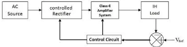
The presented induction-heating system utilizing Class-E amplifier is appeared in the Figure 1.1. DC is converted into high-frequency AC utilizing the CEAS.
Figure 1.1 Block diagram of the CEA based IH system.
III. SOFTWARE AND ARTICLE CHARGE
3.1. Existing IH system
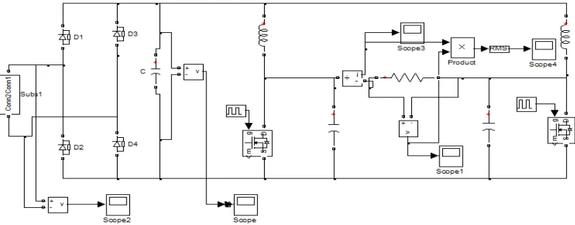
The existing system of CEIH (Class E Amplifier based Induction Heating System) is shown in the Fig1.2. DC is transformed into high frequency AC with help of class-E amplifier. Generated heat is produced due to eddy current losses. Regulating the output voltage is obtained using the PI controller.
ISSN (Print) : 2320 – 3765 ISSN (Online): 2278 – 8875
I
nternational
J
ournal of
A
dvanced
R
esearch in
E
lectrical,
E
lectronics and
I
nstrumentation
E
ngineering
(A High Impact Factor, Monthly, Peer Reviewed Journal)
Website: www.ijareeie.com Vol. 7, Issue 6, June 2018
3.2 Projected System
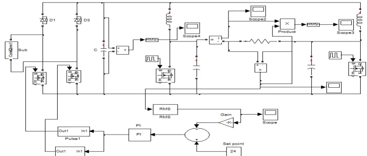
FOPID controlled closed loop Class-E Amplifier system (FOPIDCEA) is proposed to overcome CEIH is shown Fig 2.1. Low frequency AC is changed into DC with help of the controlled rectifier. The output of the rectifier is manifested into high frequency AC using the class F3 amplifier. Class-E amplifier is replaced by Class-E amplifier and PI controller is replaced by FOPID controller to improve the dynamic response.
Fig. 2.1 Block diagram of the proposed CEAIHS
1.3 System Analysis
Design calculations are performed using the following equations: The current through the load is
I =
V
dL
C
te
sin
t
..……..………. (i)The voltage across the capacitor
V =
V
d(
1
cos
t
)
.……..………. (ii) ZVS period is calculated using equation (ii)r =
fCR
3
4
1
……..………. (iii)
The value of filter capacitor is determined using the expression for ripple factor given in equation (iii).
IV. SIMULATION RESULTS
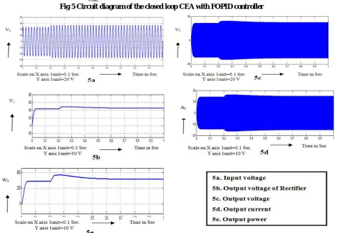
The Circuit diagram with disturbance for CEA system is appeared in Fig 3. The input voltage CEA system is shown in Fig 3a and its value is 55V. The Output voltage of Rectifier CEA system is appeared in Fig 3b and its value is 49V. The Output voltage CEA system is shown in Fig 3c and its value is 39 V. The output current CEA system is appeared in Fig 3d and its value is 15A. The output power CEA system is shown in Fig 3e and its value is 280 Watts.
ISSN (Print) : 2320 – 3765 ISSN (Online): 2278 – 8875
I
nternational
J
ournal of
A
dvanced
R
esearch in
E
lectrical,
E
lectronics and
I
nstrumentation
E
ngineering
(A High Impact Factor, Monthly, Peer Reviewed Journal)
Website: www.ijareeie.com Vol. 7, Issue 6, June 2018
Closed loop with PI controller for CEA system is appeared in Fig 4. The input voltage CEA system is shown in Fig 4a and its value is 55V. The Output voltage of Rectifier CEA system is appeared in Fig 4b and its value is 49V. The Output voltage CEA system is shown in Fig 4c and its value is 45 V. The output current CEA system is appeared in Fig 4d and its value is 17A. The output power CEA system is shown in Fig 4e and its value is 300 Watts.
ISSN (Print) : 2320 – 3765 ISSN (Online): 2278 – 8875
I
nternational
J
ournal of
A
dvanced
R
esearch in
E
lectrical,
E
lectronics and
I
nstrumentation
E
ngineering
(A High Impact Factor, Monthly, Peer Reviewed Journal)
Website: www.ijareeie.com Vol. 7, Issue 6, June 2018
ISSN (Print) : 2320 – 3765 ISSN (Online): 2278 – 8875
I
nternational
J
ournal of
A
dvanced
R
esearch in
E
lectrical,
E
lectronics and
I
nstrumentation
E
ngineering
(A High Impact Factor, Monthly, Peer Reviewed Journal)
Website: www.ijareeie.com Vol. 7, Issue 6, June 2018
Fig 5 Circuit diagram of the closed loop CEA with FOPID controller
ISSN (Print) : 2320 – 3765 ISSN (Online): 2278 – 8875
I
nternational
J
ournal of
A
dvanced
R
esearch in
E
lectrical,
E
lectronics and
I
nstrumentation
E
ngineering
(A High Impact Factor, Monthly, Peer Reviewed Journal)
Website: www.ijareeie.com Vol. 7, Issue 6, June 2018
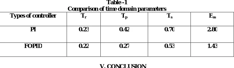
Table -1
Comparison of time domain parameters
Types of controller Tr Tp Ts Ess
PI 0.23 0.42 0.70 2.80
FOPID 0.22 0.27 0.53 1.43
V. CONCLUSION
Class E amplifier system was successfully designed, modeled & simulated using MATLAB and the results of case studies with and without FOPID system were presented. The induction heater load was shown as series combination of resistance and inductance settling time was reduced to 0.53 sec using FOPID controller. The steady state error in the output voltage was reduced from 2.80V to 1.43V by introducing FOPID controller. The results in this paper are clear indication of improvement in dynamic response. The experimental module is implemented to validate the simulation results. The benefits of Class-E system are minimum switching losses, less switching stress and high-power density. The disadvantages of Class- E system is that frequency cannot be varied by wide range.
The scope of this work was the modeling and simulation of Class-E amplifier with FOPID control. The comparison with FLC controlled system will be done in future.
REFERENCES
1. Optimised high-efficiency Class E radio frequency power amplifier for wide bandwidth and high harmonics suppression, Kumar Narendra; Tee
Yewkok IET Circuits, Devices & Systems 2014, 82 - 89
2. Sokal NO and Sokal AD. Class-E: A New Class of High Efficiency Tuned Single-Ended Switching Power Amplifiers. IEEE J. Solid-State
Circuits. 1975 June; SC-10:168-76.
3. Tyler VJ. A New High-Efficiency High Power Amplifier. Marconi Review. Fall 1958; 21(130):96-109.
4. Raab FH. Maximum Efficiency and Output of Class-F Power Amplifiers. IEEE Transactions on Microwave Theory and Techniques. 2001
June; 49(6).
5. Colantonio P, Giannini F, Limiti E. John Wiley & Sons Ltd.: High efficiency RF and microwave solid state power amplifier. 2009.
6. Young Yun Woo, Youngoo Yang and Bumman Kim. Analysis and experiments for high-efficiency class-F and inverse class-F power
amplifiers. IEEE Transactions on Microwave Theory and Techniques. 2006 May; 54(5):1969-74.
7. Bozanic M and Sinha S. Design flow for CMOS based Class-E and Class-F power amplifiers. Nairobi: AFRICON 2009. 2009; p. 1-6.
8. Kamlesh Kumar Bhartiya, Singh KP, Tiwari AN. Analysis of Push-Pull Class-E Inverter for Induction Heating. International Journal of
Engineering Research & Technology. 2012 June; 1(4): (-) e-ISSN: 2278-0181.
9. Yousefzadeh V, Wang N, Popovic Z, Maksimovic D. A digitally controlled DC/DC converter for an RF amplifier. IEEE Trans. Power
Electron. 2014; 51.
10. Suetsugu T and Kazimierczuk MK. Design procedure of Class-E amplifier for off nominal operation at 50% duty ration. IEEE Trans. Circuits
syst.I Reg. Papers. 2006 Jan; 53(7):1468-76.
11. Wang SC and Tse CK.. IEEE Trans. Circuits syst. I Reg. Papers. 2005 Aug; 52(8):16684-90.
12. Arumugam S and Ramareddy S. Experimental Studies on Class E Inverter based Induction Heater. International Journal of Computer Theory
and Engineering. 2011 April; 3(2). ISSN: 1793-8201.
13. Yefymovych A, Krizhanovski V, Giofre R and Colantonio P. Load network design technique for microwave class-F amplifier. Gdansk: 2014
20th International Conference on Microwaves, Radar, and Wireless Communication (MIKON). 2014; p. 1-3.
14. M. Thian, A. Barakat and V. Fusco, "High-Efficiency Harmonic-Peaking Class-EF Power Amplifiers With Enhanced Maximum Operating
Frequency," in IEEE Transactions on Microwave Theory and Techniques, vol. 63, no. 2, pp. 659-671, Feb. 2015
15. J. T. Matysik, “A new method of integration control with instantaneous current monitoring for class D series-resonant converter,” IEEE Trans.
Ind. Electron., vol. 53, no. 5, pp.1564–1576, Oct. 2006.
16. H. Kifune, Y. Hatanaka, and M. Nakaoka, “Cost effective phase shifted pulse modulation soft switching high frequency inverter for induction
heating applications,” Proc. Inst. Elect.Eng. , vol. 151, no. 1, pp. 19–25, Jan. 2008..
17. J. Acero, R. Alonso, J. M. Burdío, and L. A. Barragán,“ Modeling of planar spiral inductors between two multilayer media for induction heating
applications,” IEEE Trans. Magn., vol. 42, no. 11, pp. 3719– 3729,Nov.2009
18. J. Moon, "Behaviors of Class-F and Class-F^{-1} Amplifiers," in IEEE Transactions on Microwave Theory and Techniques, vol. 60, no. 6, pp.
ISSN (Print) : 2320 – 3765 ISSN (Online): 2278 – 8875
I
nternational
J
ournal of
A
dvanced
R
esearch in
E
lectrical,
E
lectronics and
I
nstrumentation
E
ngineering
(A High Impact Factor, Monthly, Peer Reviewed Journal)
Website: www.ijareeie.com Vol. 7, Issue 6, June 2018
19. U. Eswaran, H. Ramiah & J. Kanesan (2014) Power Amplifier Design Methodologies for Next Generation Wireless Communications, IETE
TechnicalReview,31:3,241-248.
20. V. Carrubba et al., "The Continuous Class-F Mode Power Amplifier," The 40th European Microwave Conference, Paris, 2010, pp. 1674-1677.
21. B. Yuan, X. Yang, D. Li, Y. Pei, J. Duan, and J. Zhai, “A current-fed multi resonant converter with low circulating energy and zero-current
switchingfor high step-up power conversion,” IEEE Trans. Power Electron., vol. 26,no. 6, pp. 1613–1619, Jun. 2011
22. Hayati, M.; Sheikhi, A.; Grebennikov, A., "Design and Analysis of Class E/F _{\bf 3} Power Amplifier with Nonlinear Shunt Capacitance at
Nonoptimum Operation," Power Electronics, IEEE Transactions on , vol.30, no.2, pp.727,734, Feb. 2015
23. T. Suetsugu and M. K. Kazimierczuk, “Design equations for suboptimum operation of class E amplifier with nonlinear shunt capacitance,” in
Proc.IEEE Midwest Symp. Circuits Syst., vol. 5, Vancouver, Canada, May 2004,pp. 560–563
24. F. You, S. He, X. Tang, and T. Cao, “Performance study of a Class-E power amplifier with tuned series-parallel resonance network,” IEEE
Trans. Microw. Theory Tech., vol. 56, no. 10, pp. 2190–2200, Oct.2008
25. Mediano and N. O. Sokal, “A Class-E RF Power amplifier with a flat-top transistor-voltage waveform,” IEEE Trans. Power Electron., vol. 28,
no. 11, pp. 5215–5221, Nov. 2013.
26. F. H. Raab, “Suboptimum operation of Class-E RF power amplifiers,” in Proc. RF Technol. Expo., Santa Clara, CA, USA, Feb. 1989, pp. 85–
98.
27. R. Beiranvand, B. Rashidian, M. R. Zolghadri, and S. M. H. Alavi, “A design procedure for optimizing the lc resonant converter as a wide
out-put range voltage source,” IEEE Trans. Power Electron., vol. 27, no. 8,pp.3749–3763,Aug.2012.
28. Z. Kaczmarczyk, “High-efficiency class E, E/F, and E/F inverters,” IEEETrans. Ind. Electron., vol. 53, no. 10, pp. 1584–1593, Oct. 2006.
29. S. D. Kee, I. Aoki, A. Hajimiri, and D. Rutledge, “The class- E/F family of ZVS switching amplifiers,” IEEE Trans. Microw. Theory Tech.,
vol. 51, no. 6, pp. 1677–1690, Jun. 2003.
30. S. Gao, P. Butterworth, S. Ooi, and A. Sambell, High efficiency class-F power amplifier design including input harmonic termination, IEEE Microwave and Wireless Components Letters, vol. 16, no. 2, Feb. 2006, pp. 81-83.
31. S. Gao, High-efficiency class-F RF/Microwave power amplifiers, IEEE Microwave Magazine, vol. 7, no. 1, Feb.2006, pp. 40-48
32. Y. Qin, S. Gao and A. Sambell, "Improved design technique of a broadband class-E power amplifier at 2GHz," in Proc. European Microwave Conf 2005, Paris, Oct. 2005, pp. 453-457
33. P.Muthu, and C.Umayal "Improved Time Responses of PI & FL Controlled SEPIC Converter based Series Resonant Inverter-fed
Induction Heating System," International Journal of Power Electronics and Drive System,Vol, 9, No. 1, March 2018, pp. 305~315
34. P.Muthu, and C.Umayal"Improved dynamic response of PFC-SEPIC converter based on induction heater using FOPID Controlled system,"