INTERFACE DEVELOPING FOR HATA MODEL USING MATLAB
NOR LIAN BINTI MOHD NORDIN
A project report submitted in partial fulfillments of the requirements for the award of the degree of Master of Electrical (Electronics and Telecommunications)
Faculty of Electrical Engineering Universiti Teknologi Malaysia
v
ABSTRACT
vi
ABSTRAK
vii
TABLE OF CONTENTS
CHAPTER TITLE PAGE
DECLARATION ii
DEDICATION iii
ACKNOWLEDGEMENT iv
ABSTRACT v
ABSTRAK vi
TABLE OF CONTENTS vii
LIST OF TABLES x
LIST OF FIGURES xi
LIST OF APPENDICES xiii
1 INTRODUCTION 1
1.0 Project Objectives 1
1.1 Problem Statement 1
1.2 Thesis Outline 2
1.3 Wireless Communication 2
1.4 Radio Spectrum Classification 3
1.5 Propagation in free space loss 6
1.6 Summary 10
2 RADIO PROPAGATION MODELS 11
2.1 Introduction 11
2.2 Types of radio propagation 12
2.2.1 Indoor Attenuations 12
2.2.1.1 Physical Effects 12
viii
b) Log Distance Path Loss Model 16
2.2.2 Outdoor Attenuations 18
2.2.2.1 Foliage Models 18
a) Weissberger’s Modeified Model 18
b) Early ITU Model 19
2.2.2.2 Terrain Models 20
a) Egli Model 20
b) Longley-Rice Model 20 c) ITU Terrain Model 21
2.2.2.3 City Models 22
a) Young Model 22
b) Okumura Model 23
c) Hata Model 27
d) Cost 231 Model 29
e) Cost 231 Walfish-Ikegami Model 30
f) Lee Model 33
2.2.3 Environmental Effects 37
a) ITU Rain Attenuation Model 37
b) Crane Model 39
2.3 Summary 39
3 SIMULATION USING MATLAB 41
3.1 Overview of Matlab 41
3.2 Why do I choose Matlab Software? 41
3.3 Graphical User Interface (GUI) 42
3.4 GUI works 43
3.4.1 Components 43
3.4.2 Figures 43
3.4.3 Callback 44
3.5 Creating and Displaying GUI 46
3.6 Summary 46
4 INTERFACE FOR HATA MODEL 47
ix
4.2 Layout for Hata Model 48
4.3 Set the properties of the button 49
4.4 M-File 50
4.5 Error Dialog Box 51
4.6 Interface for Hata Model 52
5 DISCUSSION 53
5.1 Conclusions and recommendations 53 5.2 Summary on some propagation model 55
References 56
CHAPTER 1
INTRODUCTION
1.0 Project Objectives
The objective of this project is related to the study of various prediction models for mobile radio communication system in order to predict the coverage of the base station. It also involves literature review of different prediction models available.
This project will also involve a simulation model based on propagation prediction model which the simulation will be design on Hata - Okumura Model using Matlab software.
At the end of this project, complete reports on designing simulations using Matlab will be produced.
1.1 Problem Statement
2
accurate, a design on Interface for Hata Model has to be made. This interface can be very useful for the user to make calculations without any doubt and easy.
1.2 Thesis Outline
The first chapter will be focus on basic communication where it describe radio wave propagation , studied the channel and their limitations and some basic problems such as reflection, scattering, diffraction of signal by natural and human-made structures which result to attenuation problems.
Chapter two is focus on various types of radio propagation model which will be covered Indoor and Outdoor Attenuation model. Some overview on Matlab and GUI software will be covered in chapter three. It will describe on GUI basic tools that will be used in this simulation.
The result for this project and outcomes is in chapter four which include the interface development for Hata Model. Lastly, some discussion and summary about this project is covered in the last chapter.
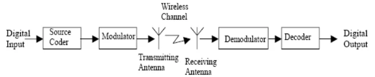
1.3 Wireless Communication
3
Figure 1.1 Block diagram of a typical Wireless Communication System
1.4 Radio Spectrum Classification
The radio spectrum is divided into sub-bands based on each frequency range's suitability for a given set of applications. Suitability is determined as a function of the atmospheric propagation characteristics of the given frequencies as well as system aspects, such as required antenna size and power limitations.
Based on these considerations, the radio spectrum has been divided into the following sub bands:
a) Extremely Low Frequency (ELF) 300 - 3000 Hz (λ =1000 - 100 km) Very Low Frequency (VLF) 3 - 30 kHz (λ =100 - 10 km)
Propagation Characteristics: Propagates between the surface of the Earth and the Ionosphere. Can penetrate deep underground and underwater. As the required antenna size is proportional to the wavelength, the large wavelength in this case mandates the use of large antennas.
Applications: mining, underwater communication (submarines), SONAR.
b) Low Frequency (LF) 30 - 300 kHz (λ =10 - 1 km)
4
Applications: broadcasting, radio navigation.
c) Medium Frequency (MF) 300 - 3000 kHz (λ =1000 - 100 m)
Propagation Characteristics: The sky wave separates from the ground wave in this range. Ground wave gives usable signal strength up to 100 km from transmitter. Applications: AM radio broadcasting (550 - 1600 kHz).
d) High Frequency (HF) 3 - 30 MHz (λ =100 - 10 m)
Propagation Characteristics: The sky wave is the main propagation mode. The ground wave is used for communication over shorter distances than the sky wave. As propagation loss increases with frequency increases, the use of repeaters is required.
Applications: Broadcasting over large areas, amateur radio (ham), citizens band (CB) radio.
e) Very High Frequency (VHF) 30 - 300 MHz (λ =10 - 1 m)
Propagation Characteristics: Diffraction (bending of waves due to obstruction) and reflection give rise to communication beyond the horizon. Propagation distances are thousands of kilometers. The diffraction and reflection enables reception within buildings.
Applications: broadcast TV, FM radio (88 - 108 MHz), radio beacons for air traffic control.
f) Ultra High Frequency (UHF) 300 - 3000 MHz (λ =1 m - 10 cm)
Propagation Characteristics: Reflections from atmospheric layers are possible. Effects of rain and moisture are negligible.
5
g) Super High Frequency (SHF) 3 - 30 GHz (λ =10 - 1 cm)
Propagation Characteristics: Range becomes limited by obstacles as frequency increases. Propagation is limited by absorption by rain and clouds.
Applications: Satellite service for telephony and TV, mobile services in the future.
h) Extremely High Frequency (EHF) 30 - 300 GHz (λ =10 - 1 mm)
Propagation Characteristics: Very high losses due to water, oxygen, vapor. Applications: communications at short distances (within line of sight), broadcast satellite for HDTV (for communication between satellites in space, not space to earth).
6
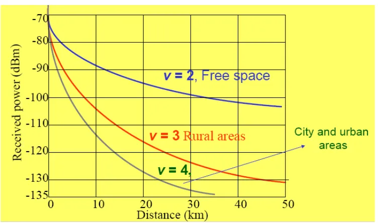
1.5 Propagation in free space loss
Propagation in free space is the ideal. Generally the received power can be expressed as:
For non-Line of sight received power at any distance d can be expressed as:
[
]
+
=
d
d
v
d
P
d
P
r(
)
10
log
10 r(
ref)
10
log
10 refFigure 1.3 Received power for different value of Loss parameter v
Path Loss formula is expressed as:
(1.1)
(1.2)
7
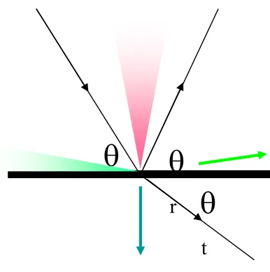
When propagation takes place close to obstacles, the following propagation mechanisms occur:
Figure 1.4 Mechanisms of propagation model
a) Reflection will occur when a radio wave strikes an object with dimensions that are large relative to its wavelength, for example buildings. Perfect conductors will reflect with no attenuation. Dielectrics reflect a fraction of incident energy such as “Grazing angles” reflect max and steep angles transmit max. (max -The exact fraction depends on the materials and frequencies involved). The reflection induces 180° phase shift.
When electrical signal propagating through a medium impinges on a different medium with different electrical characteristics, the electrical signal is partly reflected back to the previous media and part of the signal is transmitted through the obstructing medium. If the signal is propagating through a dielectric medium, there is no absorption of the signal due to reflection. Otherwise part of the energy of the signal will be absorbed by the medium. If the reflected media is a perfect conductor, all energy of the signal is reflected back to the first medium.
8
Figure 1.5 Reflection mechanisms
b) Diffraction
Diffraction will occurs when a radio wave is obstructed by surfaces with irregularities. Diffraction allows radio signals to propagate around the curved surface of the earth and that in turn allows the propagation to travel behind a building or obstruction. The received signal drops significantly as the receiver moves deep behind an obstruction. The phenomenon of diffraction is explained by Huygen’s principle. It states that all signal points on the signal wave acts as a point source to produce the secondary signal waves that travels in the direction of propagation.
Secondary waves arise from the obstructing surface and give rise to the bending of waves around and behind obstacles. “Secondary” waves propagated into the shadowed region. This make the excess path length results in a phase shift. Fresnel zones relate phase shifts to the positions of obstacles. These secondary waves reaches the shadowed region of the obstruction and the vector sums of all these secondary waves provides the signal to the receiver.
The phase difference between the direct line of sight path and the diffracted path depends upon the height of the obstruction and the locations of the transmitter and receiver.
θ
θ
r
θ
9
Figure 1.6 Difraction mechanisms.
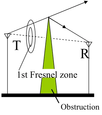
c) Scattering
Scattering will occurs when a radio wave travels through a medium containing lots of small (compared to wavelength) objects.
The actual signal received at a mobile station, is often stronger than the signal strength estimated by considering reflection and diffraction of signals. The reason for this is the Scattering. When radio waves hits a rough surface, the reflected energy is scattered in different directions. Many natural objects like trees and man-made structures like electrical lamp posts scatter radio energy in all directions. This scattered signal reaches the receiver and increases the signal strength. The scattering depends upon the roughness of the surface. Surface Roughness is stated in terms of the Rayleigh criteria, defined in terms of critical height (hc) of surface protuberances for given incident angle of reflection(θi)
hc = l / 8SinθI (1.4)
A surface is considered smooth if its minimum to maximum protuberances is less than hc. and it is considered rough when the minimum to maximum
protuberances is more than hc . On rough surface, the reflected signal energy is
reduced due to this scattering effect. For distant objects, where the physical location
T
R
1st Fresnel zone
10
of the object is known, Radar Cross Section Model of the object can be used to predict the scattering effect.
1.6 Summary
Radio waves are a form of electromagnetic radiation, which was discovered in the late 19th century. The branch of physics that describes how antennas and radiation behave is called electrodynamics. Many design decisions in layers above wave propagation are affected by the issues mentioned.
There are several factors have to be taken into account in deciding what frequency band should be used for a particular type of radio communication service. Operating frequencies must be chosen in a region of the RF spectrum where it is possible to design efficient antennas of a size suitable for mounting on base station masts, vehicles and on hand portable equipment. Since the mobiles can moved around freely within the area covered by the radio system, their exact location is unknown and the antennas must therefore radiate energy uniformly in all directions.
Based on the fact that each individual telecommunication link has to encounter different terrain, path, obstructions, atmospheric conditions and other phenomena, it is impossible to formulate the exact loss for all telecommunication systems in a single mathematical equation. As a result, different models exist for different types of radio links under different conditions. The models rely on computing the median path loss for a link under a certain probability that the considered conditions will occur.
56
REFERENCES
1. Alouini, Mohamed-Slim and Simon, Marvin. (December 1998). .A Unified Approach to the Probability of Error for Noncoherent and Differentially Coherent Modulations Over Generalized Fading Channels.. IEEE
Transactions on Communications, vol. 46, no. 12, 1625.1637.
http://wsl.stanford.edu/~ee359/unified_non.pdf
2. A. Medeisis, A.Kajackas (May 2000), On the Use of the Universal
Okumura- Hata Propagation Prediction Model in Rural Areas, IEEE
Vehicular Technology Conference Proceeding,Vol. 3, pp. 450-453. Aragon, Alejandro. (August 2000). .MCU Programmable RF Transmitter..
Centre for Communication Systems Research, 1.3.
http://www.ee.surrey.ac.uk/Personal/A.Aragon/mcutrx.html
3. Bhatti, Saleem. (March 1995). .The Electromagnetic Spectrum; Propagation in Free-Space and the Atmosphere; Noise in Free-Space.. University
College London, 1.4. http://www.cs.ucl.ac.uk/staff/S.Bhatti/D51- notes/node22.html
4. Burt, Dennis. (no date). .Creating Better Coverage in Buildings and Tunnels..
Multiradio S.A. Online, 1-6.
http://www.multiradio.com/Notas/Nota-andrew3.html
5. COST231 (1999), final report.
6. DeHaan, J and Jacobs, M.L. (January 1998). .Project Notes 8450-98-06, Tunnel Communications Test Results.. United States Department of Interior, Bureau ofReclamation.
http://www.usbr.gov/hydrores/publications/tunnelrpt.pdf
7. DuBroff, Richard E., Marshall, Stanley V., and Skiteck, Gabriel G. (1996).
Electromagnetic Concepts and Applications (Fourth Edition), Prentice-Hall, Saddle River, New Jersey,665.
8. Hashemi, Homayoun. 1993. .The Indoor Radio Propagation Channel..
57
Technology Research Institute. (July 2000). .Propagation Models for UrbanEnvironment.. WTEC Hyper-Librarian, 1.4.
http://itri.loyola.edu/wireless/04_02.html
9. H. Bertoni (2000), Radio Propagation for Modern Wireless Systems, Prentice Hall, 258 p.
10. J. Rissanen (2003), Dynamic resource reallocation in cellular networks, master thesis.
11. K. Siwiak (1998), Radiowave Propagation and Antennas for
Personal Communications, Artech House, 418 p.
12. Laitinen, Heikki. (1999) .Verification of a Stochastic Radio Channel Model Using Wideband Measurement Data.. Helsinki University of
Technology, Master.s Thesis, 3.11.
http://www.vtt.fi/tte/rd/propagation/Mthesis.pdf
13. Linmartz, Jean-Paul. (1996). .Radio Propagation Models.. Wireless Communication, vol.1, no.1, 1.36.
http://www.deas.harvard.edu/~jones/cscie129/prop_models/ propagation.html
14. Moayeri, Nader and Wie, Zhang. (1999). .Formations of Multiple Diffraction by Buildings and Trees for Propagation Prediction.. IEEE 802.16
Broadband Wireless Access WorkingGroup 802.16cc-99/28. 1
(November): 1,5. In-Building/In-Tunnel User Considerations C-2 August 2002
15. Mohan, Ananda and Suzuki, Hajime. (July 2000). .Measurement and Prediction of High Spatial Resolution Indoor Radio Channel
Characteristic Map.. IEEE Transactions on VehicularTechnology, vol. 49, no.4, 1321.1333. http://www.ieee.org/organizations/
pubs/pub_preview/VT/49vt04_toc.html
16. Mohan, Ananda, Suzuki, Hajime, Wang, James, and Yabe, Hatsuo. (September 1996). .Measurement and Prediction of Two-Dimensional Fading Map in a Hallway.. IEEETransactions on Communication, vol. E79-B, no. 9, 1192.1198. http://www.ee.uts.edu.au/~hajime/
58
Propagation Environment.. IEEECommunications Surveys & Tutorials, http://www.comsoc.org/pubs/surveys/3q00issue/neskovic.html
18. Nilsson, Martin, Slettenmark, Jesper, and Beckman Claes. (1998). .Wave Propagation in Curved Road Tunnels.. IEEE AP-S International
Symposium. http://rf.rfglobalnet.com/library/Papers/files/7/apstunnels.pdf 19. Orange, Matthew. (March 1998). .Propagation in Outdoor Cellular and
In-Building Pico- Cellular Systems.. Packetised Wireless Communication
Systems in Interference LimitedEnvironments, 35.50.
http://www.ele.auckland.ac.nz/students/orange/thesis/toc_final.pdf 20. Rapport, Theodore S. (1998). Wireless Communications: Principles &
Practices, Prentice Hall PTR, Saddle River, New Jersey, 140.141.
21. R. Vaughan, J. Bach Andersen (2003), Channels, Propagation and
Antennas for Mobile Communications, IEE, 753 p.
22. Saunders, Simon. (1999 & 2000). Antennas and Propagation for Wireless Communication Systems. Chichester, West Sussex, England: John Wiley & Sons Ltd.
23. SSS Online. (January 2001). .Introduction to Indoor Radio Propagation..
Spread Spectrum Scene, 1.6. http://sss-mag.com/indoor.html
24. Thompson, Richard. (2000). .Introduction to HF Radio Propagation.. IPS Radio & Space Services, 1.28.
http://www.ips.gov.au/papers/richard/hfreport/webrep.html
25. Tripathi, Nishith, Reed, Jeffrey, and Van Landingham, Hugh. (December 1998). .Handoff in Cellular Systems.. IEEE Personal Communications, 26.36. http://ntrg.cs.tcd.ie/htewari/papers/tripathi98.pdf
26. W. Backman (2003), Error Correction on Predicted Signal levels in Mobile
Communications, master thesis.