The views expressed herein are those of the authors and do not represent an official position of the U.S. NRC or Battelle Memorial Institute.
Advances in COD Equations – Multiple Loading Modes:
Validation of the Analytical Models to Experimental Data
Andrew J. Cox1, Bruce A. Young2, and Paul M. Scott3
1Research Scientist, Battelle Memorial Institute, Columbus, OH ([email protected]) 2Principal Research Scientist, Battelle Memorial Institute, Columbus, OH
3Research Leader, Battelle Memorial Institute, Columbus, OH
ABSTRACT
Non-linear fracture mechanics equations for through-wall cracks (TWC) in a pipe are used to analyze nuclear piping systems for either critical flaw size or critical loading conditions as part of probabilistic Leak-Before-Break (LBB) failure analyses. These probabilistic codes use a large number of independent solutions to determine an overall assessment of system failure probability. For each individual realization, if a TWC is determined to be present, the solution requires an estimation of the crack opening displacement (COD) for the postulated TWC as part of a leak rate evaluation.
Updated analytical COD equations have been proposed in Young at al. (2012) and Young at al.
(2013). These updated equations were based on the GE-EPRI formulation for COD found in Kumar, V. and German, M. D. (1988) and Rahman et al. (1998-1,2,3). The updated solutions utilized significant advancements in computational capability and speed, such that, structural finite element analyses (FEA) were completed using three-dimensional 20-node continuum brick elements. The results of the FEA provided the basis to determine analytical functions which incorporate axial load due to internal pressure, crack face pressure, and applied bending moment for a solution which provides through-thickness variations in COD for a wide range of normalized crack lengths and pipe R/t ratios.
While validation of the analytical equations to non-linear FEA have been provided in the previously published papers such as Young et al. (2012) and Young et al. (2013), this paper focuses on the validation of the analytical solutions to experimental results. For the experimental data, a suite of experiment results ranging from pure tension to tension plus bending were used from the Pipe Fracture Database developed in Wilkowski et al. (1995).
INTRODUCTION
As computational memory and speed increase, LBB evaluations in the nuclear piping industry have transitioned from a deterministic basis to a probabilistic framework. Thus, accurately characterizing the best-estimate leak rate has become increasingly important. As LBB evaluations become more refined, the ability for standardized leak rate codes, such as the
Seepage Quantification of Upsets in Reactor
Tubes
(SQUIRT) code (Paul et al. (1994)), to accept through-thickness variations in crack-opening displacement (COD) values has become more common.As a result of the limitations with the existing GE-EPRI type methods for predicting COD values for TWCs in pipes, such as limitation of crack size, fixed pressure for combined pressure and bending solutions, and no through thickness variation in COD, the development of a comprehensive COD prediction tool for combined loadings applicable to a wide range of piping systems was undertaken. To provide solutions more close to actual plant applications, the loading assumption in the present work is that the axial load (due to internal pressure) and the crack face pressure are prescribed concurrently with the moment being applied subsequent to the internal pressure.
(2013) provides an overview of the technical basis for the equations being validated in this paper.
THEORY
While the detailed theory of the COD equations for through-wall cracks in a pipe is provided in Young
et al. (2013), some of the equations are shown in this section for completeness. The loading assumption is that the axial load (due to internal pressure) and the crack face pressure are applied concurrently with the moment applied subsequent to the internal pressure. Unlike previous solutions, there is no restriction that the pressure be a fixed, predetermined value.
For axial loading of a pipe with a through-wall crack (TWC), a failure surface approach for the loading condition of concurrent axial load (due to pressure in an end-capped pipe) (Pip) and crack face pressure
(PCFP) was proposed as shown in Equation 1. The limit load (Po) (i.e. the load at which the un-cracked
ligament becomes a fully plastic hinge) for a pipe with a through-wall crack under axial load is given in Equation 2 as a function of the yield stress ( ), the mean radius of the pipe (Rm), the pipe thickness (t),
and the half-crack size in radians (θ).
(1)
(2)
Since the crack face pressure is equal to the internal pressure on the inner diameter of the pipe and zero on the outer diameter of the pipe, a first order approximation was made such that the crack face pressure is equal to a linear fraction of the internal pressure (
). The far-field stress value ( , due to the
combined internal pressure and crack face pressure, to calculate the elastic COD is provided in Equation 3 as a function of the internal pressure (pi), the mean radius of the pipe (Rm), the inner radius of the pipe
(Ri), the pipe thickness (t), the fraction of the internal pressure (
with the assumption of no externally
applied axial loads.
(3)
To mimic the behavior in a physical nuclear piping system, an assumption was made that the internal pressure and the crack face pressure were applied concurrently; such that, the load ratio ( ) given in Equation 4 is constant for a given crack size and pipe geometry. Thus, Equation 1 can then be rewritten as Equation 5.
(4)
Using a failure surface approach, the load ratio, , and the load due to the internal pressure,
, an
effective limit-load expression is derived and shown in Equation 6.
(6)
The GE-EPRI formulation for the analytical COD equations separates the elastic and plastic solutions as shown in Equation 7. If we assume the axial load comes from the internal pressure on an end-capped pipe with a through-wall crack, the total displacement equation is Equation 8 provided by Young et al.
(2012). To satisfy continuity, when the crack face pressure is zero (i.e.,
), the equation must collapse to GE-EPRI Equation. Thus, the plastic influence functions for the solution with crack face pressure must be equal to the plastic influence functions without crack face pressure. Values for the plastic influence function, , and the elastic influence functions, , are provided in Young et al. (2012). The solution in Equation 8 is expressed as functions of half crack length (a), Young’s modulus (E), reference strain ( ), Ramberg-Osgood fitting coefficient ( ), and the Ramberg-Osgood strain-hardening exponent ( ).
(7)
(8)
Since there are differences between long through-wall cracks and short through-wall cracks, mainly consisting of the in-plane rotation under pressure, adjustments are required to the analytical solution. The first adjustment is a fitting term as a function of the normalized crack length. For short cracks the pipe neutral axis is outside the crack plane, while for long cracks the pipe neutral axis is inside the crack plane. This difference creates a phenomenon which requires crack opening corrections for the crack face pressure portion of the equation ( ).
The second adjustment is due to the way the analytical solutions for the GE-EPRI model are derived (i.e. under the small scale yielding assumption). When finite element calculations are performed to compensate for relatively large displacement phenomenon, which provides a closer approximation to reality, the rotation the cap-ended pipe is increased. Thus, a second fitting term based on the strain hardening parameter is required for a reduction in analytic model to finite element error ( ). Recasting the elastic-plastic solution with the correction factors is shown in Equation 9.
(9)
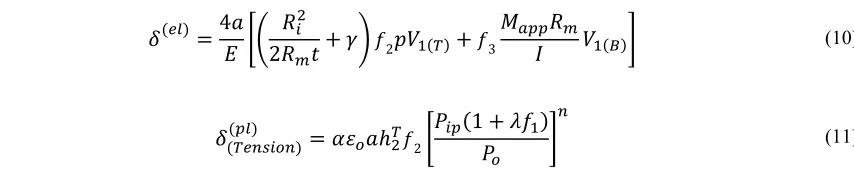
(10)
(11)
A concept of equivalent moment is now introduced. This equivalent moment (Meq) is the moment
required to obtain the same plastic COD in Equation 11. For reference, the limit moment (Mo) (i.e. the
moment at which the un-cracked ligament becomes a fully plastic hinge) for a pipe with a through-wall crack under moment loading is given in Equation 12. The equivalent moment is then determined using the plastic COD equation given in Young at al. (2012) and recasting it as Equation 13.
(12)
(13)
Once the equivalent moment is determined for the plastic COD due to tension, a total effective moment ( ) can be calculated using the equivalent moment (Meq) and the applied moment (Mapp) as
shown in Equation 14. Equation 15 provides the final solution in terms of the GE-EPRI method of the elastic COD plus the plastic COD.
(14)
(15)
The details of the validation of Equation 15 to experimental data are provided in the next section.
VALIDATION
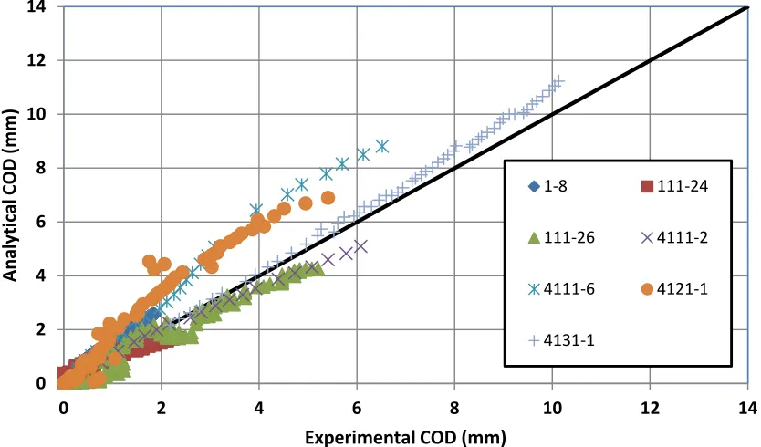
Seven full-scale pipe test experiments from the Pipe Fracture Database, developed by Wilkowski et al.
Table 1. Characteristics of the Circumferential Through-Wall Crack Experiments
Specimen ID 4131-1 4121-1 4111-6 111-24 4111-2 111-26 1-8
Base Material 304 SS 304 SS A516 Gr70 / CS SA 333 Gr6 / CS A155-KC60 / CS 316L SS A106 Gr-B / CS
Weld No No No Yes No No No
OD (mm) 166.4 168.1 910.1 612.0 711.0 106.2 399.3
Wall (mm) 13.4 12.9 72.84 31.3 23.6 8.3 26.2
0.370 0.386 0.370 0.079 0.37 0.244 0.120
Temperature (C) 287.8 287.8 287.8 287.8 287.8 21 287.8
Internal Pressure (MPa) 17.235 Increase 0 0 0 0 15.5
Gamma 0 0 0 0 0 0 1
Rm/t 5.71 6.02 5.75 9.28 14.6 5.9 7.12
Yield (MPa) 139.0 139.0 210.0 229.0 231.0 254.0 216.5
UTS (MPa) 450.0 450.0 510.0 525.0 544.0 532.0 506.1
Alpha 9.69 9.69 2.07 2.14 1.15 5.50 2.37
N 3.13 3.13 5.20 4.36 5.55 4.76 4.03
E (GPa) 182.9 182.9 206.3 200.0 206.3 157.5 206.3
(MPa) 294.5 294.5 360.0 377.0 387.5 393.0 361.1
Span (Inner) (mm) 1220 N/A 3350 3350 3350 610 3350
Span (Outer) (mm) 3200 N/A 11580 11580 11580 1524 11580
Ro (mm) 83.2 84.1 455.1 306.0 355.5 53.1 199.7
Rm (mm) 76.5 77.6 418.6 290.4 343.7 49.0 186.6
Ri (mm) 69.8 71.2 382.2 274.7 331.9 44.8 173.5
Test Type
IP – Increasing Pressure FP – Fixed Pressure 4B – 4pt Bend
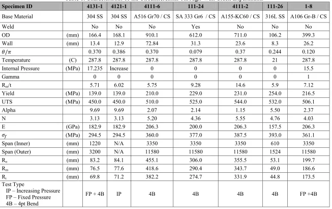
To determine if any experimental-factor correction was required to be applied to Equation 15, an initial comparison was made to the seven experiments shown in Table 1. The results of the initial comparison are shown in Figure 1. Based on this comparison and similar results obtained by Kim et al.
(2001) and Kim et al. (2002) an experimental correction factor was developed.
Figure 1. Comparison of Equation 15 to the Experimental Data
Corrected Comparison
The analysis of data involved reviewing the contributions of elastic COD and plastic COD provided by Equation 15. Based on this review, the correction factor (f4) provided in Equation 16 was implemented. A
new set of plastic COD equations was implemented for the plastic COD portions as shown in Equations 17 through 19 with Equation 19 being the final solution implemented in the updated CALC_COD
software.
(16)
(17)
(18)
0 2 4 6 8 10 12 14
0 2 4 6 8 10 12 14
Ana
ly
ti
ca
l C
OD
(mm
)
Experimental COD (mm)
1-8 111-24
111-26 4111-2
4111-6 4121-1
(19)
While separating the experimental correction factor (
f4
) from the base equations as shown in
Equations 17 through 19 was the method shown here, the net effect of this correction is
increasing the limit moment and limit load by 15 percent (i.e. increasing the effective yield
strength by 15 percent). Using Equation 19, the data for the experiments shown in Table 1 were
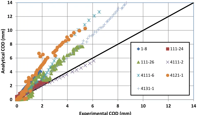
used for validation. Figure 2 shows the results of the final validation of Equation 19. As can be
seen in comparing Figures 1 and 2, the agreement between the analytical CODs and the
experimental CODs is much better when this correction factor (
f4
) is used.
Figure 2. Comparison of Equation 19 to the Experimental Data
CONCLUSIONS
The work reported in this paper is a validation of the research by Young et al. (2012) and Young et al. (2013) with experimental results. Several key elements to provide a validation of the analytical solution are provided.
The following items are a list of key conclusions from this portion the current study.
Based on work in Young et al. (2013), the COD functions are dependent on the rotation characteristics provided by the boundary conditions. Functions to compensate for the crack size as well as the rotation as a function of material characteristics have been developed and implemented.
0 2 4 6 8 10 12 14
0 2 4 6 8 10 12 14
Ana
ly
ti
ca
l C
OD
(mm
)
Experimental COD (mm)
1-8 111-24
111-26 4111-2
4111-6 4121-1
implemented in the updated CALC_COD subroutine. This includes the experimental correction factor provided in this paper in Equation 16.
With respect to the final solution, the solution estimates the COD for a pipe which is free to rotate at the ends. In reality, the pipe is restrained at the pipe-ends which in turn causes smaller COD values than reported. Together with the current leak-rate software, this may cause a non-conservative result with respect to pipe rupture probabilities. Application of restraint of pressure induced bending results should be investigated such as found in Rahman, S. et al. (1998-3), Kim et al. (2007), Olson et al. (2003), and Feng et al. (2001).
ACKNOWLEDGMENTS
This work was conducted at Battelle Columbus as part of the NRC’s Piping Integrity Program. The authors would like to thank the NRC’s Office of Research for their support of this program.
NOMENCLATURE
REFERENCES
Feng, Z., Miura, N., Ghadiali, N., Brust, F., Santos, T., Choi, J.B., Park, C.Y., and Wilkowski, G. (2001). “Effects of Pipe-System Restraint on COD Calculations of Axial Loaded Pipes for LBB Applications – Finite Element Round Robin Results,” Structural Mechanics in Reactor Technology (SMiRT) 16, Washington, DC
Kim, J.-W. (2007). “Evaluation Model for Restraint Effect of Pressure Induced Bending on the Plastic Crack Opening of a Circumferential Throough-Wall Crack,” Nuclear Engineering Technology, Vol. 39, No. 1, pp. 75-84.
Pip Axial Load due to Internal Pressure Collapse Bending Moment
PCFP Axial Load due to Internal Pressure Crack face pressure to internal pressure ratio
Collapse Tension Force Load Ratio
Reference Stress COD
Mean Pipe Radius Elastic COD
Pipe Thickness Plastic COD
Crack Angle (total crack angle = 2θ ) Crack Length (total length = 2a) Inner Radius of Pipe Strain Hardening Exponent Internal Pipe Pressure Strength Coefficient
Crack Face Pressure Reference Strain
Far-Field Tension Stress Plastic Influence Function
Cross-Section of Pipe Young’s Modulus Applied Axial Far-Field Force Elastic Influence Function
Applied Bending Moment Elastic Influence Function for Tension
Loading
Equivalent Bending Moment Elastic Influence Function for Bending Effective Bending Moment (Meq +
Mapp)
Kim, Y.-J, Huh, N.S, and Kim, Y.-J. (2001). “Enhanced reference stress based J and COD estimation method for LBB analysis and comparison with GE/EPRI method,” Fatigue Fract Engng Mater Structure, Vol. 24, pp. 243-254.
Kim, Y.-J., Huh, N.S, and Kim, Y.-J. (2002). “Reference stress based elastic-plastic fracture analysis for circumferential through-wall cracked pipes under combined tension and bending,” Engineering Fracture Mechanics, Vol. 69, pp. 367-388.
Kumar, V. and German, M.D. (1988). “Elastic-Plastic Fracture Analysis of Through-Wall and Surface Flaws in Cylinders,” EPRI Report NP-5596, Research Project 1237-5
Paul, D.D., Ahmad, J., Scott, P.M., Flanigan, L.F., and Wilkowski, G.M. (1994). “Evaluation and Refinement of Leak-Rate Estimation Models,” NUREG/CR-5128, BMI-2164 Rev. 1, June 1994
Olson, R.J., Morbitzer, R.A., Scott, P.M., and Wilkowski, G.M. (2003) “Practical Application of Restraint of Pressure-Induced Bending Phenomenon in Leak Rate Calculations,” Structural Mechanics in Reactor Technology (SMiRT) 17, Prague, Czech Republic
Rahman, S., Brust, F.W., Ghadiali, N., and Wilkowski, G.M. (1998-1). “Crack-Opening-Area Analyses for Circumferential Through-wall Cracks in Pipes – Part I: Analytical Models,” International Journal of Pressure Vessels and Piping, Vol. 75, pp. 357-373.
Rahman, S., Brust, F.W., Ghadiali, N., and Wilkowski, G.M. (1998-2). “Crack-opening-area analyses for circumferential through-wall cracks in pipes – Part II: model validations,” International Journal of Pressure Vessels and Piping, Vol 75 (1998), pp. 375-396.
Rahman, S., Ghadiali, N., Wilkowski, Moberg, F., and Brickstad, B. (1998-3). “Crack-opening-area analyses for circumferential through-wall cracks in pipes – Part III: off-center cracks, restraint of bending, thickness transitions and weld residual stresses,” International Journal of Pressure Vessels and Piping, Vol 75 (1998), pp. 397-415.
Rudland, D.L., Wang, Y.-Y., and Wilkowski, G.M. (2002). “Comparison of crack-opening predictions for LBB applications,” International Journal of Pressure Vessels and Piping, Vol. 79, pp. 209-217
Wilkowski, G.M., Ghadiali, N., Rudland, D., Keishnaswamy, P., Rahman, S., and Scott, P. (1995) “Short Cracks in Piping and Pipe Welds: Seventh Program Report March 1993 – December 1994,” NUREG/CR-4599, BMI-2173, Vol. 4, No. 1.
Young, B.A., Olson, R.J., and Kerr, M. (2012). “Advances in COD Modeling: Circumferential Through-Wall,” ASME International, PVP 2012, PVP2012-78181, Toronto, ON, Canada