Simulation of PV based Z-source DVR for
Power Quality Improvement
DAMALLA SAILAJA M-tech Student Scholar
Department of Electrical & Electronics Engineering, Laqshya Institute of Tech. and Sciences, Tanikella;
Khammam (Dt); Telangana, India. Email id: [email protected] m
Mr. T. HUSSAIN Assistant Professor
Department of Electrical & Electronics Engineering, Laqshya Institute of Tech. and Sciences, Tanikella;
Khammam (Dt); Telangana, India Email: [email protected]
Abstract-- This paper proposes a photovoltaic (PV) system, which exhibits a set of benefits when draw parallels to conventional stand-alone PV system. In the present system, the generated energy by the PV arrays is managed by multi-string step-up converters. Voltage swell and sag is big brain-teasers in power system. Sensitive load has a serious effect on itself due to voltage swell and sag. Dynamic Voltage Restorer (DVR) is a power conventional appliance used in power distribution network. Various equivalent circuit models of a PV cell have been proposed. For obtaining high power, numerous PV cells are connected in series and parallel on a panel, which is a PV module. A PV array is defined as a group of several modules electrically connected in series-parallel combinations to generate the required current and voltage. The dynamic voltage restorer (DVR) has become renowned as a cost competent conclusion for the security of sensitive loads from voltage swells and sags. Power quality is one of the considerable attention in the existing power system environment. Dynamic Voltage Restorer (DVR) is a modified power apparatus that is utilized to enhance voltage stability i.e. to minimize the power quality problems in electrical power system network. The suggested control scheme is elementary to model and has outstanding voltage compensation capabilities, through hysteresis voltage control technique is efficacious of proposed technique is examined through computer simulation. To felicitously control the control objectives for compensation voltage control, primarily the power circuit of a DVR system is analyzed with PV system. The model is humble. The Simulation results are fetched out by Simulink/Matlab to verify the performance of the present method.
Key words- Dynamic Voltage Restorer (DVR), Photovoltaic (PV) system, Voltage Sags, Voltage Swells, Sensitive Load, VSI, Sy nchronous Reference Frame Theory
I. INTRODUCTION
Today photovoltaic (PV) power systems are turn into more and mo re famous, with the g rowth of energy requirement and the matter of ecosystem pollution around the planet. Four d issimilar system configurations are extensively progressed in grid -connected PV power applications: the module-integrated inverter system, the centralized inverter system, the multi-string inverter
system and the string inverter system. Chiefly three kinds of inverter systems except the centralized inverter system can be involved as small-scale distributed generation (DG) systems, such as residential power applications. The most chief model limitation of the PV DG system is to attain a high voltage gain. For a characteristic PV module
Power Quality conundrums cover a extensive range of disruptions such as voltage swells/sags, harmonics distortion, flicker, interruption and impulse transients [1]. Vo ltage sags can exists at any mo ment of time, with amp litudes extending fro m 10 – 90% and a duration lasting for half a cycle to one minute [3]. Vo ltage swell, on the other hand, is explained as a swell is exp lained as an rise in current or rms voltage at the power frequency for durations from 0.5 cycles to 1 minute. Characteristic magnitudes are between 1.1 and 1.8 pu. Swell magnitude is also explained by its persisting voltage, in this case, always greater than 1.0. [2,3,4]. Stability limits exp lain the extreme electrical power to be transferred without causing devastation to electric appliances and transmission lines. In princip le, regulations on power transmission can always be dimin ished by the addition of new generation and transmission facilities. A lternatively, FACTS controllers can allo w the same goals to be met with no chief adaptations to system layout. The potential benefits brought about by FACTS controllers include reduction of operation and transmission investment cost, increased system security and reliability, increased power transfer capabilities, and an overall enhancement of the quality of the electric energy delivered to customers
results can be very costly for the customer, ranging fro m minor quality alterations to production downtime and apparatus damage [5-7]. There are many conflicting methods to mitigate voltage swells and sags, but the use of a convention Power appliance is examined to be the most productive method. Energ izing a large capacitor bank or Switching off a large inductive load is a characteristic system event that results swells [1]. This paper introduces Dynamic Voltage Restorer and its operating principle. Then, a simple control based on Hysteresis voltage control method is used to compensate voltage swells/sags. At the end, MATLAB/SIMULINK model based simu lated results were extant to certify the productiveness of the suggested control method of DVR. Vo ltage sag is the most serious power quality conundrums faced by industrial customers. Vo ltage sag is familiar causes for malfunctioning in production plants. Vo ltage sag is short term shrinkage in voltage magnitude. According to IEEE standard 1159 voltage sag is “a decrease in RMS voltage between 10 to 90 % at a power frequency for durations from 0.5 cycles to 1 minute”.
Fig.1. Basic Components of a DVR
During voltage sag, the DVR in jects a voltage to restore the load supply voltages. The DVR needs a source for this energy. Two types of system are considered; one using stored energy to supply the delivered power as shown in Figure1, and the other having no internal energy storage. There are a number of voltage swell/sag mitigating schemes available but the use of custom power service is deliberated to the most productive scheme. Th is paper introduce basic concept of DVR (Dynamic Vo ltage Restore). DVR in ject an compatib le voltage magnitude with an co mpatible phase angle dynamically [4]. Dynamic compensating signals are determine based on the difference between desired and actual values [5]. Main components of DVR are voltage source converter, injecting transformer, passive filter, and energy storage device. The performance of DVR depends on the efficiency control technique of switching of voltage source inverter (VSI). In th is paper Hysteresis Voltage control based simp le control method is used to compensate voltage sag/swell.
II. SYSTEM DISCRIPTION
DVR is a power electronic based device that injects voltage into the system to control the load side voltage. It is normally situated between supply and critical load feeder. The basic function of DVR is to boost up the load side voltage in the occurrence of interference in order to elude any power disturbance to the load. There are many control technique available to imp lement the DVR. The primary function of DVR is to compensate voltage sags and swells but it can also perform the tasks such as: harmonic co mpensation, reduction of transient in voltage and fault current limitation. The main parts of DVR are injection transformer, harmonic filter, a voltage source converter, energy storage device and control & protection system.
Fig.2. Basic Principle of DVR
Fig.2. shows the basic co mpensation principle o f dynamic voltage restore. A voltage source inverter (VSI) is used as the series active power filter. This is controlled so as to draw or in ject a co mpensating voltage Vinj fro m o r to the
supply, such that it cancels voltage harmonics on the load side i.e. this dynamic voltage restore (DVR) generates the distortions opposite to the supply harmonics.
Fig.3.Waveforms for the supply voltage, desired load voltage and the compensating voltage
principle o f series active power filter to eliminate the supply voltage harmonics.
III. CONVENTIONA L SYSTEM CONFIGURA TION OF DVR
Dynamic Vo ltage Restorer is a series connected apparatus modeled to keep up a constant RMS voltage value across a sensitive load. The DVR cogitated contains of:
a. a control system
b. an energy storage
c. a Voltage Source Converter (VSC),
d. a harmonic filter and
e. an injection / series transformer , as shown in Figure.4
Fig.4 Schematic diagram of DVR
The main aim of a DVR is the conservation of sensitive loads from voltage swells/sags coming fro m the network. Therefore as shown in Fig.4, the DVR is situated on access of sensitive loads. If a fault happens on other lines, DVR injects series voltage VDVR and make amends load
voltage to pre fault value. The instantaneous amplitudes of the three inserted phase voltages are controlled such as to abolish any harmful consequences of a bus fault to the load voltage VL. This means that any differential voltages
caused by transient disruptions in the ac feeder will be make amends by an corresponding voltage produced by the converter and injected on the med iu m voltage level through the booster transformer.
The DVR works individualistically of the class of fau lt or any contingency that occurs in the system, provided that the whole system endures connected to the supply grid, i.e. the line breaker does not trip. For most practical cases, a more economical design can be achieved by only compensating the positive and negative sequence components of the voltage disturbance seen at the input of the DVR. This option is Reasonable because for a typical distribution bus configuration, the zero sequence part of a disturbance will not pass through the step down transformer because of infinite impedance for this component.
IV. HYSTERESIS VOLTA GE CONTROL TECHNIQUE
The control of dynamic voltage restorer is relates with the detection of voltage sag/dip, voltage swell, and the generation of the reference voltages for injection purpose. The sag, swell detection technique is very important task for the appropriate working of dynamic voltage restorer. There are various techniques for the detection of voltage sag, swell. So me are given below. Measuring peak values of input supply, Measuring of voltage components in dq frame in a vector controller and applying phase locked loop to each phase.
Structure of DVR by using Hysteresis Vo ltage Control Technique:
Fig.5 Hysteresis switching pattern
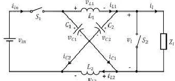
Z-source inverter has X-shaped impedance network on its DC side, which interfaces the source and inverter H-bridge. It facilitates both voltage-buck and boost capabilities. The impedance network co mposed of split inductors and two capacitors. The supply can be DC voltage source or DC current source or AC source. Z-source inverter can be of current Z-source type or voltage source type. Fig. 3 shows the general block d iagram of Z-Source inverter voltage.
Fig. 6 General Block Diagram of Z-Source Inverter
Z-Source inverter operation is controlled by multiple pulse width modulation. The output of the Z-Source inverter is controlled by using pulse width modulation, generated by comparing a triangular wave signal with an adjustable DC reference and hence the duty cycle of the switching pulse could be varied to synthesize the required conversion.
V. PHOTOVOLTA IC SYSTEM
A Photovoltaic (PV) system directly converts solar energy into electrical energy. The basic device of a PV system is the PV cell. Cells may be grouped to form arrays. The voltage and current available at the terminals of a PV device may directly feed small loads such as lighting systems and DC motors or connect to a grid by using proper energy conversion devices.
Fig.7. Block diagram representation of Photovoltaic system
This photovoltaic system consists of three main parts which are PV module, balance of system and load. The major balance of system co mponents in this systems are charger, battery and inverter. The Block diagram of the PV system is shown in Fig.7.
Fig.8. Practical PV device
A photovoltaic cell is basically a semiconductor diode whose p–n junction is exposed to light. Photovoltaic cells are made of several types of semiconductors using different manufacturing processes. The incidence of light on the cell generates charge carriers that originate an electric current if the cell is short circuited1
Fig.9. Characteristics I-V curve of the PV cell
VI. SIM ULA TION RESULTS
Fig.10 MAT LAB/Simulink model of three phase PV based Z-Source inverter
Fig.11 PV based Z-source DVR
Fig.12 MAT LAB/Simulink model of PV for Z-Source inverter
Fig.13 simulation waveform of pv output phase voltages
Fig.14 Simulated output wave forms of the source voltage due to the fault and the sag appeared on the source side from 0.1 sec to 0.5 sec dip
in magnitude of the source voltage.
Fig.15 Simulated output wave form of Load voltage
Even there is fault and sag appeared from the source side due the presence of the DVR load voltage is maintained constant
Fig.16 Simulated output wave form the Compensating voltages generated by the DVR.
F ig.18 Simulated output wave forms of the source voltage due to the fault
and the Swell appeared on the source side from 0.1 sec to 0.5 sec.
Fig.19 Simulated output wave form of Load voltage
Even there is fault and sag appeared from the source side due the presence of the DVR load voltage is maintained constant
Fig.20 Simulated output wave form the Compensating voltages generated by the DVR.
VII. CONCLUSION
Simulation of PV based Z-source DVR for Power
Quality Improvement is one of the techniques to
improve the power quality by using Z-source DVR.
In this paper the hysteresis voltage control technique
is used for controlling the dynamic voltage restorer
and generation of switching pulses for the inverter of
DVR. The Hysteretic Voltage Control can provide
fast transient response without additional loop
compensation, with the benefits of low cost and ease
of implementation. It is observed that throughout
fault condition the power factor at input side is
maintained unity and we adding the PV source in
input side. The total system output voltage is
maintained constant throughout the fault condition.
The simulation results show that the developed
control technique with proposed single phase DVR
is simple and efficient. These all results shown in
above
section
and
verified
by
using
MATLAB/SIMULINK software
REFERENCES
[1] N.G. Hingorani,“Introducing Custom Power in IEEE Spectrum,” 32p, pp. 4l-48, 1995.
[2] IEEE Std. 1159 – 1995, “Recommended Practice for Monitoring Electric Power Quality”.
[3] P. Boonchiam and N. Mithulananthan, “Understanding of Dynamic Voltage Restorers through MATLAB Simulation,” Thammasat Int. J. Sc. T ech., Vol. 11, No. 3, July-Sept 2006.
[4] J. G. Nielsen, M. Newman, H. Nielsen, and F. Blaabjerg, “Control and testing of a dynamic voltage restorer (DVR) at medium voltage level,” IEEE Trans. Power Electron. vol. 19, no. 3, p.806, May 2004. [5] A. Ghosh and G. Ledwich, “Power Quality Enhancement Using Custom Power Devices,” Kluwer Academic Publishers, 2002. [6] S. Chen, G. Joos, L. Lopes, and W. Guo,"A nonlinear control method of dynamic voltage restorers," in 2002 IEEE 33rd Annual Power Electronics Specialists Conference, 2002, pp. 88- 93.
[7] R. Buxton, "Protection from voltage dips with the dynamic voltage restorer," in IEE Half Day Colloquium on Dynamic Voltage Restorers Replacing T hose Missing Cycles, 1998, pp. 3/1- 3/6.
[8] H. Awad, J.Svensson, M. Bollen, “Mitigation of Unbalanced Voltage Dips Using Static Series Compensator”, IEEE Trans. On Power Elec., Vol. 19, No. 13, May 2004
[9] B. Singh, A. Adya, J. Gupta, “Power Quality Enhancement with DST AT COM for small Isolated Alternator feeding Distribution System” Power Electronics, And Drive System 2005, (PEDS 2005), Vol1., 16-18 Jan Pages: 274-279
[10] Nielsen, Newman, H. Nielsen, and F. Blaabjerg, “Control and testing of a dynamic voltage restorer (DVR) at medium voltage level,” IEEE T rans. Power Electronics. vol. 19, no. 3, pp. 806–813, May 2004. [11] J. G. Nielsen, “Design and Control of a Dynamic Voltage Restorer,” Ph.D. dissertation, Institute of Energy T echnology, Aalborg Univ., Aalborg, Denmark, 2002.
[12] Boonchiam P, and Mithulananthan N, “Understanding of Dynamic Voltage Restorers through MATLAB Simulation”. Thammasat Int. J. Sc. T ech., Vol. 11, No. 3, July-Sept 2006.
[13] Yusuf K: “Industrial power quality problems Electricity Distribution. IEEE Conf. Pub1 No. 482, Vol: 2, 18–21 June 2001 Pages: 5 pp. vo1.2.
[14] Fawzi AL Jowder, “Modeling and Simulation of Dynamic Voltage Restorer (DVR) Based on Hysteresis Voltage Control” The 33rd Annual Conference of the IEEE Industrial Electronics Society (IECON) Nov. 5-8, 2007, Taipei, Taiwan
[15] BenachaibaChellali, FERDI Brahim, “Voltage Quality Improvement Using DVR,” Electrical Power Quality and Utilizations, Journal Vol. XIV, No. 1, 2008
Author’s Profile:
DAMALL SAILAJA (ELECTRICA L POW ER SYSTEMS) Pursuing in Laqshya Institute of Technology sciences, Talikella(V), Khammam, Telangana, India. Email id: [email protected] m
Mr. T.HUSSAIN was born in India in the year of 1989.He received B.Tech degree in Electrical and Electronics Engineering in the year of 2010 & M.Tech PG in power Electronics & electric drives in the year of 2013 fro m JNTUH, Hyderabad. He is expert in Control Systems, Electrical circuits, Power s ystem Subjects. He is currently working as An Assistant Professor in EEE Department in Laqshya Institute of Technology and Sciences, Khammam, Telangana State, India.