Article
Assessment of the Makeability of T-welded Joints in 10 mm
Thick TMCP Steel Using Laser Beam
Jacek Górka
Department of Welding Engineering, Silesian University of Technology, Konarskiego 18A, 44-100 Gliwice, Poland; E-Mail: [email protected]; Tel.: +48-32-237-14-45; Fax: +48-32-237-1232
Abstract: The article presents tests aimed to verify the possibility of making T-joints in TMCP steel using laser. The tests involved the use of 10 mm thick high yield point steel S700MC obtained in an industrial manufacturing process. The joints made in the tests were single and double-sided. Subsequent non-destructive tests revealed that the joints obtained in the tests represented quality level B in accordance with PN-EN ISO 13919-1. Single-sided welding performed using the laser beam having a power of 11 kW enabled the obtainment of 8 mm deep penetration without visibly deforming the web of the joint. The double-sided welded joints were characterised by proper geometry and the presence of gas pores in the welds not compromising the requirements of quality level B (strict requirements). The weld structure was bainitic-ferritic. The weld hardness was by approximately 60 HV1 higher than that of the base material (280 HV1). The HAZ area was slightly softer than the base material. The tests of thin foils performed using a high-resolution scanning transmission electron microscope revealed that, during welding, an increase in the content of the base material in the weld was accompanied by an increase in contents of alloying microagents Ti and Nb, particularly near the fusion line. The above-named alloying microagents, in the form of fine-dispersive (Ti,Nb)(C,N) type precipitates, could reduce plastic properties of joints.
Keywords: laser beam, T-joints, weldability, TMCP steel
making of T-joints in thick sheets or plates (i.e. thicker than 4 mm). Presently, laser welding is used not only in the automotive industry but also in the shipbuilding and power engineering industrial sectors, where the making of thick T-joints is often required. The application of laser welding enables the obtainment of high-quality T-joints without the necessity of using filler metals, thus significantly lowering production costs and reducing welding strains in the aforesaid types of joints [25-29].
2. Experimental Section
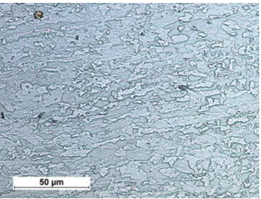
The tests aimed to verify the possibility of making welded joints in TMCP steels using the laser beam without the filler metal. The tests involved 10 mm thick high yield point steel S700MC obtained in the industrial manufacturing process. The chemical composition and properties of the steel are presented in Table 1, whereas the structure of the steel is presented in Figure 1.
Table 1. Actual chemical composition of 10 mm thick steel S700MC Contents of chemical elements, % by weight
C Mn Si S P Al Nb Ti V N* Ce
0.056 1.68 0.16 0.005 0.01 0.027 0.044 0.12 0.006 72 0.33 * - N: content in ppm; nitrogen was identified using the high-temperature extraction method
Mechanical properties Tensile strength Rm,
MPa
Yield point Re,
MPa
Elongation A5,
%
Toughness, J/cm2 (-20 C)
822 768 19 135
* - total content of Nb, V and Ti should amount to a maximum of 0.22%. ** Ce – carbon equivalent (22)
Fig. 1. Structure of bainitic-ferritic steel S700MC with visible effects of plastic deformation
2.1. Welding Process
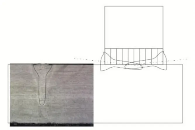
To adjust appropriate parameters enabling the obtainment of proper T-joints it was necessary to perform plate melting tests using various process parameters. An adopted melting rate of 2 m/min was constant, whereas parameters subjected to changes included the power of the laser beam and the position of the laser beam focus. The above-presented melting rate ensured that the efficiency of the laser welding of T-joints would be significantly higher than that obtained using arc methods when welding the same type of joints. It was noticed that the melting process was more stable (fewer spatters formed) when the laser beam focus penetrated the material subjected to welding (negative values of parameter f). Metallographic tests were used to determine the geometrical dimensions of the penetration run in relation to a given group of parameters. Afterwards, a graphic software programme was used to outline the fusion lines of the plate penetration run and to plot the above-named shape of the weld on the schematic diagram of the T-joint (Fig. 2). The foregoing combined with theoretical calculations of the focused beam divergence angle made it possible to adjust the power parameters of the double-sided welding of T-joints, an appropriate laser beam insertion angle and the position of the laser beam focus in relation to the interface of plates to be joined:
➢ laser beam insertion angle: α = 6°,
Fig. 2. Macrostructure of the plate penetration run performed using a laser beam power of 7 kW, the outlined fusion line and the outline of the penetration run plotted on the schematic diagram of the
T-joint
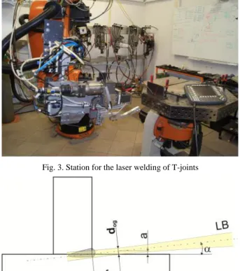
The melting and welding tests were performed using a TruLaser Robot 5120 robotic laser welding station (TRUMPF). The station included a TruDisk 12002 disc laser having a maximum power of 12 kW and provided with a working head attached to a six-axis KUKA KR30HA industrial robot (Fig. 3). The welding of the T-joints also involved the use of a D70 head (TRUMPF) connected to the disc laser using an optical fibre having a diameter of 0.3 mm. The welding head used in the tests was characterised by the following optical parameters:
➢ collimator lens focal length: fcol = 200 mm,
➢ focusing lens focal length: ffoc = 400 mm.
The above-presented optical parameters of the head and the use of the above-named optical fibre enabled the obtainment of the laser beam characterised by the following parameters (theoretical calculations):
➢ laser beam focus diameter dfoc = 0.6 [mm],
➢ Rayleigh length ZR = 7.5 [mm],
➢ focused laser beam divergence angle Θf = 4.6 [deg.],
➢ laser beam quality parameter BPP = 12 [mm·mrad].
Fig. 3. Station for the laser welding of T-joints
Fig. 4. Schematic diagrams of primary geometrical correlations between the position of the laser beam focus having diameter dfoc and the interface (line) of the plates in the welded joint area
Fig. 5. Maximum penetration during single-sided welding
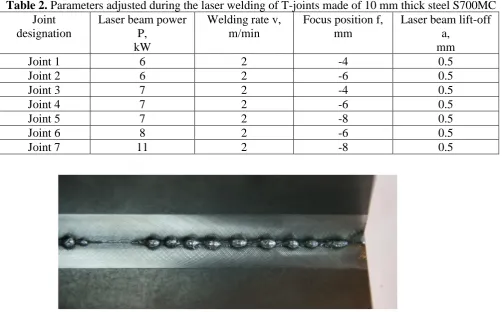
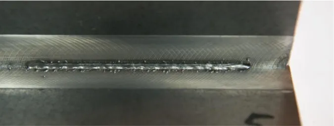
At the same time, on the weld face side it was possible to observe the incompletely filled groove along the entire length of the joint (Fig. 7). Because of the very narrow window of stable single-sided welding parameters it was ascertained that an alternative (competitive) solution could include double-sided welding ensuring the formation of the proper weld face and providing significant flexibility as regards changes in welding process parameters (Fig. 8). The welding process parameters in relation to selected joints are presented in Table 2.
Table 2. Parameters adjusted during the laser welding of T-joints made of 10 mm thick steel S700MC Joint
designation
Laser beam power P,
kW
Welding rate v, m/min
Focus position f, mm
Laser beam lift-off a,
mm
Joint 1 6 2 -4 0.5
Joint 2 6 2 -6 0.5
Joint 3 7 2 -4 0.5
Joint 4 7 2 -6 0.5
Joint 5 7 2 -8 0.5
Joint 6 8 2 -6 0.5
Joint 7 11 2 -8 0.5
Fig. 7. Single-sided T-joint with the incompletely filled groove
Fig. 8. Double-sided T-joint with the proper weld face
2.2. Tests of Welded Joints
The test welded joints were subjected to visual tests following the requirements of PN-EN ISO 17637:2011. Afterwards, the joints were subjected to the following destructive tests:
➢ macroscopic metallographic tests involving the use of an Olympus SZX9 light stereoscopic microscope; the test specimens were etched using Adler’s reagent,
➢ microscopic metallographic tests involving the use of a NIKON ECLIPSE MA100 light microscope; the test specimens were etched using Nital,
➢ quantitative tests concerning contents of microagents hardening steel S700MC, performed using a JXA-8230 electron microprobe X-ray analyser (JEOL) and wavelength dispersion spectroscopy (WDS),
➢ tests of thin foils using a Titan 80-300 kV high-resolution scanning transmission electron microscope (HR S/TEM) (FEI) equipped with an XFEG electron gun featuring Schottky field emission of enhanced brightness,
➢ phase analysis-related X-ray tests performed using an X’Pert PRO diffractometer and an X’Celerator strip detector,
➢ assessment of a welding imperfection (gas pores), following the requirements of PN-EN ISO 13919-1:2002.
3. Results and Discussion
Fig. 9. Macrostructure of the T-joint in order 1-7, (Table 2)
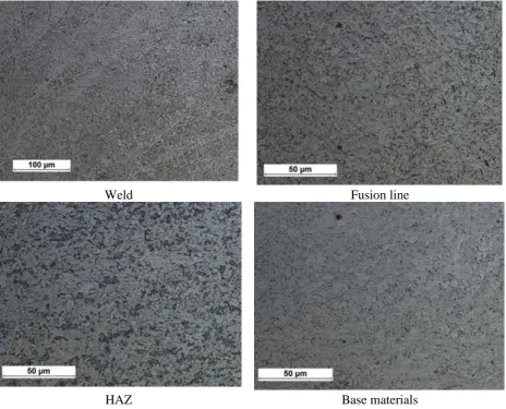
The microscopic tests concerning the weld area revealed the bainitic-ferritic structure. The HAZ area did not reveal any significant changes in the grain size in relation to the base material. The foregoing was related to a very low heat input to the welded joint area during the laser welding process (Fig. 10).
Weld Fusion line
HAZ Base materials
The microscopic tests revealed the presence of gas pores in the welded joints. The formation of the above-named gas pores could be ascribed to the fast crystallisation of the liquid metal pool triggered by very high welding rates responsible for the impeded release of gases from the weld zone. The gas pores could form as a result of the confinement of gases dissolved in the metal or as a result of the evaporation of alloying elements or impurities, if any, located on the surface of the interface of the joined sheets. The identification of the significance of the above-named imperfection required the performance of verification tests based on the PN-EN ISO 13919-1:2002 standard (Table 3). The welded joint subjected to the verification of quality, i.e. joint no. 3, was characterised by the presence of the greatest gas pore (Fig. 11).
Fig. 11. Size of the gas pore in joint no. 3
Table. 3. Ultimate limit sizes of welding imperfections in the form of gas pores in accordance with PN-EN ISO 13919-1:2002
Ultimate limit sizes of welding imperfections in relation to quality levels Lenient requirements
D
Medium requirements C
Strict requirements B
l or h ≤ 0.5 t or 5 mm; lower value applies,
f ≤ 6 %
l or h ≤ 0.4 t or 3 mm; lower value applies,
f ≤ 2 %
l or h ≤ 0.3 t or 2 mm; lower value applies,
f ≤ 0.7 %
Key:
l – length of a welding imperfection (measured in any direction), h – dimension of a welding imperfection (height, width),
Satisfied requirements of quality level B
The greatest welding imperfection of the T-joints satisfied the requirements of quality level B, therefore the
remaining joints also satisfied the requirements of quality level B.
The X-ray phase analysis revealed that the base material and the weld made using the laser beam were entirely composed of the ferritic phase (Fig. 12).
Fig. 12. XRD pattern of the weld of the laser-welded joint made of steel S700MC
not dissolved entirely in the liquid metal pool. The excessively high concentration of hardening phases in the fusion area could have a highly adverse effect on the plastic properties of the weld.
1 3 5 7 9 11 13 15 17 19 21 23 25 27 29 31
Place of measurement 0,00 0,02 0,04 0,06 0,08 0,10 0,12 0,14 0,16 0,18 0,20 Co n cent ra tio n o f th e e lem en t w t, %
Distribution of Nb Distribution of Ti Area fusion
HAZ Weld
Fig. 13. Distribution of Ti and Nb in the fusion area of the laser-welded joint made of steel S700MC
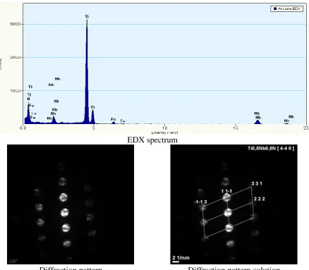
The significant content of hardening phases in the weld during cooling led to the significant precipitation hardening through fine-dispersive (Ti,Nb)(C,N) type precipitates (of several nm in size), precipitated near greater (Ti,Nb)N particles (100 nm in size) (Fig. 14), which reduced the plastic properties of the welds.
EDX spectrum
Diffraction pattern Diffraction pattern solution
Fig. 14. Precipitate of the (Ti,Nb)N nitride along with the fine spherical hardening precipitates in the weld of steel S700MC, made using the laser beam
0 1 2 3 4 5 6 7 8 9
Welded joint number
320 325 330 335 340 345 350 355 360 H a rd n e s s H V 1
8 - base material
Fig. 15. Averaged hardness in the weld area of the T-joints
0 1 2 3 4 5 6 7 8 9
Welded joint number
250 255 260 265 270 275 280 285 290 H a rd n e s s H V 1
8- base material
Fig. 16. Averaged hardness in the HAZ area of the T-joints 4. Conclusions
hardness of approximately 350 HV1. In turn, the HAZ area was characterised by the slight growth of grains and the partial loss of properties previously obtained in the thermo-mechanical control process. The foregoing resulted in the formation of a zone softer than the base material (260 HV1). The above-named slight softening did not reduce the mechanical properties of the joints. During laser welding performed without the use of the filler metal the contents of alloying microagents (Ti and Nb) in the weld were the same as those in the base material. The significant content of hardening phases in the weld during cooling resulted in the significant precipitation hardening by fine-dispersive (Ti,Nb)(C,N) type precipitates, which could lead to the deterioration of the plastic properties of the welds. The above-named phenomenon can be reduced by performing the laser welding process involving the use of the filler metal or by using the hybrid laser arc welding process (HLAW), i.e. laser beam + electric arc). The aforesaid solution could reduce the contents of alloying microagents (Ti and Nb) in the weld, yet it would entail higher production costs.
Acknowledgements
The publication of the study was co-funded using the statutory subsidy of the Faculty of Mechanical Engineering of the Silesian University of Technology in 2018.
References
1. A. Kurc-Lisiecka, A. Lisiecki, Laser welding of the new grade of advanced high-strength steel Domex 960. Materiali in tehnologije/Materials and technology 51 (2017) 2, 199–204. doi:10.17222/mit.2015.158.
2. A. Kurc-Lisiecka, J. Piwnik, A. Lisiecki, Laser welding of new grade of advanced high strength steel STRENX 1100 MC. Arch. Metall. Mater. Vol. 62 (2017), No 3, p. 1651-1657 DOI: 10.1515/amm-2017-0253
3. Górka J., Janicki D., Fidali M., Jamrozik W.: Thermographic Assessment of the HAZ Properties and Structure of Thermomechanically Treated Steel, Int J Thermophys (2017) 38:183 DOI 10.1007/s10765-017-2320-9.
5. Górka J.: Welding Thermal Cycle-Triggered Precipitation Processes in Steel S700MC Subjected to the Thermo-Mechanical Control Processing, Arch. Metall. Mater. 62 (2017), 1, 331-336, DOI: 10.1515/amm-2017-0048.
6. Górka J., Stano S.:, The structure and properties of filler metal-free laser beam welded joints in steel S700MC subjected to TMCP, Proc. SPIE 10159, Laser Technology 2016: Progress and Applications of Lasers, 101590K (December 8, 2016); doi:10.1117/12.2256176, p. 183-190. 7. Grajcar A., Różański M., Kamińska M., Grzegorczyk B.: Effect of gas atmosphere on the
non-metallic inclusions in laser-welded TRIP steel with Al and Si additions, Materiali in Tehnologije 50, No. 6, 2016, pp. 945-950.
8. A. Kurc-Lisiecka, A. Lisiecki, Laser welding of the new grade of advanced high-strength steel Domex 960. Materiali in tehnologije/Materials and technology 51 (2017) 2, 199–204. doi:10.17222/mit.2015.158.
9. Portera, D., Laukkanenb A., Nevasmaab P., Rahkab K., Wallin K.: Performance of TMCP steel with respect to mechanical properties after cold forming and post-forming heat treatment, International Journal of Pressure Vessels and Piping, vol. 81/2004, pp. 867-877.
10. Yurioka M.: TMCP steel and their welding, Welding in the World, vol. 35, 6/1995, pp. 375-390. 11. Bajić N., Šijački-Žeravčić V., Rakin M., Kovačević K.: Effect of the welding mode and filler
content on the structure of microalloyed Nb/Ti steel weldments. Materials Science, vol. 46, Issue 1, September 2010, pp. 124-133.
12. Kim Y., Kwon J., Lee H., Jang W.: Effect of microstructure on fatigue crack propagation and S–N fatigue behaviours of TMCP steels with yield strengths of approximately 450 MPa, The Minerals, Metals & Materials Society and ASM International 2010, pp. 986-999.
13. Altuna M.A., Iza-Mendia A., Guitierrez I.: Precipitation strengthening by formation in ferrite of Nb carbides, 3rd International Conference on Thermomechanical Processing of Steels – TMP’2008, Padua 2008, pp. 1-12.
14. Hashimoto S., Ikeda S., Sugimoto K., Miyake S.: Effects of Nb and Mo addition to 0,2%C-1,5%Mn steel on mechanical properties of hot rolled TRIP-aided steel sheets, ISIJ International, vol. 44, No. 9/2004, pp. 1590-1598.
15. Wang X.D., Huang B.X., Wang L., Rong Y.H.: Microstructure and mechanical properties of microalloyed high-strength transformation-induced plasticity steels, Metallurgical and materials Transactions A, vol. 39A, No. 1, 2008, pp. 1-7.
16. Timokhaina I.B., Hodgson P.D., Pereloma E.V.: Effect of microstructure on the stability of retained austenite in transformation-induced-plasticity steels, Metallurgical and materials Transactions A, vol. 35A, No. 1, 2004, pp. 2331-2341.
17. Opiela M.: Elaboration of thermomechanical treatment conditions of Ti-V and Ti-Nb-V microalloyed forging steels, Archives of Metallurgy and Materials, vol. 59, issue 3 (2014) p.1181-1188.
18. Grajcar A., Różański M., Kamińska M., Grzegorczyk B.: Effect of gas atmosphere on the non-metallic inclusions in laser-welded TRIP steel with Al and Si additions, Materiali in Tehnologije 50, No. 6, 2016, pp. 945-950.
Transactions A, February 1991, vol. 22, Issue 2, pp. 489-498.
23. Rodriguesa P., Perelomab E., Santos C.: Mechanical properties of an HSLA bainitic steel subjected to controlled rolling with accelerated cooling, Materials Science and Engineering: A, vol. 283, Issue 1–2, 15 May 2000, pp. 136-143.
24. Bhadeshia H.K.: Bainite in Steels - 2nd Edition, Cambridge: Institute of Materials, Minerals and Mining, 2001, pp. 265-268.
25.Rajashekhar S., Pal M., “Weldability of advanced high strength steels using an Yb:YAG disk laser,” J. Mater. Process. Tech., Papers 211, 1888-1897 (2011).
26.Ming G., Xiaoyan Z., Qianwu H., Jun Y., “Laser-TIG hybrid welding of ultra-fine grained steel,” J. Mat. Proc. Tech., 209, 785-791 (2009).
27.Lisiecki A., “Effect of heat input during Disk laser bead-on-plate welding of thermomechanically rolled steel on penetration characteristics and porosity formation in the weld metal,” Arch. Metall. Mater., 61 (1), 93–102 (2016).
28.Grajcar A., Różański M., Stano S., Kowalski A., Grzegorczyk B., “Effect of Heat Input on Microstructure and Hardness Distribution of Laser Welded Si-Al TRIP-Type Steel,” Adv. in Mat. Sci. and Eng., 2014.