IJEDR1402105
International Journal of Engineering Development and Research (www.ijedr.org)1947
Design of Planar Archimedean Spiral Antenna for
Wi-Max Using Different Materials
1
Sanket N. Patel,
2Vivek R.
1Student, 2Assistant Professor1Department of Electronics & Communication, 1
Marwadi education foundation for PG studies, Rajkot, India
1[email protected], 1[email protected]
--- Abstract– The purpose of this paper is to study and analysis of planar Archimedean spiral antenna using different substrate materials. The designed antenna is for Wi-Max application and the optimum output is taken at 3.65 GHz frequency. The simulation results are done in HFSS v13 software and the dielectric materials used are FR4, Rogers RT/ duroid 5880 (tm), Teflon (tm).
Keywords - HFSS, Spiral Antenna, Wi-Max
---
I.INTRODUCTION
There are many research areas but wireless technology is one of the main areas of research for the communication systems and a study of communication systems understanding of the operation and fabrication of antennas is necessary. Antenna is the structure associated with the region of transition between a guided wave and a “free space” wave, or vice versa [1]. The spiral antenna is a wideband antenna with low profile and circular polarization. The frequency band of a spiral antenna depends on the physical dimension of the antenna. The planar Archimedean spiral antenna is the class of frequency independent antenna [2]. Frequency independent antennas are design to minimize finite lengths and maximize angular dependence. The design and simulations are carried out in HFSS v13 software. In this paper the planar Archimedean spiral antenna is designed for the Wi-Max application and also the comparative analysis of designed antenna with different materials.
II.ANTENNADESIGN,GEOMETRY&CONFIGURATION
The Archimedean spiral increases uniformly with the angle.
r = aϕ + b (2.1)
Where, r- distance from the origin, b-initial point and a-growth rate. The growing spiral arm separate the currents. A spiral radiates RHC (right hand side circular) polarization and LHC (left hand side circular) Polarization.
Fig.2.1 Archimedean spiral antenna [3]
Here arm of an Archimedean spiral is linearly proportional to the angle ϕ and the relationship is
& (2.2)
Where is the inner radius of spiral and is the proportionality constant and getting from,
(2.3)
IJEDR1402105
International Journal of Engineering Development and Research (www.ijedr.org)1948
(2.4)
Where, is the outer radius of spiral and N is the number of turns. For the self-complementary antenna spacing or width can be written as,
(2.5)
For probe feeding, the relation between strip widths to radius of wire can be found by,
(2.6)
Where, a is wire radius and w is width of each spiral arm.
The important parameter is setting the value of inner radius , for the frequency independent behavior of spiral antenna inner radius is equal to the strip width or spacing between turns so we get
(2.7)
The below is the HFSS design of the Planar Archimedean Spiral Antenna.
Fig.2.2 Planar Archimedean Spiral antenna (1.5 turn) HFSS design.
PARAMETERS VALUES
Frequency Wi-Max band(3.65 GHz)
Substrate material FR4-epoxy
Substrate dielectric constant 4.4
Substrate height 1.6 mm
No of turns 1.5
Inner radius 0.0001 mm
No of arms 2
Offset angle 900
Table.2.1. Design Specifications
Here feeding is given by lumped port. Width of the feed is 5mm and the length of the feed line is 22mm. The substrate materials are FR4-epoxy, RT Duroid and Teflon with dielectric constant 4.4, 2.2 and 2.1 respectively. The spiral is made of copper. Air box size is 110x110x50 mm.
IJEDR1402105
International Journal of Engineering Development and Research (www.ijedr.org)1949
(a) (b)
(c)
Fig.3.1 Return loss of Planar Archimedean Spiral Antenna (a) Using FR4 (b) Using RT Duroid (c) Using Teflon
(a) (b)
(c)
Fig.3.2 VSWR of Planar Archimedean Spiral Antenna (a) Using FR4 (b) Using RT Duroid (c) Using Teflon
IJEDR1402105
International Journal of Engineering Development and Research (www.ijedr.org)1950
Fig.3.3 Gain of Planar Archimedean Spiral Antenna (a) Using FR4 (b) Using RT Duroid (c) Using Teflon
(a) (b) (c)
Fig.3.4 Gain radiation pattern of Planar Archimedean Spiral Antenna (a) Using FR4 (b) Using RT Duroid (c) Using Teflon
(a) (b) (c)
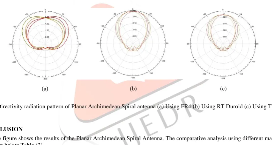
Fig.3.5 Directivity radiation pattern of Planar Archimedean Spiral antenna (a) Using FR4 (b) Using RT Duroid (c) Using Teflon
IV.CONCLUSION
The above figure shows the results of the Planar Archimedean Spiral Antenna. The comparative analysis using different materials is shown in below Table (2).
PARAMETERS MATERIALS
FR4 RT
Duroid
Teflon
Return Loss -13.9045 -1.1062 -2.3656
VSWR 1.5054 15.7258 7.3887
Gain -7.8096 3.0608 3.1823
Directivity -0.9280 5.4352 5.5833 Radiation
Efficiency
2.3864 3.4208 3.5535
Table 4.1 Result Analysis
IJEDR1402105
International Journal of Engineering Development and Research (www.ijedr.org)1951
REFERENCES[1] Constantine A. Balanis, Antenna Theory Analysis and Design, third edition, A John Wiley & sons , INC, Publications.2005
[2] Thaysen, J.; Jakobsen, Kaj Bjarne; Appel-Hansen, J. /A Logarithmic Spiral Antenna for 0.4 to 3.8 GHz. In: Applied Microwave & Wireless, Vol. 13, No. 2, 2001, p. 32-45.
[3] Richard C. Johnson, Antenna Engineering Handbook, third edition, Mc-Graw Hill publishing company
[4] Changjie Sun, Guobin Wan, Zhang Hu, and Xin Ma School of Electronic and Information, Northwestern Polytechnical University, Xi'an 710129, China “Design and Simulation of Planar Archimedean Spiral Antenna” Progress In Electromagnetics Research Symposium Proceedings, Xi'an, China, March 22-26, 2010
[5] Aoad, A.; Korkmaz, E., "Simulation of a rectangular spiral shaped microstrip patch antenna," General Assembly and Scientific Symposium, 2011 XXXth URSI , vol., no., pp.1,3, 13-20 Aug. 2011
[6] Paulino, N.; Rebelo, H.; Pires, F.; Ventim Neves, I.; Goes, J.; Steiger-Garcao, A., "Design of a spiral-mode microstrip antenna and matching circuitry for ultra-wide band receivers," Circuits and Systems, 2002. ISCAS 2002. IEEE International Symposium on , vol.3, no., pp.875,878, 2002
[7] A. A. Jamali1, A. Gaafar1, and A. A. Abd Elaziz2 “Finite Different Ground Shapes Printed Spiral Antennas for Multi Wide Band Applications Using PPPC Feeding Scheme” PIERS Proceedings, Suzhou, China, September 12-16, 2011 [8] Dinisio Raony Ribeiro, Leonardo Augusto de Santana, Marlen Carneiro Alves, Jose Felipe Almeida, “Spiral Microstrip
Antenna” Carlos Leonidas da S.S. Sobrinho Depto of Elect. and Comp. Eng., Federal University of Para (UFPA), Belem, PA, Brazil.
[9] John Denial Krauss, Antenna and Wave propagation, 2ndedition, Mc-Graw Hill Publication