Volume 2009, Article ID 630964,14pages doi:10.1155/2009/630964
Research Article
A Coordinated Resource Allocation Algorithm for
Infrastructure-Based Relay Networks
Christian M¨
uller,
1Anja Klein,
1and Bernhard Raaf
21Communications Engineering Lab, Technische Universit¨at Darmstadt, Merckstr 25, 64283 Darmstadt, Germany
2Nokia Siemens Networks GmbH & Co. KG, St. Martin-Strasse 76, 81541 M¨unchen, Germany
Correspondence should be addressed to Christian M¨uller,[email protected]
Received 30 January 2008; Revised 15 April 2008; Accepted 3 August 2008
Recommended by Petar Popovski
A resource allocation algorithm for orthogonal frequency division multiple access-based and infrastructure-based relay networks is introduced in this paper. The algorithm is applied in the downlink of a single cell. Channel state information is exploited at the transmitting base station (BS) and at the transmitting relay stations (RSs). The algorithm coordinates the allocation of subcarriers, bits, and power distributed over the BS and RSs. The goal of the resource allocation algorithm is that the sum rate in a cell is maximized. Simultaneously, each subscriber station (SS) achieves a requested data rate called minimum data rate, and a tolerated bit error probability is ensured on each link. Simulation results show that a sum rate in a cell is achieved which is near to an upper bound introduced in the paper. Even if the sum of the minimum data rates of all SSs is large, the proposed algorithm offers the minimum data rate nearly as reliable as the upper bound. Additionally, simulation results show that the proposed algorithm achieves a superior sum rate compared to the sum rate of other resource allocation algorithms.
Copyright © 2009 Christian M¨uller et al. This is an open access article distributed under the Creative Commons Attribution License, which permits unrestricted use, distribution, and reproduction in any medium, provided the original work is properly cited.
1. Introduction
Two promising techniques are expected in future cellular net-works: transmissions using a fixed relay station (RS) [1] and orthogonal frequency division multiple access (OFDMA) [2].
Transmissions using an RS bring various benefits in future cellular networks: such a type of transmission enables a coverage extension of a base station (BS), capacity enhance-ment in a cell or cost reduction compared to conventional cellular networks [1, 3, 4]. A subscriber station (SS) is connected either directly to a BS or via an RS which is connected to a BS. Like the BS, the RSs are part of the infrastructure. This kind of network is called infrastructure-based relay network.
OFDMA is a multiple access scheme applied in various wireless systems like IEEE 802.11 or IEEE 802.16 and is a promising candidate for future cellular networks, for example, accepted for 3GPP LTE [5] and in the European Union research project WINNER [6]. An advantage of OFDMA is the flexibility concerning the allocation of the
resources power and subcarriers in a multiuser environment [7,8]. If the channel state information (CSI) is known at the transmitter, OFDMA enables an adaptive allocation of the resources to the links of a network taking into account quality of service (QoS) parameters requested by higher layer protocols like a requested data rate or a tolerated bit error probability. A cross-layer design of the allocation of subcarriers at the medium access control layer and a suitable choice of the transmit power and the used modulation scheme on the physical layer improve the performance of an OFDMA system [2]. Hence, various cross-layer methods exist for OFDMA systems dealing with the allocation of resources, for instance, given in [2,9–12]. However, these methods are limited to conventional cellular networks in which no RSs are deployed.
methods for the adaptive allocation of resources in a cell of a conventional cellular network, the allocation in a cell of a relay network leads to several new challenging problems. The CSI must be obtained by the BS and the RSs. If an RS knows the CSI of its served RS-to-SS links, it is not ensured that the BS is aware of this CSI. In comparison to a cell of a conventional network, the CSI of all links in the downlink of a cell can be distributed over several transmitters. The allocation of resources must be coordinated between the BS and the RSs. For instance, the allocation must be coordinated to balance the data rate on a BS-to-RS link and on the corresponding RS-to-SS links. QoS requirements must be fulfilled for all connections demanding a coordination such that the QoS requirements are fullfilled on the BS-to-RS links and RS-to-SS links for the connections of the SSs assigned to a RS. Coordination always means a signaling overhead which degrades the efficient use of resources. The allocation of resources must take into account that the costs of an RS are kept low in order to exploit the advantages of a relay network in terms of costs [4,13].
In literature, a few methods exist which deal with the allocation of resources in relay networks using OFDMA. In [14], a method is proposed which aims at maximizing the sum rate in a cell by adaptive subcarrier allocation and adaptive power loading on the multiple links in a cell of a relay network. In [15], a resource allocation method for a relay network is presented which minimizes the transmit power of the BS and the RSs subject to the constraint that each SS achieves a minimum data rate. The methods presented in [14,15] require the short-term CSI of all links at a central point in the cell, for example, the BS. Since the short-term CSI of all RS-to-SS link must be reported to the BS, a high signaling overhead is expected for these methods. In [16], a resource allocation method is presented for mesh networks in which typically an RS is not part of the infrastructure but SSs act as RSs. The allocation of resources is executed over the transmitters. Based on long-term CSI and based on knowledge of the traffic per transmitter, a central unit, for example, a BS, allocates the number of subcarriers to the links. Each transmitter performs the power allocation to its subcarriers. The short-term CSI of all links is not required at a central point which is a promising approach to reduce signaling overhead. The resource allocation method is proved to be proportional fair [17]. Since an RS receives and transmits simultaneously, strong intercarrier interference is expected at an RS.
In [18], various resource allocation methods are pre-sented for relay networks aiming at a reduction of the signaling overhead between an RS and a BS. In all methods, the CSI of all subcarriers and of all RS-to-SS links is not forwarded to the BS. Instead, the RS allocates subcarriers to its RS-to-SS links and requests packets from the BS which will be transmitted over the BS-to-RS link. The methods presented in [18] allocate subcarriers and choose a modulation and coding scheme according to a proportional fair metric. Since the methods given in [16,18] are based on the proportional fair criterion, a fair distribution of data rates related to a requested data rate is achieved but the fairness is paid by a reduction of the sum rate in the cell.
In [19], subcarriers and a modulation and coding scheme are allocated in order to maximize the sum of data rates. As in [18], the RS requests packets from the BS but QoS requirements are not considered.
In this paper, a novel resource allocation algorithm is introduced for the downlink in a cell of an OFDMA-based relay network. The goal of the resource allocation algorithm is that the sum rate in a cell is maximized subjected to the consideration of two QoS requirements of each connection. The first QoS requirement is that a requested data rate called minimum data rate is achieved. The second one is that a tolerated bit error probability is ensured. The goal and the constraints of the resource allocation algorithm are chosen since they promise a good trade-off between fairness and system performance as introduced in [20]. On the one hand, a maximization of the sum rate in a cell not taking into account QoS requirements leads to an unfair distribution of the data rates among the SSs. On the other hand, a maximization of the sum rate taking into account a strict fairness criterion, for example, the proportional fair criterion, leads to a reduction of the sum rate in the cell. The proposed resource allocation algorithm operates distributed over the BS and RSs in a cell to overcome the drawback of high signaling. The transmissions of the BS and the RSs are separated in time domain so that an RS does not receive and transmit simultaneously. The BS and the RSs are allocated adaptively slots of a frame by applying the algorithm. The allocation of the slots to the BS and RSs depends on the CSI and on the offered data rate. The BS and the RSs allocate subcarriers to their served links using the CSI. The power allocated to a subcarrier by the BS or an RS is allocated such that a chosen number of bits is successfully transmitted according to a tolerated bit error probability. The allocation of subcarriers, bits, and power is described by a linear integer programs. Since these programs are NP-hard, suboptimal algorithms are proposed to solve these problems enabling a near optimum solution at low complexity.
The outline of the remainder of the paper is as follows. In Section 2, a system model is introduced. In the system model, two types of CSI are defined and the assumptions which transmitter knows the CSI of a link in a cell are given. Section 3 presents the novel coordinated resource allocation algorithm. The presented algorithm demands that two different subcarrier, bit, and power allocation problems described as linear integer programs are solved at the BS and at the RSs. Algorithms solving these problems are presented in Section 4. In Section 5, an evaluation of the presented algorithm is given by a comparison to other algorithms using simulation results. Conclusions are drawn inSection 6.
2. System Model
NRS+ 1≤l≤NSS+NRS. An RS can be a transmitter or a receiver, but it cannot transmit and receive simultaneously. The receivers served by a transmitter t are grouped in the set Lt. The SSs assigned to a BS use a direct connection consisting of one link. These SSs are grouped in the set
L1hop. The SSs assigned to an RS use a two-hop connection consisting of two links and are given by the setL2hop.
A frame-based OFDMA transmission is considered. A frame consists ofSslots. A slot is defined as a single OFDM symbol in the rest of this paper. The transmissions of the BS and the RSs are separated by TDMA. Within a frame, a number of consecutive slots called subframe is allocated to each transmitter. The first subframe is used by the BS and the others by the RSs. Either the BS or an RS of the cell transmits during a subframe. The BS and an RS or two RSs do not transmit simultaneously. On the one hand, simultaneous transmissions within a cell can increase the sum rate in the cell if the reuse distance is sufficiently large. On the other hand, if the reuse distance is small, cochannel interference reduces the sum rate. A transmission in which the BS and RSs send in a consecutive order is inefficient if a large number of transmitters per cell exist. Thus, the algorithm proposed in this paper is more suitable to deployments considering a small number of RSs per BS and to scenarios in which a large reuse distance in a cell is not given. Frequencies are reused in such a network by transmitters in different cells. Within a subframe, the transmissions of different links are separated by FDMA, that is, each subcarrier is assigned to one link uniquely. The total number of subcarriers in the system is
NSC. The subcarrier spacing is chosen such that the channel can be considered as flat for each subcarrier.
In this paper, two types of CSI are considered. The first type is called short-term CSI and is defined as the ratio of the squared absolute value of the instantaneous channel coefficient represented byα2
t,l,nand the noise powerσt2,l,non a link (t,l) and on a subcarriern, wheren = 1, 2,. . .,NSC. Cochannel interference created in other cells is modeled by a Gaussian process and included in the noise power σt2,l,n. The short-term CSI is affected by path loss, shadowing, and fast fading effects. It is assumed that the short-term CSI is not time varying for the duration of a frame. This is an appropriate assumption if the duration of a frame is smaller than the coherence time of the channel. The second type of CSI is called long-term CSI and is defined as the expectation value of the short-term CSI of a link, where the expectation value is taken over all subcarriers and a long time period compared to the coherence time. The long-term CSI is affected by the path loss and shadowing effects. Assuming a time invariant channel, the long-term CSI is given by
En{α2
t,l,n/σt2,l,n}, whereEn{·}represents the expectation value taken over the subcarriers.
If a transmitter knows the short-term CSI of the links to the assigned stations, adaptive subcarrier, bit and power allocation is possible. If only long-term CSI is known, subcarriers must be allocated to links and the bits and the power must be loaded on a subcarrier without exploiting knowledge about the channels of single subcarriers. Com-pared to an allocation based on long-term CSI, a gain in terms of data rate is expected for an adaptive allocation
taking into account short-term CSI [2, 9]. The price to be paid for this gain is that the short-term CSI must be obtained and be reported to a transmitter. In a time division duplex (TDD) system, the BS or an RS can estimate the short-term CSI of a link to an assigned station from the received uplink signal. In a frequency division duplex (FDD) system, the downlink receiver must report the short-term CSI to the BS or an RS leading to a signaling overhead. In order to reduce signaling, adjacent subcarriers which are affected by a strongly correlated channel can be grouped in a resource block [21]. The channel of a resource block can be represented by the channel of a single subcarrier of the resource block. For simplicity, only single subcarriers are considered in this paper instead of resource blocks.
If the BS will have short-term CSI about the RS-to-SS links, the RS must forward the short-term CSI about the RS-to-SS links to the BS leading to a signaling overhead of
NSC parameters per RS-to-SS link. In this paper, the BS is assumed to know the short-term CSI on all subcarriersnof all links (0,l) and the long-term CSI of all links (0,l) for which l ∈ L0. An RS t knows the short-term CSI on all subcarriersnof all links (t,l) and the long-term CSI of all links (t,l) for whichl ∈ Lt. The BS has no CSI about the RS-to-SS links to avoid a large signaling overhead.
Different modulation and coding schemes can be applied on a subcarrier. A 4-QAM, 16-QAM, and 64-QAM without an error control code are considered in this paper. The number of bits loaded on a subcarrier is c. The possible values of c are given as the elements of a set called
D. Considering that also zero bits can be allocated to a subcarrier, the set is given byD = {0, 2, 4, 6}according to the modulation schemes. The function ft,l,n(c) describes the required receive power on a subcarrier nfor the reception ofcbits per symbol according to a noise powerσ2
t,l,nand a maximally tolerated bit error probabilityρt,l on link (t,l). The function ft,l,n(c) [7] is given by
ft,l,n(c)=
2c−1σt2,l,n 3
Q−1
ρ
t,l 4
2
, (1)
whereQ−1(·) denotes the inverse error function. The three modulation schemes are used here for simplicity. Any other modulation and coding scheme is also applicable by replacing (1) if the transmitter knows an appropriate mapping of the number of bits, the bit error probability, and the noise power to the required receive power.
The transmit power which is required in order not to exceedρt,lon subcarriernis given by
Pt,l,n= ft,l,n (c)
α2t,l,n
. (2)
An indicator variableut,l,n,cis introduced which describes if a subcarriernis allocated to a link (t,l) and if subcarriernis loaded withcbits. The indicator variable is defined as
ut,l,n,c=
⎧ ⎪ ⎪ ⎨ ⎪ ⎪ ⎩
1 if cbits are mapped on subcarriern
allocated to link (t,l), 0 otherwise.
The transmit power of a transmittertis given by
Pt=
l∈Lt
NSC
n=1
c∈D ft,l,n(c)
α2
t,l,n
ut,l,n,c. (4)
Each SS will achieve its minimum data rate. The minimum data rate Rlof a receiverlgiven in bits per frame is trans-formed to the number of bits which must be transmitted in a slot assuming a subframe sizeSt. The transformed minimum data rate of a receiverlis represented byR(St)
l and given by
R(St)
l =
S StRl.
(5)
The data rate of a link (t,l) served in a subframe is calculated by
rt,l= NSC n=1
c∈D
cut,l,n,c (6)
and is given in bits per slot.
An unlimited amount of data for each SS is assumed to be available at the BS. The RS can only forward data received by the BS. Data received by an RS must be forwarded within the same frame to the SS. Data which is not forwarded in the same frame is assumed to be lost.
3. Coordinated Resource Allocation Algorithm
In this section, the allocation of slots to the BS and RSs, the assignment of subcarriers to a link and loading power and bits on a subcarrier are defined in an algorithm called coordinated resource allocation algorithm. The algorithm takes into account that the CSI of all links in the cell is distributed over the BS and the RSs and is not known at a central unit like the BS. Since reporting the short-term CSI to a central unit is inefficient, it is concluded to determine the allocation of resources in the coordinated resource allocation algorithm partly at the BS and partly at the RS. The aim of the coordinated resource allocation algorithm is to maximize the sum rate in a cell. The allocation of resources is subject to the following constraints.
(i) Each SS requests a data rate which must be served to the SS. This data rate is given in bits per frame and is called minimum data rate.
(ii) The data rate is provided with a tolerated bit error probability.
(iii) In a subframe, each subcarrier is allocated exclusively to one link in the cell.
(iv) The transmit powers of the BS and RSs are limited.
The fundamental idea of the coordinated resource allo-cation algorithm is as follows. First of all, the slots are split between the transmitters such that all connections fulfill their minimum data rate. If slots are not required to offer the minimum data rate, remaining slots are allocated to the transmitter which serves the connection which is expected to
achieve the highest data rate. This connection is called best connection. The best connection is allocated as much slots, subcarriers, and power as possible.
A flow chart of the coordinated resource allocation algorithm is illustrated inFigure 1. On the left-hand side, the operations are given which are executed by each RS in the cell. An RStknows the short-term and long-term CSI, the minimum data rateRl, and the tolerated bit error probability
ρt,l of each link (t,l), wherel ∈ Lt. The operations of an RStare structured in three major steps represented by the dashed boxes in Figure 1. Firstly, the RS t determines the subframe sizeStwhich it requests from the BS to ensure that all SSs served by the RStare provided with their minimum data rates. Secondly, the subframe size is coordinated with the BS. Thirdly, a suitable allocation of subcarriers, bits, and power is chosen by the RSt. The operations of an RS are explained in detail inSection 3.1. The operations of the BS are depicted on the right-hand side ofFigure 1. The BS knows the short and long-term CSI of each link (0,l), where
l ∈L0 and the minimum data rateRland the tolerated bit error probabilityρt,lof all links in the cell. The operations of the BS are given by four major steps. Parameters required for determining the subframe size and the best connection are received from all RSs. The subframe sizes and the best connection are determined. The result is sent to the RSs. A suitable allocation of subcarriers, bits and power for the first subframe is chosen by the BS. Details about the operations of the BS are given inSection 3.2.
3.1. Subcarrier, Bit, and Power Allocation of an RS. In the first of its three major steps, the RStsearches for the subframe sizeStwhich is requested to offer the minimum data rateRl on all links (t,l), where l ∈ Lt. Since the sum of the data rates increases monotonically with the number of allocated slots, the requested subframe size St is found by a sorted search algorithm. The sorted search algorithm starts with the assumption of a requested subframe sizeSt=1 and increases the requested subframe sizeSt until a size is found which is sufficient to provide the minimum data ratesRlfor alll∈Lt. If the requested subframe sizeStis increased, the minimum data rateR(St)
l given in bits per slot is updated by applying (5) and a subcarrier, bit, and power allocation problem is solved. Starting with St = 1, the subcarrier, bit, and power allocation problem of an RStis given by
rt,max=max
ut,l,n,c
l∈Lt
rt,l (7a)
subject to:
l∈Lt
NSC
n=1
c∈D ft,l,n(c)
α2
t,l,n
ut,l,n,c≤Pt (7b)
NSC
n=1
c∈D
cut,l,n,c≥Rl(St); ∀l∈Lt (7c)
l∈Lt
c∈D
RS, 1≤t≤NRS:
Short- and long-term CSIs,ρt,l,
Rlofl∈Lt
SearchStby
solving (7)
Feasible? No Yes
l=argmax{γt,l}
l∈Lt
SendSt,γt,l,
rt,l
Wait
ReceiveSt,
lbest
St=
St?
No
Yes Solve
problem (9)
Successful end Failed
Sear
ch
subfr
ame
siz
e
re
q
u
es
t
C
o
or
dination
w
ith
BS
Cho
o
se
al
lo
cat
ion
of
sub
car
ri
ers,
bits
and
p
o
w
er
BS,t=0: Short- and long-term CSIs ofl∈L0
andρt,l,,Rl∀l
ReceiveSt,γt,l,
rt,lfor 1≤t≤NRS
S0=S−1≤t≤NRSSt
S0>0? No
Yes Find (0,lbest)
lbest∈
L2hop?
No Yes SearchS0,1by
solving (7)
Feasible ? No Yes FindS0,2and
Stbest,2
SendStand
lbest
Solve problem (9)
Solve problem (9)
Feasible ? No
Yes Failed
SendStand
lbest
Successful end
Re
ce
iv
e
par
amet
ers
Det
er
m
ine
best
co
nnection
and
subfr
ame
siz
es
Se
nd
par
amet
ers
Cho
o
se
al
lo
cat
ion
o
f
su
b
ca
rri
er
s,
bits
and
p
o
w
er
Figure1: Flow chart of the coordinated resource allocation algorithm.
The objective function (7a) is the sum rate of the RS
t. The constraint (7b) limits the allocated power of the transmitter to the valuePt. The constraint (7c) ensures that each link achieves its minimum data rateR(St)
l if the problem is feasible. Constraint (7d) ensures that each subcarrier is allocated only to one link. Since the transmissions of the BS and the RSs are separated by TDMA and because of constraint (7d), a subcarrier is uniquely allocated to a link for a given time instance. Since the problem in (7a), (7b), (7c), and (7d) is an assignment problem described by a
of bits which are allocated to the links (t,l), where l ∈
Lt increases monotonically with the subframe size, the requested subframe sizeSt of RStis found if the problem in (7a), (7b), (7c), and (7d) is feasible for the first time when incrementingSt. This search algorithm is called linear search [22]. To reduce complexity, the linear search can be replaced by a binary search [22] since the number of bits which are allocated to the links increases monotonically with the subframe size. If the problem in (7a), (7b), (7c), and (7d) is feasible, an allocation of subcarriers, bits, and power is found in addition to the requested subframe size
St. Since at least one slot must be allocated to the BS, the search of the requested subframe size fails if (7a), (7b), (7c), and (7d) is not feasible even for St = S−1 leading to a failure of the algorithm. If the algorithm fails, a solution is to drop at least one SS or to reduce the minimum data rate of at least one SS and to repeat the coordinated resource allocation algorithm. It depends on the offered service which solution is chosen and how a solution looks like in detail. The topic of finding a solution is out of scope of this paper and only cases are considered in which the coordinated resource allocation algorithm does not fail.
In the second major step, the RS t performs the coordination with the BS. The receiverlis determined by the RStin order to support the BS to find the best connection. The receiverlis chosen which fulfills
l=argmax l∈Lt
γt,l, (8)
whereγt,ldenotes the average SNR given by the long-term CSI about a link (t,l).
Denoting the cardinality of a set with ·, (2 +Lt) parameters are sent to the BS: the requested subframe size St which is necessary to serve all assigned SSs with their minimum data rate, the average SNR γt,l required
by the BS to determine the best connection, and the requested data rate rt,l of each RS-to-SS link found by solving (7a), (7b), (7c), and (7d). Note that the requested data rate r0,t on the BS-to-RS link (0,t) is the sum of the corresponding RS-to-SS links and is given by rt,max. The RS neither transmits short-term CSI nor long-term CSI of all served links to the BS to reduce the signaling overhead. The RS t waits until it receives the granted subframe size and the index of the receiving SS of the best connection.
In the third major step, the RStchooses an appropriate allocation of subcarriers, bits, and power for its subframe. If the granted subframe size St is equal to the requested oneSt, the allocation of subcarriers, bits, and power found by searching the requested subframe size St is applied. If the granted subframe size St is larger than the requested oneSt, the RS serves the RS-to-SS link of the best connec-tion.
A transmittertwhich serves a link of the best connection maximizes the data ratert,lbest on the link (t,lbest) by solving
a second subcarrier, bit, and power allocation problem. The problem which must be solved is given as follows:
rt,max=max
ut,l,n,crt,lbest (9a)
subject to
l∈Lt
NSC n=1
c∈D ft,l,n(c)
α2
t,l,n
ut,l,n,c≤Pt, (9b)
NSC n=1
c∈D
cut,l,n,c≥Rl(St); ∀l∈Lt, (9c)
l∈Lt
c∈D
ut,l,n,c=1; ∀n. (9d)
The constraints of the problem in (9a), (9b), (9c), and (9d) are similar to the constraints of the problem in (7a), (7b), (7c), and (7d). Constraint (9b) represents the power constraint. Constraint (9c) ensures that each link achieves its minimum data rate if the problem is feasible. Since each link demands a minimum data rate as represented by (9c), the link of the best connection is not allocated all of the subcarriers and all of the power to maximize the cost function of (9a). Constraint (9d) guarantees that a subcarrier is only allocated to one link. The problem in (9a), (9b), (9c), and (9d) is an NP-hard linear integer program. An upper bound for the solution of this problem and a suboptimal algorithm solving Problem (2) with an acceptable complexity is given inSection 4.
3.2. Subcarrier, Bit, and Power Allocation by the BS. The BS must coordinate that all connections achieve their minimum data rate. In the first of its four major steps, the BS receives from each RS the values St, rt,l, and γt,l according to Section 3.1. All in all, onlyNRS
t=1(2 +Lt) parameters are transmitted from the RSs to the BS in the coordinated resource allocation algorithm. In an algorithm in which the BS knows the short-term CSI of all links, NSC parameters must be transmitted from an RS to the BS for all RS-to-SS links.
In the second major step, the BS determines the best connection and the subframe sizes. To ensure that all two-hop connections achieve their required data rates on the RS-to-SS links, the RSs must be granted at least their demanded subframe sizes. The number of remaining slots for the BS is
S0=S−
t>0
St. (10)
If no slots are available for the BS, the algorithm fails. Like in the case of an RS, it depends on the offered service which SS is dropped or whose minimum data rate is reduced. This is not covered in this paper. IfS0>0, the BS determines out of the average SNR values of all BS-to-SS links and of all reported RS-to-SS links the best connectionlbest. Only one connection directly served by the BS or by an RS is chosen to be allocated the remaining resources because if the best connection is a two-hop connection the BS has only CSI of a single RS-to-SS link of each RS.
of the RSs, the BS cannot determine the exact data rate achieved on a link. Instead, the Shannon capacity formula and the average SNRγt,lat a receiver of a link (t,l) are used to compare the connections and to find the best connection. The capacity of a direct connection is given by
Cl=log2
1 +γ0,l
, (11)
wherel∈L1hop.
The capacity of a two-hop connection is found by considering that for a two-hop connection the slots must be split between the BS-to-RS link (0,t) and the RS-to-SS link (t,l). The capacity is found by solving
Cl=max
x,y min
xlog21 +γ0,t;ylog21 +γt,l, (12)
wherel ∈ L2hop andxandyare positive real values which satisfy
x+y=1. (13)
The minimum of the capacity of the first and the second link is maximized if the capacities of both links are balanced. Thus, the solution of (12) is found by equating the capacity of the first link with the one of the second link and taking into account constraint (13). The capacities are balanced for
x= A
1 +A, (14)
where
A= log2
1 +γt,l
log21 +γ0,t
. (15)
The capacity is given by
Cl=
1
1/log21 +γ0,t+ 1/log2(1 +γt,l. (16)
The best connection represented by the receiverlbestis given by
lbest= argmax
l∈{L1hop∩L2hop}
Cl
. (17)
Since the RS made a first selection given by (8), the BS is able to find the connection which achieves the highest benefit in terms of data rate if the remaining slots are allocated to this connection. Note that an unlimited amount of data is assumed for each SS in the system model introduced in Section 2. If this assumption is violated in a practical system, (17) can be modified easily such that an SS is selected whose link has a high average SNR and data which will be transmitted.
The subcarrier, bit, and power allocation problem of the BS is solved for a specific subframe sizeS0. The subframe size S0 depends on the type of the best connection. If the best connection is a single-hop connection, that is,lbest ∈L1hop, the BS uses all slots which are not required to fulfill the demanded subframe size of the RSs. The subframe size is
S0 = S0 and given by (10). The subcarrier, bit, and power allocation is found by solving the problem in (9a), (9b), (9c), and (9d). If this problem is feasible, the parametersSt =St for 1≤t≤NRSandlbestare sent to the RSs and the algorithm stops successfully. If the problem defined in (9a), (9b), (9c), and (9d) is infeasible, the algorithm fails.
If lbest ∈ L2hop, the slots S0 not demanded by the RSs are split into three fractions: S0,1, S0,2, and Stbest,2. The BS
is allocated two fractions of slots. The first fraction S0,1 is allocated to the BS to serve its links with their minimum data rate and the second fractionS0,2is allocated to serve the first link of the best connection given by (0,tbest). The third fractionStbest,2is allocated to the RStbestwhich serves the
RS-to-SS link of the best connection.
The sizes of the three fractions are calculated as follows. First, the BS determines the minimum number of slotsS0,1 required to serve the minimum data rateRl for alll ∈ L0. The minimum number of slotsS0,1is found by starting with S0,1=1 and trying to solve (7a), (7b), (7c), and (7d) defined inSection 3.1. If (7a), (7b), (7c), and (7d) is not feasible, the number of slotsS0,1is increased until (7a), (7b), (7c), and (7d) is feasible or if it becomes clear, that even forS0,1=S−
NRS
t=1St the problem is infeasible. If the problem is feasible, the remaining slotsS−S0,1−
NRS
t=1St are divided into two parts: the slotsS0,2required for the link (0,tbest) and the slots Stbest,2required for the link (tbest,lbest).
Using (12) and (13), the number of slotsS0,2are given by
S0,2=
A
1 +A
S−S0,1−
NRS
t=1
St
, (18)
where ·denotes the rounding to the next integer value. The number of slots allocated to the BS isS0 = S0,1+S0,2. The number of slotsStbest,2is calculated by
Stbest,2=S−S0− NRS
t=1
St. (19)
In the third major step, the BS grants the demanded number of slots to each RS which does not serve the best connection. If an RS serves the best connection, the RS is grantedStbest=Stbest,2+Stbestslots.
the BS cannot know exactly the data rate on the RS-to-SS link and is unable to balance the data rate on the BS-to-RS link and RS-to-SS link. According to (9a) the BS transmits as much bits as possible.
4. Solution of Integer Programs
To find an appropriate subcarrier, bit, and power allocation, the problems in (7a), (7b), (7c), and (7d) and in (9a), (9b), (9c), and (9d) are solved in a suboptimal but low-complexity manner. Since both problems are quite similar, they are solved by the same algorithms. Greedy algorithms are chosen to solve both problems enabling a real-time application including the search of the subframe sizes. Both problems are solved by splitting the problem into two smaller subproblems. The first subproblem is to find an assignment of the subcarriers to the links solved by a subcarrier allocation algorithm. The second subproblem is to find the number of bits and the power on the assigned subcarriers solved by a bit and power loading algorithm.
The subcarrier allocation algorithm is illustrated in
Figure 2and is applied by each transmitter 0 ≤ t ≤ NRS. The algorithm assigns each link (t,l) where l ∈ Lt a set
Nlof subcarriers. The algorithm is based on the knowledge of short-term CSI and the assumption that the power is uniformly allocated over the subcarriers. The SNR valuesγl,n forl∈Ltand for 1≤n≤NSCare given in the matrixγ. After an initialization, a subcarrier is allocated to the link with the highest SNR. Using (1), the number of bits loaded on the subcarrier is estimated by
c=
log2
3Pt
σt2,l,nNSC
Q−1
ρt,l 4
−2 + 1
D
, (20)
where ·Ddenotes the rounding to the next smaller value
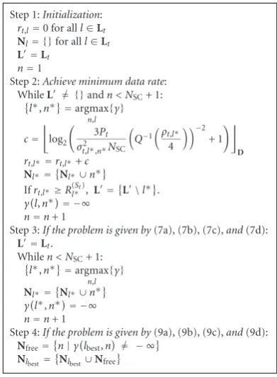
of the set D. Note that the estimation of number of the loaded bits on a subcarrier is conservative since a uniform power distribution among the subcarriers is assumed. The first priority of the algorithm is that the minimum data rate is achieved for all served links. The allocation of the subcarriers which remain if all links achieve their minimum data rate depends on the problem which is solved. If the problem is given by (7a), (7b), (7c), and (7d), the remaining subcarriers are allocated to the links according the highest SNR values. If the problem is given by (9a), (9b), (9c), and (9d), the remaining subcarriers are allocated to the link of the best connection represented by the receiverlbest.
The most complex operations in the algorithm are to find the maximum elements in the matrixγ. The matrix has the sizeNSC× Lt. The search is repeated NSC times. Hence, the complexity of the algorithm depends quadratically on the number of subcarriers and linearly on the number of links and is represented byO(NSC2 Lt).
The bit and power loading algorithm is shown in
Figure 3. It is necessary that each subcarrier is uniquely allocated to a link. After an initialization, the power is allocated with the aim that the minimum data rate is achieved on all served links. If all served links achieve their minimum data rate and some power remains, the remaining
Step 1:Initialization:
rt,l=0 for alll∈Lt
Nl= {}for alll∈Lt
L=Lt
n=1
Step 2:Achieve minimum data rate: While L = {}andn < NSC+ 1:
l∗,n∗=argmax
n,l
{γ}
c=
log2
3Pt
σ2 t,l∗,n∗NSC
Q−1
ρt,l∗
4
−2
+ 1
D
rt,l∗=rt,l∗+c
Nl∗=Nl∗∪n∗
Ifrt,l∗≥R(St) l∗ ,L=
L\l∗.
γl,n∗= −∞
n=n+ 1
Step 3:If the problem is given by(7a), (7b), (7c),and(7d):
L=Lt.
While n < NSC+ 1: l∗,n∗=argmax
n,l
{γ}
Nl∗=Nl∗∪n∗
γl∗,n∗= −∞
n=n+ 1
Step 4:If the problem is given by(9a), (9b), (9c),and(9d):
Nfree=n|γlbest,n= − ∞
Nlbest=
Nlbest∪Nfree
Figure2: Subcarrier allocation algorithm.
power is allocated to the subcarriers according to the power which is required to load two additional bits. If the solved problem is given by (7a), (7b), (7c), and (7d), all subcarriers are considered. Only the subcarriers allocated to the link of the best connection are considered if the solved problem is given by (9a), (9b), (9c), and (9d).
The algorithm can easily be adapted to other modulation and coding schemes. For each modulation and coding scheme, the calculation of the required power increments represented by ΔPn in Figure 3 must be changed and the number of bits given in the setDmust be changed.
The most complex operations of the algorithm are the calculations of the power incrementsΔPnfor all subcarriers and the searches of the minimum power increments over all subcarriers. The highest complexity is achieved if each subcarrier uses the highest modulation and coding scheme. Since three types of modulation and no coding is considered in this paper, the complexity of the search is represented by
O(3NSC) and the complexity of the calculation of the power increments are represented byO(3NSC).
5. Performance Evaluation
In this section, the proposed coordinated resource allocation algorithm is evaluated. InSection 5.1, an evaluation scenario is defined in which the coordinated resource allocation algorithm is analyzed. An upper bound and a static resource allocation algorithm used for benchmarking are defined in
Section 5.2. InSection 5.3, simulation results are presented.
Step 1:Initialization:
rt,l=0 for alll∈Lt
cn=0 for alln ΔPn=
ft,l,n
cn+ 2
−ft,l,n
cn
/α2
t,l,nfor alln
p=0
N=1, 2,. . .,NSC
Step 2:Achieve minimum data rate: Whilep≤PtandN= {}
n∗=argmin
n∈N
ΔPn
p=p+ΔPn∗
Ifp≤Pt, cn∗=cn∗+ 2 Ifcn∗<6,ΔPn∗=
ft,l,n
cn∗+ 2
−ft,l,n
cn∗
/α2t,l,n∗ Ifcn∗=6, ΔPn∗= ∞
Ifrt,l≥R(lSt),N=
N\Nl
Step 3:If the problem is given by(7a), (7b), (7c),and(7d):
N=1, 2,. . .,NSC
Whilep≤Pt
n∗=argmin
n∈N
ΔPn
p=p+ΔPn∗
Ifp≤Pt, cn∗=cn∗+ 2
Ifcn∗<6,ΔPn∗=ft,lcn∗+ 2−ft,lcn∗/α2 t,l,n∗ Ifcn∗=6, ΔPn∗= ∞
Step 4:If the problem is given by(9a), (9b), (9c),and(9d): Whilep≤Pt
n∗=argmin
n∈Nlbest
ΔPn
p=p+ΔPn∗
Ifp≤Pt, cn∗=cn∗+ 2
Ifcn∗<6,ΔPn∗=ft,l,ncn∗+ 2−ft,l,ncn∗/α2 t,l,n∗ Ifcn∗=6, ΔPn∗= ∞
Figure3: Bit and power loading algorithm.
BS
RS
RS
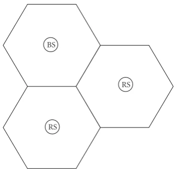
Figure4: Evaluation scenario with three subcells.
two RSs are deployed. The deployment of the scenario is given inFigure 4. The cell consists of three subcells. The SSs are uniformly distributed in the scenario and assigned to the BS or RSs according to a best server algorithm explained in detail in [13].
The parameters chosen for the evaluation are given in
Table 1. The parameters are not conforming to a standard, but specify a general OFDMA system representing basic features of a system according to IEEE 802.16, 3GPP LTE or WINNER. The radius of each of the three subcells is 250 m.
A bandwidth of 5 MHz is chosen. The receiver noise power is the same for all SSs and RSs and has a value of−99 dBm for a bandwidth of 5 MHz. The noise density depending on the frequency is assumed to be constant, so that the noise power on a subcarrier is 1/NSCof the total noise power. The number of subcarriers is NSC = 128 enabling an evaluation of the proposed algorithms at a tractable complexity. An antenna gain of 17 dBi between BS and RSs is assumed in order to achieve an improved channel condition on the first hop of a two-hop connection. As an example, omnidirectional antennas are used for the transmissions between the BS and a SS and between a RS and a SS. If a scenario is considered in which directive antennas are used for the transmissions towards the SSs, the number of slots required by a transmitter
tin order to provide the minimum data rates is decreased in all considered algorithms.
The channel model includes a model for fast fading, slow fading and path loss and is taken from [23]. The path loss formulas depending on the distancedbetween the two stations and the standard deviations of the log-normal fading modeling the slow fading are shown for the different types of links inTable 1.
Each transmission is only reliable according to a given bit error probability given in (1). The bit error probability maximally tolerated on a link depends on the offered service. As an example, a bit error probability ofρ=10−2is chosen which is tolerated on every connection. Note that the dependency between the bit error probability ρmaximally tolerated on a two hop connection and the bit error probability tolerated on a link (t,l) is well approximated by
ρt,l≈1−
1−ρ (21)
according to [24]. The frame duration is chosen to be 100 slots. If the chosen number of slots is too small, the coordinated resource allocation algorithm cannot benefit from the adaptive allocation of slots. Therefore, the number of slots is chosen such that this benefit is revealed at a tractable complexity. Each SS requests the same minimum data rate. Two different scenarios are considered. In the first one, each SS requests 2560 bits per frame and in the second one 640 bits per frame.
In the evaluation scenario, an admission control is considered which decides if a SS is considered in the resource allocation algorithm depending on the SNR values of its used links. The admission control prevents that the coordinated resource allocation algorithm fails in the evaluation scenario because a SS is out of coverage of the BS or the RSs. The SNR value of a link used to serve a SS must exceed a threshold. The SNR value of a link is determined by assuming a uniform power allocation to all subcarriers. The threshold is chosen such that the bit error probability tolerated on a link is ensured by the 4-QAM as the most robust modulation. Using (1), the thresholdTt,lof the admission control is given by
Tt,l=
Q−1
ρ
t,l 4
2
Table1: Parameters.
Parameters Value
Radius of subcell 250 m
Power limit of BS and RSs 35 dBm
Noise power −99 dBm
Bandwidth 5 MHz
Number of subcarriersNSC 128
Antenna gain between BS and RS 17 dBi
Antenna gain between BS and SS and between RS and SS 0 dBi
Path loss from BS to RS in dB wheredis the distance in meters 38.5 + 23.5log10(d)
Path loss from BS to SS and from RS to SS in dB 38.4 + 35log10(d)
Standard deviation of log-normal fading between BS and RS 3.4 dB
Standard deviation of log-normal fading between BS and SS and between RS and SS 8 dB
Maximally tolerated bit error probabilityρper connection 10−2
Frame duration 100 slots
Minimum data rate 2560/640 bits per frame
The SNR of a BS-to-SS link must exceed the threshold of 7.2 dB in the evaluation scenario if a SS is served by a direct connection. If a SS uses a two hop connection, the SNR on its BS-to-RS link and RS-to-SS link must be greater than 6.6 dB.
5.2. Benchmark Algorithms. Two kind of algorithms are defined which serve for a comparison to the introduced coordinated resource allocation algorithm.
The first one is called upper bound algorithm. The oper-ations of the BS and RSs in the upper bound algorithm are defined as in the coordinated resource allocation algorithm given byFigure 1except that the problems defined in (7a), (7b), (7c), and (7d) and in (9a), (9b), (9c), and (9d) are relaxed and solved numerically. The problems defined in (7a), (7b), (7c), and (7d) and in (9a), (9b), (9c), and (9d) are linear integer programs. Their optimal solution is given by an exhaustive search algorithm with a complexity increasing exponentially with the number of variables. Due to the huge complexity the optimal solution cannot be found within an acceptable time. An upper bound for a linear integer program describing a maximization problem is found by a relaxation of the assignment variable. The assignment variables in (7a), (7b), (7c), and (7d) and (9a), (9b), (9c), and (9d) are substituted by real valued assignment variables
uwith 0≤u≤1 andu∈R. The relaxed optimization prob-lems are linear programs since the objective functions and the equality and inequality constraints are linear functions of the assignment variables. The relaxed optimization problems can be solved numerically. Since the search space is extended in the relaxed optimization problem, the sum rate is greater or equal than the sum rate of the original one leading to an upper bound of the sum rate.
The coordinated resource allocation algorithm is addi-tionally compared to an algorithm called static algorithm. As in the coordinated resource allocation algorithm, a frame is split into three subframes but each subframe has a fixed size. Three cases of the static algorithm are considered because the performance of the static algorithm depends on the sizes
of the subframes. In the first one, the subframe in which the BS transmits has a size of 34 slots. Each of the other two subframes has a size of 33 slots. This case represents an algorithm in which each transmitter is allocated the same number of slots. In the second case, the BS is allocated 50 slots and each of the RSs 25 slots. The BS is allocated more slots than a RS in order to consider that resources are required for the BS-to-RS links. In the third case, the BS is assigned 68 slots and each RS 16 slots. The motivation for this allocation is to maximize the sum rate for a large number of SSs. The subframe of the BS is quite large in order to achieve a high sum rate on average since the direct connections achieve a higher data rate than the two hop connections on average. The drawback is that this case of the algorithm fails if the number of SSs assigned to a RS is high. In the static algorithm, the BS and RSs apply the same algorithm for subcarrier allocation and for bit and power loading as in the coordinated resource allocation algorithm. First a RS solves (7a), (7b), (7c), and (7d). The BS finds the best connection and solves (9a), (9b), (9c), and (9d). If a RS is not serving the best connection, only the sum of the minimum data rates of the SSs assigned to the RS is allocated to the corresponding BS-to-RS link. The subcarriers and the power not required by the BS to serve the minimum data rates are completely given to the best connection. If a RS is serving the best connection, the problem defined in (9a), (9b), (9c), and (9d) is also solved at this RS. A comparison of the coordinated resource allocation algorithm and the static algorithm shows the advantage of dynamically assigning slots to the RSs and the BS.
16 14 12 10 8 6 4 2 0
NSS
Upper bound CRAA Static, (68,16,16)
Static, (50,25,25) Static, (34,33,33) Minimum data rates 0
1 2 3 4 5 6 7 ×10⁴
A
ve
ra
ge
su
m
ra
te
in
b
it
s
pe
r
fra
m
e
Figure 5: Average sum rate of resource allocation algorithms depending on the number of SSs. The minimum data rate is 2560 bits per frame.
considered SSs fulfilled the admission control. Each SS has a minimum data rate of 2560 bits per frame. Thus, the amount of requested data rate increases linearly and the subcarriers and slots available for the best connection decrease with an increasing number of SSs. Only frames are considered for an algorithm in which the minimum data rate is offered to all SSs, that is, an algorithm does not fail and the frame building is successful. Only results of an algorithm are shown for which the ratio of failures in the frame building related to the total number of simulated frames is below 5% to avoid that the average sum rate is too optimistic.
The static algorithms achieve a low average sum rate. Only a low number of SSs can be served since the static algorithms fail if a high number of SSs or SSs using a robust modulation are assigned to a single RS or BS. For instance, two SSs which load each subcarrier with two bits require 20 slots to achieve their minimum data rate. A comparison of the static algorithms shows that the algorithm applying a subframe size of 16 slots achieves a higher average sum rate than the other static algorithms since the BS is allocated more slots.
The coordinated resource allocation algorithm called CRAA in the figures and the upper bound algorithm have a similar behavior depending on the number of SSs. For a high number of SSs, a SS can be found more probably which achieves a high data rate on the best connection. Thus, the average sum rate depending on the number of SS increases for a small number of SSs. If the number of SSs increases further, more resources are occupied to provide the minimum data rates and less resources are available for the best connection maximizing the sum rate. Thus, the average sum rate decreases for large number of SSs.
16 14 12 10 8 6 4 2 0
NSS
Upper bound CRAA Static, (68,16,16)
Static, (50,25,25) Static, (34,33,33) 0
1 2 3 4 5 6 7 8 9 10
Rat
e:
fr
ame
building
not
feasible
in
(%)
Figure 6: Rate of how often the frame building fails related to the total number of simulated frames for the different algorithms depending on the number of SSs. The minimum data rate is 2560 bits per frame.
The average sum rate of the coordinated resource allo-cation algorithm is more than 87% of the one of the upper bound algorithm. This result shows that the performance degradation due to the suboptimal greedy algorithms for the subcarrier allocation and the bit and power loading is quite small compared to an optimal solution of the problems defined in (7a), (7b), (7c), and (7d) and (9a), (9b), (9c), and (9d). The coordinated resource allocation algorithm achieves a gain of more than 70% in terms of average sum rate compared to the static algorithm using a subframe size of 25 slots.
A connection which is not chosen as a best connection achieves its minimum data rate plus an increment since only a discrete number of slots, subcarriers and bits can be allocated. Neglecting this small increment, a comparison of the sum of the minimum data rates and the average values of the sum rates depicted inFigure 5reveals the average of the data rates which are achieved by the best connection in addition to its minimum data rate.
60 50 40 30 20 10 0
NSS
Upper bound CRAA Static, (68,16,16)
Static, (50,25,25) Static, (34,33,33) Minimum data rates 0
1 2 3 4 5 6 7 ×10⁴
A
ve
ra
ge
su
m
ra
te
in
b
it
s
pe
r
fra
m
e
Figure 7: Average sum rate of resource allocation algorithms depending on the number of SSs. The minimum data rate is 640 bits per frame.
60 50 40 30 20 10 0
NSS
Upper bound CRAA Static, (68,16,16)
Static, (50,25,25) Static, (34,33,33) 0
1 2 3 4 5 6 7 8 9 10
Rat
e:
fr
ame
building
not
feasible
in
(%)
Figure 8: Rate of how often the frame building fails related to the total number of simulated frames for the different algorithms depending on the number of SSs. The minimum data rate is 640 bits per frame.
resource allocation algorithm as shown in Figure 6. The reason is that the upper bound algorithm achieves an average sum rate which is roughly 6000 bits per frame larger than the average sum rate of the coordinated resource allocation algorithm according toFigure 5.
×104
8 7 6 5 4 3 2 1 0
rt,lbestin bits per frame Upper bound
CRAA Static, (68,16,16)
Static, (50,25,25) Static, (34,33,33) 0
0.1 0.2 0.3 0.4 0.5 0.6 0.7 0.8 0.9 1
CDF
Figure9: CDF of the data rate of the best connection assuming five SSs in a frame and a minimum data rate of 640 bits per frame.
In Figure 7, the average sum rate is given for the algorithms depending on the number of SSs assuming a minimum data rate of 640 bits per frame. Especially, the static algorithms improve in terms of a higher number of SSs which can be served compared to Figure 5 since the minimum data rate per SS is smaller. The coordinated resource allocation algorithm achieves a gain of more than 15% in terms of average sum rate compared to the best static algorithm. The gap between the upper bound algorithm and the coordinated resource allocation algorithm slightly increases because the degradation of the greedy algorithms is stronger if more possibilities of allocations of subcarriers, bits and power exist.
Figure 8shows the rate of how often the frame building fails related to the total number of simulated frames. The rate depends on the number of SSs assuming a minimum data rate of 640 bits per frame. The static algorithm using a subframe size of 16 slots is feasible for the same number of SSs nearly as often as the other static algorithm. Since the motivation of the subframe splitting 68, 16 and 16 slots is to maximize the average sum rate for a large number of SSs, the feasibility is improved for a large number of SSs with a low minimum data rate. The static algorithms serve more SSs than in Figure 6. Figure 8 shows that the coordinated resource allocation algorithm serves approximately 20 SSs more than the static algorithms. The upper bound algorithm serves approximately 12 more SSs than the coordinated.
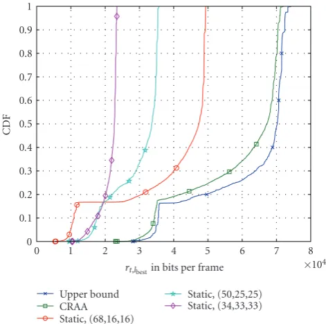
Since the SSs which are not chosen as a best connection achieve approximately their minimum data rate, only the data rate of the SS related to the best connection is affected by strong variations. In Figure 9 the cumulative distribution functions (CDFs) of the data ratesrt,lbest of the
×104
6 5 4 3 2 1 0
rt,lbestin bits per frame Upper bound
CRAA Static, (68,16,16)
Static, (50,25,25) Static, (34,33,33) 0
0.1 0.2 0.3 0.4 0.5 0.6 0.7 0.8 0.9 1
CDF
Figure10: CDF of the data rate of the best connection assuming 21 SSs in a frame and a minimum data rate of 640 bits per frame.
number of SSs considered in a frame is five. The CDFs of the static algorithms using a subframe size of 16 slots and of 25 slots, the coordinated resource allocation algorithm and the upper bound algorithm contain a step at the value of the CDF of approximately 0.18. The step reveals that roughly 18% of the best connections are two hop connections. Since a best connection which is a two hop connection requires slots for the BS-to-RS link and for the RS-to-SS link, the data rate of a two hop best connection is smaller than the data rate of a direct best connection. Since the number of SSs considered in the frame is quite small, the variances of these four CDFs are large. The static algorithm using a subframe size of 33 slots leads to a small variance of the data rate because the number of slots available for the best connection is too small.
In Figure 10, the CDFs of the data rates of the best connections is given assuming that the number of SSs is 21. The probability that the best connection is a direct connection is nearly one. For instance, this can be concluded from a comparison to Figure 9which shows that the steps vanish in the CDFs. The variances of the CDFs are decreased in comparison toFigure 9because the probability tends to one that a best connection is found on which the highest number of bits is loaded on its allocated subcarriers.
6. Conclusions
In this paper, a novel algorithm for subcarrier, bit, and power allocation in a relay network is presented. Since the effort which is caused by bringing the short-term CSI to a central point within a cell is quite large, the algorithm coordinates the allocation of slots, subcarriers, power and bits between the BS and the RSs. The algorithm aims at maximizing the sum rate of a cell while each SSs is guaran-teed a minimum data rate. Simulation results show that the
proposed algorithm achieves a superior sum rate compared to static resource allocation algorithms. Furthermore, the coordinated resource allocation algorithm enables to serve an increased number of SSs compared to static resource allocation algorithms. Simulation results show that a sum rate in a cell is achieved by low-complex algorithms, which is close to an upper bound for the sum rate within a scenario representing typical features of a cell in a relay network.
References
[1] R. Pabst, B. H. Walke, D. C. Schultz, et al., “Relay-based deployment concepts for wireless and mobile broadband radio,”IEEE Communications Magazine, vol. 42, no. 9, pp. 80– 89, 2004.
[2] K. B. Letaief and Y. J. Zhang, “Dynamic multiuser resource allocation and adaptation for wireless systems,”IEEE Wireless
Communications, vol. 13, no. 4, pp. 38–47, 2006.
[3] N. Esseling, H. Vandra, and B. Walke, “A forwarding concept
for HiperLAN/2,” in Proceedings of the European Wireless
Conference, pp. 13–18, Dresden, Germany, September 2000.
[4] B. Timus, “Cost analysis issues in a wireless multihop architecture with fixed relays,” inProceedings of the 61st IEEE
Vehicular Technology Conference (VTC ’05), vol. 5, pp. 3178–
3182, Stockholm, Sweden, May-June 2005.
[5] 3GPP WG1 Tr 25.814, “Physical layer aspects for evolved Uni-versal Terrestrial Radio Access (UTRA),” V7.1.0, September 2006,http://www.3gpp.org/.
[6] EU project WINNER II Wireless World Initiative New Radio,
IST-4-027756,http://www.ist-winner.org/.
[7] C. Y. Wong, R. S. Cheng, K. B. Letaief, and R. D. Murch, “Multiuser OFDM with adaptive subcarrier, bit, and power allocation,”IEEE Journal on Selected Areas in Communications, vol. 17, no. 10, pp. 1747–1758, 1999.
[8] I. Kim, I.-S. Park, and Y. H. Lee, “Use of linear program-ming for dynamic subcarrier and bit allocation in multiuser OFDM,”IEEE Transactions on Vehicular Technology, vol. 55, no. 4, pp. 1195–1207, 2006.
[9] M. Bohge, J. Gross, A. Wolisz, and M. Meyer, “Dynamic resource allocation in OFDM systems: an overview of cross-layer optimization principles and techniques,”IEEE Network, vol. 21, no. 1, pp. 53–59, 2007.
[10] Y.-J. Chang, F.-T. Chien, and C.-C. J. Kuo, “Cross-layer QoS analysis of opportunistic OFDM-TDMA and OFDMA networks,”IEEE Journal on Selected Areas in Communications, vol. 25, no. 4, pp. 657–666, 2007.
[11] G. Song and Y. Li, “Cross-layer optimization for OFDM
wireless networks—part I: theoretical framework,” IEEE
Transactions on Wireless Communications, vol. 4, no. 2, pp.
614–624, 2005.
[12] G. Song and Y. Li, “Cross-layer optimization for OFDM
wireless networks—part II: algorithm development,” IEEE
Transactions on Wireless Communications, vol. 4, no. 2, pp.
625–634, 2005.
[13] C. M¨uller, A. Klein, F. Wegner, and M. Kuipers, “Costs and performance of non-cooperative relay networks,” in
Proceedings of the 13th European Wireless Conference, pp. 1–7,
Paris, France, April 2007.
[14] L. Huang, M. Rong, L. Wang, Y. Xue, and E. Schulz, “Resource allocation for OFDMA based relay enhanced cellular net-works,” inProceedings of the 65th IEEE Vehicular Technology
Conference (VTC ’07), pp. 3160–3164, Dublin, Ireland, April
[15] C. M¨uller, A. Klein, F. Wegner, M. Kuipers, and B. Raaf, “Dynamic subcarrier, bit, and power allocation in OFDMA-based relay networks,” inProceedings of the 12th International
OFDM-Workshop, Hamburg, Germany, August 2007.
[16] K.-D. Lee and V. C. M. Leung, “Fair allocation of subcarrier
and power in an OFDMA wireless mesh network,” IEEE
Journal on Selected Areas in Communications, vol. 24, no. 11,
pp. 2051–2060, 2006.
[17] F. P. Kelly, A. K. Maulloo, and D. K. H. Tan, “Rate control for communication networks: shadow prices, proportional fairness and stability,” Journal of the Operational Research
Society, vol. 49, no. 3, pp. 237–252, 1998.
[18] M. Kaneko and P. Popovski, “Adaptive resource allocation in cellular OFDMA system with multiple relay stations,” in Proceedings of the 65th IEEE Vehicular Technology Conference
(VTC ’07), pp. 3026–3030, Dublin, Ireland, April 2007.
[19] M. Kaneko and P. Popovski, “Radio resource allocation algorithm for relay-aided cellular OFDMA system,” in Proc-cedings of IEEE International Conference on Communications
(ICC ’07), pp. 4831–4836, Glasgow, Scotland, June 2007.
[20] C. Guthy, W. Utschick, J. A. Nossek, and G. Bauch, “Sum throughput maximization in quality of service constrained multiuser MIMO systems based on perturbation analysis,”
in Proceedings of ITG/IEEE Workshop on Smart Antennas
(WSA ’07), Vienna, Austria, February 2007.
[21] M. Dottling, M. Sternad, G. Klang, J. von H¨ofen, and M. Olsson, “Integration of spatial processing in the WINNER B3G air interface design,” in Proceedings of the 63rd IEEE
Vehicular Technology Conference (VTC ’06), vol. 1, pp. 246–
250, Melbourne, Australia, May-July 2006.
[22] D. E. Knuth,The Art of Computer Programming, Volume 3:
Sorting and Search, Addison-Wesley, Reading, Mass, USA, 2nd
edition, 1998.
[23] IST-2003-507581 WINNER D5.4 v. 1.00, Final Report on
Link and System Level Channel Models, 2005,
http://www.ist-winner.org/.
[24] G. Ferrari and O. K. Tonguz, “Impact of mobility on the BER performance of ad hoc wireless networks,”IEEE Transactions