---
---
- -
-
-
- - -
-
- - -
----
-
-
---
---_
.
-•
.
"
,
J
,
.
'
. 1
GA34
-
0025-1
File No. S1-03
IBM
'
Series/1
4974 Printer
Description
_._-
---
-
- - - -
-
- - - -
-
----
-
-
---
---
--_.-(
~'. /
GA34-0025-1
File No. S1-03
IBM Series/1
4974 Printer
Description
Second Edition (March 1977)
This is a major revision of, and obsoletes GA34-0025-0. Significant changes in this new edition include:
Restructuring of status words
Changing the format of data flow information
Changes are periodically made to the information herein; any such changes will be reported in subsequent revisions or Technical Newsletters. Before using this publication in connection with the operation of IBM systems, have your IBM representative confirm editions that are applicable and current.
Requests for copies of IBM publications should be made to your IBM representative or the IBM branch office serving your locality.
A form for readers' comments is provided at the back of this publication. If the form has been removed, send your comments to IBM Corporation, Systems Publications, Department 27T, P.O. Box 1328, Boca Raton, Florida 33432. Comments become the property of IBM.
c~'
C
'"~·
',,)Preface v
Prerequisite Knowledge v Prerequisite Publications v Related Publications v
Chapter 1. Introduction 1-1 Printer Functional Description 1-1
Attachment Feature Functional Description 1-2 Standard Features 1-2
Cycle Steal 1-2 Character Set 1-2 Basic Components 1-2
Printer 1-2
Forms Tractor Unit 1-4 Controls 1-5
Chapter 2. Programming Input/Output Operations 2-1 Data Transfer Operations 2-1
Direct Program Control (DPC) 2-1 Cycle Steal 2-1
Initiating a Printer Operation 2-1 Operate I/O Instruction 2-1 Using the IDCB 2-2
Input/Output Commands and Printer Operations 2-2 Command Execution Under DPC Mode 2-2 Command Execution in CS Mode 2-4 Using the DCB 2-5
Status Information 2-11 Condition Codes 2-11
Condition Code O-Device Not Attached 2-11
Condition Code I-Busy 2-11
Condition Code 2- Busy After Reset 2-11 Condition Code 3-Command Reject 2-11 Condition Code 5-lnterface Data Check 2-11 Condition Code 7-Satisfactory 2-11 Condition Code 2- Exception 2-11 Condition Code 3-Device End 2-11 Condition Code 4-Attention 2-11 Interrupt Identification Word 2-12 Interrupt Status Byte 2-12 Cycle Steal Status Words 2-12 Residual Address-Word 0 2-12 Device Status-Word 1 2-14 Status After Power On and Resets 2-15
Contents
Appendix A. EBCDIC Character-Hexadecimal Equivalent A-I
Appendix B. Printer Forms B-1 Cut Forms B-1
Continuous Forms B-1
Appendix C. Wire Image Table C-l
General Description C-l
Wire Image Character Pattern Generation C-l Wire Image Table Structure C-l
Wire Image Table Generation C-2
(r~
I
~
J
c
CJ
This manual contains reference material and is a source of
information about the IBM Series/l 4974 Printer, and the
4974 Printer Attachment Feature.
Chapter 1 is an introduction to the general characteristics
and features of the 4974.
Chapter 2 discusses the data flow between the processor
and the 4974. Specific topics are:
• I/O Commands
• I/O Operations
• Status Information
Appendix A contains EBCDIC characters and
hexa-decimal equivalents.
Appendix B contains information on printer forms.
Appendix C contains information on building a Wire
Image table.
Preface
Prerequisite Knowledge
This book assumes the reader has a background in data
processing and is familiar with the hexadecimal numbering
system as used in IBM systems.
Itis assumed the reader
has a basic understanding of printers and their relationship
to a processor and an understanding of stored program
concepts.
Prerequisite Publications
IBM Series/l Model
5 4955Processor and Processor
Features Description, GA34-0021
IBM Series/l Model
3 4953Processor and Processor
Features Description, GA34-0022
IBM Series/l System Summary, GA34-0035
Related Publications
IBM Series/l Installation Manual-Physical Planning,
GA34-0029-1
c
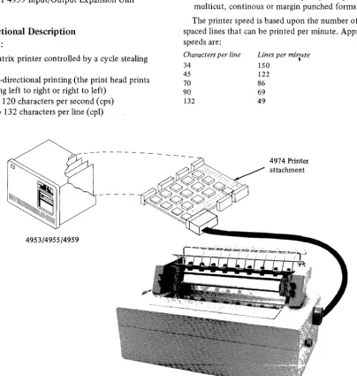
The
IBM
Series/l 4974 Printer (Figure 1-1) is a table top
wire matrix printer that produces characters printed by a
pattern of dots, and provides medium speed output for the
IBM
Series/I.
The printer connects to the attachment card (a
prerequisite for the 4974 printer) which is located in one
of the following rack mounted units:
• IBM
Series/l ModelS 4955 Processor
• IBM
Series/l Mode13 4953 Processor
• IBM
Series/l 4959 Input/Output Expansion Unit
Printer Functional Description
The
IBM
4974:
• Is a wire matrix printer controlled by a cycle stealing
attachment
• Performs bi-directional printing (the print head prints
while moving left to right or right to left)
• Operates at 120 characters per second (cps)
• Prints up to 132 characters per line (cpl)
~
IIIIIIIIIIIIIIIIIIIIIIIIIIIIII~II
111111
4953/4955/4959
Chapter 1. Introduction
• Prints 10 characters per inch (cpi) with a maximum line
width of 33.5cm (13.2 in.)
• Prints 6 lines per inch (lpi)
• Spaces with a maximum of 84 lines per command
• Can skip to any line on the form
• Suppresses unprintable characters
• Uses the EBCDIC (Extended Binary Coded Decimal
Interchange Code) 64-character set (See Appendix A,
"EBCDIC Character-Hexadecimal Equivalent Codes")
• Has a Forms Tractor that accepts up to 6-part, cut,
multicut, continous or margin punched forms
The printer speed is based upon the number of single
spaced lines that can be printed per minute. Approximate
speeds are:
Characters per line
34 45
70
90
132
Lines per mi'lute
150 122
86
69 49
[image:8.617.120.525.257.682.2]4974 Printer attachment
Attachment Feature Functional Description
The attachment feature card:
• Serves as the connection between the processor and
printer
• Transfers characters from processor storage to the
printer
• Converts the processor storage characters into a
printable dot matrix
• Contains a wire image buffer used in generation of the
dot matrix
• Controls form movement (see note)
Note.
The using system's program can define, through the
attachment, the length of the forms and the overflow line
on the form.
Standard Features
Cycle Steal
The 4974 operates in cycle steal mode. In cycle steal
mode the I/O operations are overlapped with processing
operations, so that processing can continue while I/O
operations are in progress.
Character Set
The printer uses the EBCDIC 64-character set, however, the
attachment will accept any 8-bit character code (defined
and selected by the user and user alterable) and print up
to a 96-character set. The 4974 has the ability to self
initialize the basic character set. For other than the
standard character set, refer to Appendix A, "EBCDIC
Character Hexadecimal Equivalents" and Appendix C,
"Wire Image Table."
Basic Components
The 4974 Printer consists of two basic components:
• Printer
• Forms Tractor Unit
Printer
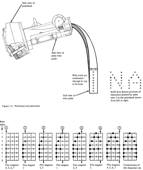
The printing operation, moving the printhead and printing
dots, is controlled entirely by the attachment. Characters
are formed by printing a pattern of dots in a vertical
arrangement that corresponds to a stored matrix in the
Wire Image Buffer of the attachment. The character-pattern
matrix used by the printer is 8-high by 7 -wide.
When a character is to be printed, the printhead moves
horizontally across the paper, along the print line, while
selectively firing the print wires against the ribbon to
make the dots. Figure 1-2 shows a side view of the
c
print head Side view ofprint wire guide
Print wires are numbered 1 through 8, top to bottom
[image:10.615.66.557.55.640.2]End view of wire guide
Figure 1-2. Printhead and printwires
Print 2 3 4 5 6 7 8 1 ~
·
·
,
,·
·
,·
·
·
,
,
I I·
·
·
Fire magnets 4,5,6,7 Fire magnet 3 3 ~-
·
-
-.-.
·
,
I
-.-I
.
·
,
·
Fire magnets
2; 5
Fire magnet 1 Fire magnets 2,5 0 0 0 0 0 0 0 Fire magnet 3
0 0 0 0 0 0 0
• • •
•
•
0 0 0 0 0 0 o 0 0 0 0 0 0 0 0 0 0 0 0 0
Solid dots denote portions of characters printed by print wire 3 as the printhead moves from left to right.
--
.
-'-.
I-
--
,
-.
I I
,
I I I IFire magnets Construction of 4,5,6, 7 the character (A)
is complete. This illustrates how the character A is formed by firing a combination of 7 print wires within a matrix (a character position). The numbers of the print wires are shown at the far left. The sequence of firing positions, within the matrix is shown from left-to-right across the page. Note that no magnet is fired in successive firing positions.
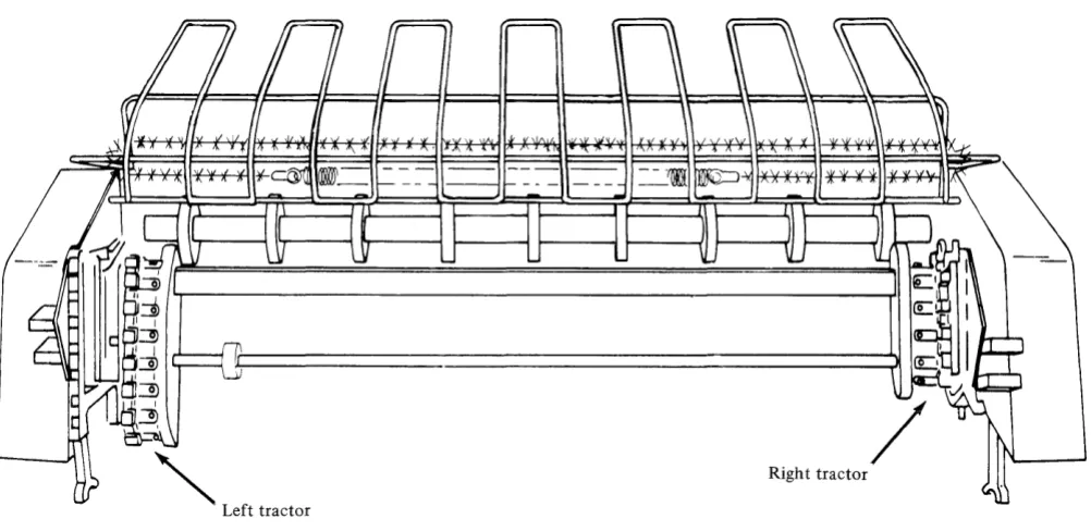
Forms Tractor Unit
The Forms Tractor (Figure 1-4) is that portion of the
printer which causes movement of the installed forms. The
Forms Tractor is required for printing on multiple part
continuous forms or preprinted continuous forms. The unit
snaps into place on top of the printer frame and can be
pivoted back out of the way when cut forms are to be used.
The right and left tractors on the unit are adjustable to
handle different size paper. (See Appendix B, "Printer
Forms" for more information concerning paper size.)
[image:11.613.44.545.200.444.2]'"
Left tractor Figure 1-4. Forms tractor unit/
Righ t tractor
C~
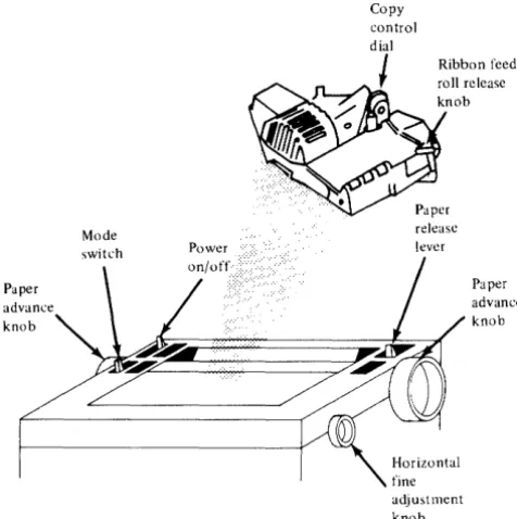
Controls
The printer has several controls for moving and adjusting paper and forms. (See Figure 1-5 for locations of the controls.) There are two switches located on the printer, one for powering the unit and the other for servicing. They are:
• Power switch • Mode switch
Power Switch
The Power Switch is used for powering the printer on/off.
Paper advance knob
Figure 1-5. Printer controls
Copy
Ribbon feed roll release knob
release lever
Paper advance knob
adjustment knob
Mode Switch
The Mode switch is in front of the Power Switch and has three positions:
• Print • Wait
• Top of Forms
For normal operation the switch should be in the Print position.
Print. In this position, the printer is available for execution of system commands. If no system commands are issued within approximately a 6-second period, the attachment moves the printhead to the extreme left position.
When the printer has been in the Wait state and then moves to the Print state, the attachment corrects the print head to the print position.
Wait. In this position, the printer is no longer available for execu ting system commands. The current command is completed and all printer action is stopped. Once the current command is completed, the printer will ignore any forms or print head movement. In this position, forms can be moved manually for alignment.
Top of Forms. In this position, the attachment will set the positions of the forms to line one. As long as the switch is in this position, the forms position will be line one regardless of manual forms movement. This allows for alignment to the top of the form.
Note.
For detailed descriptions of all printer operator controls, refer to theSeries/l Operators Guide,
[image:12.617.62.300.224.463.2]C,',,'\
,,'o
Chapter 2. Programming Input/Output Operations
This chapter discusses the flow of data to and from the printer. Specific topics are commands, status information and I/O Instructions.
Data Transfer Operations
Data is transferred between the processor and the attach-ment, in a parallel operation (I6 data bits plus 2 parity bits). The number of data words transferred and the direction in which they move is determined by the I/O command. The I/O ,command also determines whether data is transferred to or from processor storage, under Direct Program Control (DPC) only, or under Direct Program Control and in Cycle Steal (CS) mode.
Direct Program Control (DPC)
Under direct program control, only one word of data moves to or from processor storage at a time. After moving the data, the processor continues processing other instructions. Moving data under DPC does not cause interrupts.
Cycle Steal
When data is moved to or from processor storage by stealing storage cycles (Cycle Steal mode), processing and I/O operations are overlapped. Overlapping multiple data transfers allow the processor to execute other instructions while the printer is performing I/O operations.
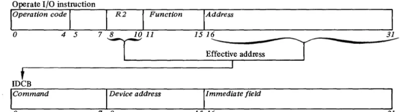
Operate I/O instruction
loperation code
I
I
R2I
FunctionInitiating a Printer Operation
Every input/output operation to the 4974 requires (in processor storage):
1.
An Operate I/O instruction2. An I/O command, device address, an immediate data field
Operate I/O Instruction
The following description is an overview of the Operate I/O instruction. Refer to the Processor Description Manuals listed in the "Prerequisite Publications" section of the Preface for a more detailed description.
All input/output operations from the processor to the printer, are initiated by an Operate I/O Instruction. An address field (bits 16-31) and the R2 field (bits 8-10) in the Operate I/O instruction (Figure 2-1) point to a processor storage location containing an IDCB (Immediate Device Control Block). The IDCB is a two-word block of storage, that contains the device directed I/O commands. Before issuing the I/O instruction for an operation, the command field of the IDCB (Bits 0-7) must be set, along with a device address (bits 8-15), and any field of
immediate data required by the command,in the IDCB (bits 16-31). The information specified in the immediate field depends on the command to be performed. The device address of the 4974 can be one of 128 (0-127) possible device addresses. This address is determined by the Device Address Field of the IDCB. Bit 8 of this field must be zero.
IAddress
I
0 4 5 1516 ~ ____________ -~
E;::ive address
I
I
t
IDeB
Command Device address Immediate field
[image:14.621.108.525.500.613.2]o
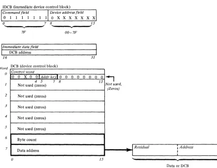
7 8 15 16 31Using the IDCB
An Immediate Device Control Block (IDCB) is required for
every I/O command issued to the printer. The format of
the IDCB is shown in Figure 2-2. Before issuing an I/O
instruction, an I/O command must be stored in the
associ-ated IDCB. The immediate data field of the IDCB should
contain either a data word or a DCB address. I/O commands
that execute under direct program control require a data
word, while the commands that execute in cycle steal
mode require a DCB address.
IDCB (immediate device control block)
Command field Device address field
X X X X X X X X X X X X X X X X
o
7 8 15OO-FF
Immediate data field
DCB address/immediate data word
[image:15.620.48.243.210.342.2]16 31
Figure 2-2. IDCB format
IDCB (immediate device control block)
Input/Output Conlmands and Printer Operations
The I/O command, stored in the IDCB, determines whether
a single word of data is transferred under direct program
control only or following a direct program control
operation, additional words of data are to be transferred
to the processor under cycle steal mode. The 4974 responds
to the following I/O commands (defined in the command
field (bits 0-7) of the IDCB):
Direct Program Control (DPC)
1.
Prepare
2.
Device Reset
3.
Read Device ID
Cycle Steal Mode (CS)
1.
Start
2.
Start Cycle Steal Status
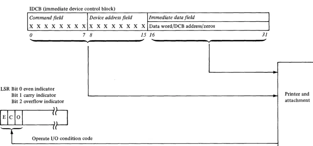
Command Execution Under DPC Mode
When the printer executes aPrepare, Device Reset, or Read
ID command, a word of data is moved to or from the
immediate data field of the IDCB in processor storage.
These commands do not cause interrupts. After execution
of the command, the 4974 reports a condition code that
indicates whether the I/O operation succeeded or failed.
See "Condition Codes" later in this chapter. Processing
operations are halted while the I/O operation is in progress.
Figure 2-3 shows command execution under DPC mode.
Command field Device address field Immediate data field
X X X X X X X X X X X X X X X X Data word/DCB address/zeros
o
7 8 15 16 31~
L SR Bit 0 even indicator
Bit 1 carry indicator Printer and
Bit 2 overflow indicator attachment
E!cI0
l
~~
i
Operate I/O condition codeFigure 2-3. Command execution under DPC
(r~
[image:15.620.49.556.406.642.2]Prepare Command
Before the printer can execute interrupt causing commands, it needs interruption parameters. These parameters, stored in the IDCB immediate field associated with a Prepare command, contain the level on which the attachment is to interrupt (bit
27-30),
and an interrupt enable (bit31).
These bits are transferred to the attachment upon execution of Prepare commands. If the I-bit (bit 31) equals 1, the printer can interrupt. If the I-bit equals 0, it cannot. The Prepare command operates under DPC and does not cause an interrupt.
IDeB (immediate device control block)
Command fie Id Device address fie ld
o
1 1 0 0 0 0 0 0 X X X X X X Xo
7 8 1560 00-7F
,Immediate data field
Zeros Level
16 26 27 3031
Device Reset
A Device Reset command will: • Halt any Start command
• Stop all cycle stealing, printing and carriage movement • Reset Control, Status and Pending interrupts
• Reset the ISB
• Restore the printhead to the left margin
The command code and device address supply all needed information. Although the immediate data field is not used or checked, these bits should be set to zero. The Device Reset command operates under DPC and does not cause an interrupt.
Note.
If the carriage was moving at the time of the Device Reset command execution, the forms may have to be realigned.IDeB (immediate device control block)
Command field Device address field
o
1 1 0 1 1 1o
X X X X X X Xo 7 8 15
IImmedia te data field
Not used
16 31
Read Device
ID
The Read Device ID command transfers the device ID word for the printer into the immediate field of the Immediate Device Control Block (IDCB) associated with that
command. If the printer is busy or an interrupt is pending, condition code 1 is returned. The Read Device ID command operates under DPC and does not cause an interrupt.
IDeB (immediate device control block)
Command field Device address field
0 0 0 0 0 0 1 0 0 0 0 0 0 1 1 X
o
78 15Immediate data field
0 0 0 0 0 0 0 0 0 0 0 0 0 0 0 0
Command Execution in
CS
Mode
The Start command and the Start Cycle Steal Status
command are interrupt-causing commands, and move data
under both direct program control and cycle steal mode.
When the attachment receives and accepts either of these
commands, it reports a condition code to the processor
and begins command execution. The processor continues
with other operations while the attachment is "busy" with
the I/O operation. When the I/O operation is completed,
the attachment sends an interrupt request to the processor.
At interrupt presentation time the attachment reports a
condition code and transfers an interrupt identification
word containing status information to the processor. See
"I/O Status Information" later in this chapter.
The immediate data field of an IDeB containing either
a Start command or a Start Cycle Steal Status command
must point to a Device Control Block (DC B). The DCB must
contain the control information and device parameters that
are required to execute an I/O operation in cycle steal
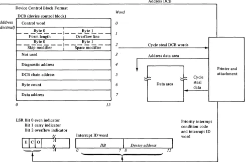
mode. Figure 2-4 shows command execution in CS mode.
Device Control Block Format
DCB (device control block)
DeB dddress Control word
(hexadecimal) . ,
_ _ ....!lyte
L __
1 _ _ _ ByteL __
Form length I Overflow line Byte 0 I Byte 1
I-- - -
-1- - -
-
-
-Skip modifier I Space modifier
Not used
Diagnostic address
DCB chain address
Byte count
Data address
o
LSR Bit 0 even indicator Bit 1 carry indicator Bit 2 overflow indicator
15
Interrupt ID'word
lIB
o
Note. DCB format is shown for a start command. The DCB format for a start cycle steal status command appears later in this chapter.
Figure 2-4. Command execution in cycle steal mode
Word 0 1 2 3 4 5 6 7
7 8
Address DCB
Cycle steal DCB words
Address data area
~
J
Data areaDev ice address
15
1
Cycle steal dataPriority interrupt condition code and interrupt ID word
[image:17.617.59.550.332.656.2]C
""
I,. /
C'
, 'i/U sing the
DeB
A Device Control Block (DCB), comprised of eight con-tiguous words in processor storage, must be reserved for every I/O operation that moves data in cycle steal mode. All Start commands, Start Cycle Steal Status commands, and all printer operations included in a DCB command chaining sequence require a separate DCB. Device parameters that define and control the I/O operation must be stored in each DCB.
Word DCB (device control block)
o
Control word Byte 0 I Byte 1~ - For-;-length -
-1- -
Overflowlin;-2 1 - - - - -Byte 0 - - - -
I.
- - - -Byte 1Skip modifier
I
Space modifier3 Not used 4 Diagnostic address 5 DCB chain address 6 Byte count 7 Starting data
o
15DCB Format
The following text will describe the bit significance of each of the eight contiguous data words in the DCB.
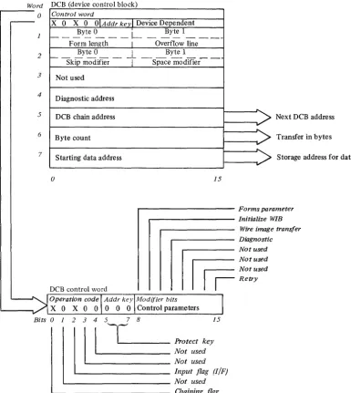
Control Word-DCB Word 0
The control word is the first word of the DCB. It is a 16-bit word that explains the cycle stealing operation, and contains two distinct bytes of control parameters to be used with the particular Start command to be performed. Figure 2-5 shows the DCB and Control Word O.
DCB Word O-Control Word
Word DCB (device control block)
....----o
Control word-
x
0 X 0 OIAddr kevl Device Dependentf---~Y~~--I- __ ~Ytel _ _ _ _ _ Form length I Overflow line
2 ___ ~te 0 __ __ ~ Byte 1
Skip modifier
T
Space modller-I
3 Not used
4
Diagnostic address
5 DCB chain address 6 Byte count
7 Starting data address
o 15
Next DCB address
Transfer in bytes
Storage address for data
. . . - - - Forms parameter . . . - - - Initialize WIB
Wire image transfer
. . . - - - Diagnostic
DCB control word
II
I
~~:;::=
I
Retryr---.---~---
__
Operation code \ Addr keylModljier bitsX 0 X 0 0 0 0 0 \ Control parameters
Bits 0 1
2
1 3
1
4
1
5TI----7
8 Protect ke;5. Not used
Not used
L - -_ _ _ _ _ _ _ _ Input flag (I/F)
'--_________________ Not used '--______________________ Chaining flag
Figure 2-5. DCB and it's control word
[image:19.617.102.487.221.652.2]o
Bits 1,3 and 4 of the control word are not supported and should be zero.
Bit O-Chaining Flag
This bit when = to 1, indicates a command chaining operation. After completing the current DCB operation, the attachment will not interrupt but will fetch the next DCB pointed to by the Chain Address in DCB word 5. Command Chaining is valid only for a Start I/O command. It is ignored and not checked for by the other commands.
Bit 2-I/F (Input Flag)
This bit indicates the direction of the cycle steal data transfer:
o
=
out of processor storage, 1 = into processor storage. Bits 5,6 and 7-Address KeyThis is a 3-bit key presented by the attachment during data transfers to ascertain storage access authorization. An incorrect Address key will cause an exception interrupt.
Bits 8 thru 15 (the second byte of the control word) are device dependent.
Bit 8-Forms Parameter Bit
This bit is an indicator telling whether forms parameters are available in the DCB. If this bit = 0, word 1 of the DCB is not used. If this bit = 1, word 1 of the DCB contains new forms parameters.
Byte 0
=
the number of lines on one form (form length). This can be a value of 1 to 255. Zero is invalid and sets an interrupt with a specification check in the Interrupt Status Byte. See "Interrupt Status Byte" later in this chapter. Byte 1 contains the line where the overflow interrupt is desired and can occur only once per form. The first time an overflow line is reached, the forms stop and no printing occurs. The attachment gives an exception interrupt with bit 0 on in the ISB, and sets an overflow bit in cycle steal status word 1. This interrupt can be used to skip over the folds on forms and to print trailers or headers on forms. Bits 9, 10, and 11 are mutually exclusive. If more than one of these bits are detected in the same DCB control word, an exception interrupt with a DCB specification check is reported. For printing to take place, bits 9, 10 and 11 must be zero.The printer provides the facility to load the wire image buffer with the standard 64-character EBCDIC set, to overlay some of these characters with special characters and symbols, or for the system user to load his own character set. Bits 9 and 10 control the selection of these facilities.
Initialization of the Wire Image Buffer must take place in order for printing to take place. Power on reset initializes the wire image buffer with the standard 64 character U.S. EBCDIC set. If other than the standard character set is to be used, the wire image buffer must be altered after power on reset using bits 9 or 10.
The character set identifying bits for the 4974 are: 0000000000000000 (eight bytes in hex).
Bit 9- Initialize Wire Image Buffer
When this bit is ON, the attachment will initialize its Wire Image Buffer (WIB). During this time no printing or forms movement takes place. There are two ways the WIB is initialized:
1. Byte Count = 0-The attachment initializes its WIB with the standard 64-character EBCDIC set. The system does not have to supply any data table in this mode.
2. The Byte Count is 8 or less- The attachment initializes its WIB with the standard 64-character set and then overlays characters in the table with alternate characters specified by the eight bytes of data transferred. The data transferred is bit significant, where each bit represents an alternate character. If the first bit is on, the first alternate character (see Appendix A and C) will overlay the appropriate character (EBCDIC equivalent) in the standard character set. If the second bit is on, the second alternate character is placed in the buffer and so on up thru the 64th bit. If more than one alternate character is specified with the same EBCDIC representation, the last one specified is the one placed in the WIB.
Note. The Input/Output bit must equal 0 when Bit 9 is on. If
the I/F bit equals 1, an exception interrupt with a DCB Specification check is reported.
Bit 10-Wire Image Transfer
When this bit is ON, the data transferred between processor storage and the attachment is to the Wire Image Table. No printing takes place while this bit is on. The byte count must be 1792 or less, depending on the character set. See Appendix C for more information.
Bit 11-Diagnostic
When this bit is ON, the data transferred between processor storage and the attachment will be diagnostic information. The attachment will transfer data between processor storage and the diagnostic address of the attachment specified in DCB word 4. If the I/F bit = 0 and the last byte transferred is on a word boundary, the attachment will branch to the last diagnostic address accessed when the byte count goes to O.
Bits 12-14-Not used
Bit IS-Retry
When this bit is ON, the attachment will attempt to complete execution of the last Start I/O command issued. If this bit is on the remainder of the DCB must be the same as the DCB being
ex~cuted
at the time of the exception interrupt (the printerattachment knows what step of the execution was in process when the exception occurred, DCB transfer, data transfer, carriage movement or printing).
Forms Parameters- DCB Word 1
This word is not used if bit 8 of DeB Word 0 =
O.
If this bit=
1, word 1 is used for forms parameters. Byte 0 is the new form length. If it is less than the current line position, the current line position is set to line one.Byte 1 is the line where the printer is to stop form movement and/or printing and post an exception interrupt with Bit 0 on in the ISB. Cycle Steal Status word 1 will have the overflow bit (11) set on. This enables the printer to skip over restricted printing areas 0.5 inch from the folds. A Start Cycle Steal Status I/O command is issued to determine how many lines are required to complete the previous carriage operation (the residual line count) and/or the current line position status. Overflow interrupt is inhibited if Byte 1 = 0 or greater than the form length (Byte 0). Forms Control-DCB Word 2
The Forms Control Word specifies whether a skip or space is to take place. For a skip, the attachment calculates how far the forms must be moved to get to the specified line. To space, the user tells the 4974 how many lines to move. The speed of the forms movement is the same, regardless of the modifier used.
Byte 0 of the forms control word is the skip. If this byte has a value between 0 and the maximum form length, the forms will move to that specified line. The printer will skip to the specified line on the next form if the line the form is presently on is equal to or less than the skip modifier. If the skip modifier is greater than the form length, an interrupt is posted and the DeB specification check is set in the ISB.
If Byte 0
=
0, Byte 1 is inspected for a space. IfByte 1
=
0, no forms movement will take place. If the space modifier is greater than zero the forms will move the number of lines specified. (If Byte 0 is greater than zero, Byte 1 is not checked.)The maximum number of lines the forms should be moved with either a skip or space command is 84. When more than 84 lines ( 14 inches) of paper are moved in one operation, stacking and feeding problems occur.
DCB Word 3-Not Used
Diagnostic Address- DCB Word 4
When the diagnostic bit (11) is set in the DCB Control word, this word contains the address in the attachment where the diagnostic data transfer is to take place.
Chaining Address-DCB Word 5
This is the location of the next DCB table to be executed. If the chain address is odd, an interrupt is posted and a DCB specification check is set in the ISB. The chaining address is not checked unless the chaining flag is on in a valid control word.
Byte Count-DCB Word 6
If the byte count = 0, no data is transferred. If the byte count is greater than the maximum allowed for a particular operation, an interrupt is posted and a DeB specification check (bit 3) is set in the ISB.
For a Start I/O command with a modifier of "0000" the byte counts are:
Control Word Bits
Bit 9
=
1 Bit 10 = 1 Bit 11 = 1 Bits 9, 10, 11 = 0Maximum Byte Count 8 1792 *2048 132 Function
Initialize Wire Image Buffer Wire Image Transfer Diagnostic Mode Line Printing
*If the diagnostic transfer address is zero, the maximum byte count is 2048. If the address is greater than zero, the maximum byte count will be equal to 2048 minus the diagnostic transfer address. The attachment stops cycle stealing when the byte count goes to zero.
Data Address-DCB Word 7
This word contains the system storage address for the data associated with the operation to be performed.
Programming Considerations When Using the DCB
1. The entire DeB is fetched, but only the required words are checked. The contents of the words must be specified correctly.
2. The DeB address, chain address, and the status address must be even.
DCB Command Chaining
DCB command chaining is executed when the current DCB comes to a normal completion and a new DeB is fetched without issuing a new Operate I/O instruction. The DCBs belonging to such a sequence are said to be chained.
The first DCB in the chain contains the address of the next DeB. As each operation in the sequence is completed, the attachment uses the chain address stored in the current DCB to select the next DCB. The chained-to DCB is examined to determine which operation is next in the sequence and whether the associated device parameters are valid. DCB command chaining operations continue until a DCB is fetched having the chaining bit in the control word (DCB word 0) set to zero. This indicates the last operation in the chain.
If an error occurs, chaining to succeeding DCBs is automatically suspended, and the attachment sends an interrupt request to the processor. The attachment does not request an interrupt until the last DCB operation in the chain is completed. By using command chaining, the processing time required to execute I/O operations is reduced.
As stated previously, the 4974 responds to the Start
c
o
Start I/O Command
The Start command initiates all printer operations that transfer data to or from processor storage under direct program control and then in cycle steal mode. When the Operate I/O instruction is issued, the Start command is transferred under direct program control from the IDCB to the printer. While the printer is 'busy' executing the I/O operation, the processor continues with other operations. Beginning at the immediate field containing the DCB address specified in the IDCB, the eight words in the DCB are transferred to the printer from processor storage. The data is transferred in cycle steal mode one word at a time. The DCB information is decoded and the printer begins executing the operation called for in DCB control word (DCB word 0). Refer to "Control Word-DCB Word
0."
When the operation (or operations when chaining) ends, an interrupt request is sent to the processor. At interrupt presentation time, a condition code and an interrupt ID word containing status information are presented to the processor.Note.
A Start I/O command issued to the printer while the device is Not-Ready, causes an interrupt with condition code 2 (Exception) and bit 0 (Device Dependent Status Available) set in the ISB. The Start command will not be executed. The format of the IDCB for the Start comand is:Operate I/O instruction
loperation code
I
I
R2I
Function0 4 5 7 8 10 11
IAddress
15 16
T
t
Effective addrei=
IDeB
Command field Device address field Immediate data field
0 1 1 1 0 0 0 0 0 X X X X X X X
o 7 8 15 16
31
Start Cycle Steal Status Command
The Start Cycle Steal Status command initiates the transfer of up to 6 bytes of status information from the printer attachment to processor storage. This status information is used to determine why a given command did not execute properly. The processor storage address is specified in word 7 of the applicable DCB. This command operates under direct program control and in cycle steal mode and causes the attachment to present an interrupt request when execution is complete.
The Start Cycle Steal Status command requires an Operate I/O instruction with the address of an IDCB, an IDCB with the address of the DCB, and a DCB. Figure 2-6 shows the formats of the IDCB, DCB and 6 bytes of status information.
IDeB (immediate device control block)
Device address field Command field
o
1 1 1 11 lOX X X X X X X
7F 00-7F
IImme
di4te data fieldDeB address
16 31
Word DeB (device control block)
() Control word
0 0 X 0
o
I Addrkevl
0 0 0 0 0 0o
04 5 7 8 15
Not used (zeros)
2 Not used (zeros)
3 Not used (zeros)
4 Not used (zeros)
5 Not used (zeros)
6 Byte count
7
Data address
o
15~
[image:23.620.72.514.243.585.2]Not used, (Zeros)
Figure 2-6. Start cycle steal status command and status information
()
...
I
Residual , AddressI
.. l
II
"
vData or DeB
c
(~
o
Status Infonnation
After execution of a given command under either DPC alone or under DPC and in cycle steal mode, status information will be reported to the processor for analysis of that command's execution. The three types of data that make up this status information are:
• Condition codes • Interrupt ID word • Cycle Steal Status
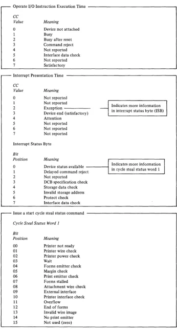
Condition Codes
A condition code is reported to the processor
(1)
at the completion of every Operate I/O instruction and (2) upon presentation of a priority interruption. The condition code is available in the even, carry and overflow bit positions of the Level Status Register (LSR) in the processor. Refer to "Prerequisite Publications" listed in the Preface of this manual for order numbers of the IBM Series/l Processor Unit Description manuals that contain information on the LSR. For commands that do not cause interrupts, the condition code reported after theinstruction is executed is the only status information required or available.
Condition codes reported at the completion of an Operate I/O instruction are:
Condition
Code Meaning
0 Device not attached
1 Busy
2 Busy after reset
3 Command reject
4 Not used
5 Interface data check 6 Not used
7 Satisfactory
Condition Code O-Device Not Attached
Reported when the addressed device is not attached to the system.
Condition Code i-Busy
Reported by the device when it is usable to execute a command because it is in the busy state. The device enters the busy state upon acceptance of a command that requires an interrupt for termination.
It
exits the busy state when the processor accepts the interrupt.Condition Code 2-Busy After Reset
Reported by the printer when it is unable to execute a command because of a reset and the device has not had sufficient time to return to the quiescent state. No interrupt occurs to indicate termination of this condition.
Condition Code 3-Command Reject
Reported by the printer when:
1.
A command is issued that is outside the device command set.2. The device is in an improper state to execute the command.
3. The IDCB contains an incorrect parameter. For example: an odd byte DCB address, or an incorrect function/ modifier combination.
When the printer reports command reject, it does not fetch the DCB.
Condition Code 5-Interface Data Check
Reported by the printer or the channel when a parity error is detected on the I/O data bus during a data transfer.
Condition Code 7-Satisfactory
Reported by the printer when it accepts the command. Condition codes reported during priority interruptions are:
Condition
Code Meaning
0 Not used
1 Not used 2 Exception 3 Device end
4 Attention
5 Not used 6 Not used
7 Not used
Condition Code 2-Exception
This code is reported when an error or exception condition is associated with the interrupt. This condition is
described in the Interrupt Status Byte (ISB) and further described in the 16 bytes of status information.
Condition Code 3-Device End
This code is reported when no error exception or attention conditions occur during the I/O operation. A normal termination of the operation has occurred.
Condition Code 4-A ttention
This code is reported when the printer goes Ready after being in the Not Ready state.
Along with the interrupt condition code, the attachment also transfers an interrupt ID word which provides
Interrupt Identification Word
Acceptance of an I/O interrupt causes the attachment to place an ID word in register 7 (R7) of the interrupted level. For condition code 2, the Interrupt ID word consists of the Interrupt Status Byte (ISB) and the address of the interrupting device. The first byte will be zero for all other condition codes. The format is as follows:
Interrupt ID word
IIB Device address
o
0 0 0 0 0 0 0 0 X X X X X X ~o
7 8 15Interrupt Status Byte
The ISB stores accumulated status information. The format of the ISB is:
O-Device Dependent Status Available I-Delayed Command Reject 2-Not Used
3-DCB Specification Check 4-Storage Data Check 5-Invalid Storage Address 6-Protect Check 7-Interface Data Check
Bit 2 of the ISB is not supported and should always be returned as zero.
Bit O-Device Dependent Status Available Set ON when:
Additional status information (residual address and status bits), is available from the 4974. A Start Cycle Steal Status command must be issued to get this information.
Bit I-Delayed Command Reject Set ON when:
The printer cannot execute a command because of an incorrect parameter in the IDCB.
This bit is only set in the ISB when the attachment is incapable of recording the condition with condition codes during the I/O instruction. The operation in progress is terminated and an interrupt request is generated. Condition code 2 is reported at interrupt accept time. The Residual Address is not revelant to error recovery (see Cycle Steal Status Word 0).
Bit 3-DCB Specification Check Set ON when:
The printer cannot execute the command because a parameter in the DCB is incorrectly specified to perform the desired operation.
Examples: An odd byte chaining address, an odd address for
start cycle steal status, an invalid command in the control word or an incorrect count. Condition code 2 is reported at interrupt accept time. The Residual Address will be the last word of the DCB.
Bit 4-Storage Data Check
Set during cycle steal output operations only. It indicates that the storage location accessed during the current output cycle contained bad parity. The parity in processor storage is not corrected. The attachment issues the status in the ISB and terminates the operation. Condition code 2 is reported at interrupt accept time.
Bit 5-lnvalid Storage Address
Set on as a result of a cycle steal I/O operation when the main storage address presented by the attachment for data or DCB access exceeds the storage size specified on the system. The attachment records the status and terminates the operation. Condition Code 2 is reported at interrupt accept time.
Bit 6-Protect Check Set ON when:
The attachment attempts to access a storage location without the correct storage protect key. (Refer to the IBM Series/l
Model 5 4955 Processor and Processor Features Description,
GA34-002I, or the IBM Series/l Model 3 4953 Processor and Processor Features Description, GA34-0022). The operation is
terminated and condition code 2 is reported at interrupt accept time.
Bit 7-Interface Data Check Set ON when:
A parity error is detected on a cycle steal data transfer. The condition can be detected by the attachment or by the channel. In either case, the operation is terminated and an interrupt is reported to the processor.
Condition code 2 is presented at interrupt accept time (see Figure 2-7 for condition code and status information).
Cycle Steal Status Words
Six bytes of status information are transferred to the processor upon execution of the Start Cycle Steal command. This information has the following format and meaning:
Word , . . - - - .
V Residual address
Device status
Byte 0 I Byte 1
2 f-R~d~ITm;-c~;rt
- I
C;-r~PosWo;
-Byte 0 I Byte 1
3
t
-Form length I Overflow line
4 External interface status
5 Printer interface status
6 Current attachment marks
7 r - - ~y~O_
---t-
_~ytel _ _ _Logical left margin I Logical right margin
V 15
Residual Address- Word 0
o
Operate I/O Instruction Execution Time - - - ,
CC Value
o
1 2 3 4 5 6 7 MeaningDevice not attached Busy
Busy after reset Command reject Not reported Interface data check Not reported Sa tisfactory
Interrupt Presentation Time
CC Value
o
1 2 3 4 5 6 7 Meaning Not reported Not reportedException -Device end (satisfactory) Attention
Not reported Not reported Not reported
Interrupt Status Byte
Bit
Position Meaning
Indicates more information - in interrupt status byte (ISB)
o
1 2 3 4 5 6 7Device status available - - - I
Delayed command reject
Indicates more information in cycle steal status word 1
Not reported
DCB specification check Storage data check Invalid storage address Protect check Interface data check
Issue a start cycle steal status command
Cycle Steal Status Word 1
Bit Position 00 01 02 03 04 05 06 07 08 09 10 11 12 13 14 15 Meaning
Printer not ready Printer wire check Printer power check Wait
Forms emitter check Margin check Print emitter check Forms stalled
Attachment wire check External interface Printer interface check Overflow
[image:26.618.137.484.58.700.2]End of forms Invalid wire image No print emitter Not used (zero)
Device Status- Word 1
When Bit 0 of the ISB is set ON, Device Status word 1 will
further explain the condition that caused the exception
interrupt (CC2). This status will not be reset until the
next Start I/O command. The information in the Device
Status word does not necessarily reflect current status,
but reflects the status at the time of the last non-cycle
steal status interrupt.
Bit O-Printer Not Ready(Disconnect or Power OFF)
The attachment receives no response from the printer when a data wrap sequence is executed. This means the power to the printer is off or the printer signal cable is disconnected. Checking bit 9 (external interface check bit) of Status Word 1 will show which error is occurring.
Bit 0
1
Bit 9
0= Printer Power OFF 1 = Cable Disconnected
The remaining status bits in the device status word may not be valid if bit 0 or bit 9 is on.
Bit I-Printer Wire Check
When a print coil driver is on from 1.6 to 3.0ms, a printer wire check is set, a 24 V regulator is turned off and a printer power check occurs. When the coil driver condition is corrected, the power check is reset.
Bit 2-Printer Power Check
A printer power check is set if the:
• Printer 24V is not within tolerance • Printer 5V is not present
• Printer 10.8V is not within tolerance • Wire check occurred
This bit is reset when the condition causing the wire check is corrected.
Bit 3-Wait
The Wait bit is set if the Mode switch is not in the PRINT position on the printer, and the attachment cannot execute any action command. To determine the completion status of the current command, check the residual line count to see if the forms operation was completed. If it is not zero or the residual address points to the first print character, no
printing has taken place. An exception interrupt will be posted.
Bit 4-Forms Emitter Check
The position of the forms is monitored any time the printer is ready and not in the wait state. As the position is altered, either manually or under program control, the current line position is updated. If the two forms emitters change simultaneously, the current line position cannot be updated properly. If this simultaneous change is detected the forms emitted check is set.
Bit 5-Margin Check
This bit is set whenever the left margin is not detected at the expected time. When a margin check occurs it is possible that the previously printed line was not printed properly. This check may occur after a normal device end interrupt is posted.
Bit 6-Print Emitter Check
This bit is set if the print emitters come too fast or if print emitters are detected out of proper sequence.
Bit 7-Forms Stalled
If the forms should be moving under program control but no movement is detected in the forms emitter in a 250 millisecond period, this bit is set.
Bit 8-Attachment Wire Check
This bit is turned on when the attachment detects an active signal when it should be inactive or when it detects an inactive signal when it should be active.
Bit 9-External Interface Check
Periodically the attachment does a diagnostic checkout of the external cable interface. This check bit is set if: The cable is disconnected, or a grounded or an open signal line eXists, or there is a bad line driver. This condition does not caUse an exception interrupt.
Bit 10- Printer Interface Check
When the printer turns on or off a stepper motor driver line or reset line, it checks to see if the appropriate lines switched on the printer interface. If a line does not switch properly, bit 10 is set.
Bit ll-Overflow
This bit is set if the forms have stopped on the overflow line. If the forms were to move beyond the overflow line there is a residual line count in Device Status word 2. No printing occurs for the current DCB. The residual address can be anywhere in the print line.
Bit 12- End of Forms (EO F)
At the completion of a forms movement operation the forms switch is checked. If the switch is open (indicating no forms), the End of Forms bit is set and an exception interrupt is posted. No printing is attempted when this condition is detected. The EOF condition occurs when there is 1 to 3 inches of paper remaining in the printer.
Note. If a multi-line forms movement command has been given
in the command for which this exception interrupt is given, the amount of paper remaining in the printer may be reduced by the number of lines the command spaced. Print commands must be issued with no spacing in order to print on any of the remaining paper. After all printing is completed, spacing of forms should be executed to provide the operator with a visual indication of the EOF status.
Bit 13-Invalid Wire Image
As characters to be printed are transferred to the print line buffer, they are analyzed to determine if they are valid EBCDIC printable characters. If during this process an invalid sequence of check bytes is detected, the bit is set ON. When printing, if the Wire Image Buffer calls for the same wire to be fired in two adjacent emitter times, the invalid wire image bit is set on and a exception interrupt with a Device Status is posted.
Bit I4-No Print Emitter
This bit is set on if no print emitters are detected when head movement is initiated.
Bit I5-Not used, should be zero.
o
o
Residual Line Count/ Current Position-Word 2
The Residual Line Count (byte 0 of Status word 2) contains the number of lines the forms would have to move to complete the forms control of the last operation. This count is not valid if an error occurred during the transfer of the last DCB. Normally this count is zero.
On an overflow interrupt, if the carriage is to move beyond the overflow line, the
remaining
lines required to be moved to complete the operation are in the Residual Line Count.If
an error such as Forms Stalled occurs during forms movement, thenumber
of lines that remain to be moved to complete the forms operation are in the Residual Line Count.Current forms position (byte 1 of Status word 2) always contains the current line position of the forms. This position will be changed by programmed or manual movement of the forms.
Forms Length/Overflow Line-Word 3
The form length (byte 0 of Status word 3) and the overflow line (byte 1 of Status word 3) are the most recent forms parameters successfully transferred to the printer from the system. If no forms parameters have been transferred, the default values of form length equal to 66 and overflow line equal to 60 will be presented.
External Interface Status- Word 4 See
Note.
Printer Interface Status-Word 5 See
Note.
Current Attachment Marks-Word 6 See
Note.
Logical Left Margin/Logical Right Margin-Word 7 The logical left margin (High Order Byte) and logical right margin (Low Order Byte) represent the boundaries of the characters remaining to be printed when an exception interrupt has terminated a print operation. The logical margin values are equal to the physical print position plus 16. When the print line is transferred from storage, the attachment suppresses unprintable characters and blanks and adjusts the logical margins to reflect the bounds of the printable characters. As printing takes place, the margin from which the printhead is moving will be modified by one, each time a print position is completed.
Note.
Status Word 4, 5, and 6 are used for diagnostic purposes and are not explained in this manual.Status After Power On and Resets
During Power On Reset the following actions occur: • The printer performs Internal Register, Data Flow and
Storage Tests. The printer will remain Busy if these tests fail. If they are successful the printer initializes the Wire Image Buffer which the standard character set and clears all internal buffer locations.
• The forms length is initialized to 66 lines.
• The overflow line is initialized to line 60. The forms are assumed to be positioned on line one.
• The residual address is set to zero.
• The printhead is moved to the left margin if the printer is ready and if the printhead is not already at the left margin.
During System or Device Resets: • Printing and carriage movement stop.
The printer may stop part way through printing a character or spacing a line. If the forms stop between lines, registration will be restored with the next form movement command.
• All pending interrupts are reset. If the printer was in the process of updating the storage access registers (Residual Address) when the reset occurs, the Residual Address may be indeterminate.
During a "Note Ready" condition:
• Printing stops when the current character is completed. • Forms movement is stopped on the current line. • An interrupt is sent to the system with a printer power
Character
A B C D E F
G
H
J K
L
M
N 0 P
Q
R S T
U V
C~':
WX y
Z 0
2 3 4 5
o
Appendix A. EBCDIC Character-Hexadecimal
Equivalent
EBCDIC EBCDIC
(Hex) Character (Hex)
Cl 6 F6
C2 7 F7
C3 8 F8
C4 9 F9
C5 Space 40
C6 ¢ Cent Sign 4A
C7 Period 4B
C8
<
Less than 4CC9 ( Left Parenthesis 4D
Dl + Plus 4E
D2 I Logical OR 4F
D3 & Ampersand 50
D4 Exclamation Point SA D5 $ Dollar Sign 5B D6
*
Asterisk 5C D7 Right Parenthesis 5DD8 Semicolon 5E
D9 I Logical NOT SF E2 - Minus-Hypen 60
E3 Slash 61
E4 Reverse Slant EO
E5 Comma 6B
E6 % Percent 6C E7 Underscore 6D
E8
>
Greater than 6EE9 Question mark 6F
FO Colon 7A
F1 # Number 7B
F2 @ At 7C
F3 Prime Apostrophe 7D
F4 Equal 7E
o
The Forms Tractor Unit is recommended for single-part,
continuous margin punched forms and is required for
continuous multipart and continuous preprinted margin
punched forms.
All forms must meet the following requirements:
Minimum thickness Maximum width Minimum length
Cut Forms
.003 inches 14.5 inches 3.0 inches
Single part cut forms must meet the following requirements:
Maximum thickness Minimum width Maximum length
. 0075 inches 6.0 inches 14.0 inches
Multipart cut forms must meet the following
requirements:
Maximum thickness Minimum width Maximum length Maximum copies
.018 inches 6.0 inches 14.0 inches original plus five
Appendix B. Printer Forms
Continuous Forms
.018 inches 3.0 inches
14.0 inches original plus three Maximum thickness
Minimum width Maximum distance between folds Maximum copies
Maximum forms weight 15 lbs. per ream (6,804 kg)
Remember, when using forms:
Do not use continuous form card stock.
Do not use stapled forms.
Do not use partially separated forms.
Multipart forms should be glued at the top and not crimped .
Printing should be restricted to 0.5 inches from all edges
or folds.
c
C
0
",'1",1 1)1General Description
The purpose of the Wire Image Table (WIT) is to convert an
8-bit code into a wire image pattern. Since the WIT is
loaded from the using system, special characters may be
easily added to the table, or new tables may be generated.
Wire Image Character Pattern Generation
The printer uses an 8 x 7 dot matrix pattern to print its
characters. Seven bytes of data are used to represent the
wire image pattern for each character. Each byte corresonds
to one column of the matrix, starting with byte I as the
leftmost column and bit 0 as the uppermost bit. For
example, an "E" is shown as:
Bits a 1 2 3 4 5 6 7 Bytes
1 2 3 4 5 6 7
x
x
x
x
x
X
X X X
X X
X X X X
Column 1 has bits 0 through 6 on, making its hexadecimal
value FE. Column 2 has no bits on, therefore, its value is
00. Column 3 is represented by a 92, 4 by a 00, 5 by a
92,6 by a 00, and 7 by an 82. The location representing
an "E" within the WIT would contain Hex FE 00920092
0082 as the wire image pattern.
Two rules must be considered when creating characters:
1.
Adjacent dots within a row may not be used. (Adjacent
dots within a column are permissible). Attempting to
use adjacent dots will result in an Invalid Wire Image
check.
2.
No more than 25 dots may be used within anyone
character.
Wire Image Table Structure
The WIT must consist of not less than 512 bytes (64
characters) and not more than 768 bytes (96 characters).
If less than 64 characters are desired, NULL characters
must be used to complete the 64-character set. A NULL
character is defined as one having a wire image pattern of
zero.
Appendix C. Wire Image Table
Each character to be printed requires eight bytes of
data, using the following format:
Bits 0, 1
check bits
Bits 2- 7
displacement field
Bits 8-63
wire image pattern
When a character is to be printed, the user supplies the
8-bit character code. The 4974 uses these eight bits to
access the correct wire image pattern within the WIT.
The entry point into the WIT is determined by the
following formula:
Entry Point
=
8 x
01
alue of bits 2 through 7 of the
specified character code).
The check bits at this address are compared to bits 0
and 1 of the specified character code. If they agree, the
correct point in the table has been reached, and the
character will be printed using the wire image pattern in
bits 8 through 63.
Ifthe check bits do not agree, a new
address will be generated using the displacement field
located at the entry point.
Next Address
=
Entry Point Address
+
8 x (Displacement
Field
+
3)
The check bits at the new address will be compared to
bits 0 and I of the requested character.
Ifthey still do
not agree, the indexing procedure will be repeated using
the new displacement field.
Next Address
=
Previous Address
+
8 x (Displacement
Field
+
3)
A total of four accesses into the table are allowed.
Exceeding this limit will cause an Invalid Wire Image check.
A zero
inthe displacement field indicates no indexing is
to occur. The minimum index possible is four-character
positions.
As an example, consider the standard EBCDIC Wire Image
Table (Figure C-3). Suppose the character to be printed
is a dash. The EBCDIC code for a dash is a hex 60, or 0110
0000. Therefore, the check bits would be 01, and the table
would be accessed at a hex (20 x 8), or hex 0100.
Entry Point
I
I
LocationI
0 0 0 0I
I
I
I
- 1 0 1 0 0
I
0 0 0 0I
I
I
I
I
D F 8 0WIT
Data
[image:34.612.328.560.616.696.2]Bits
a
and 1 at location 0100 are 11, which does not agree with the 01 of the character to be printed. This indicates that you must index to a new location using bits 2 through 7 as your displacement.Next Address
=
0100+
[8 x (IF+
3)]=
0210.WIT
I
LocationI
DataI
o 0 0 0 II
3 D 0 0 0 0 0 0 o 0 0 0 o 0 0 0I
I
I
I
[I
o 1 0 0I
I
D F 8 0 4 0 2 0 1 0 0 8 0 4 0 2I
I
o 2 1 0
I
4 0 1 0 o 0 1 0 o 0 1 0 o 0 1 0j
I
Bits
a
and 1 at location 0210 are 01, indicating that this is the desired character. The wire image patter 10 0010 0010 0010, corresponding to a dash, is printed.Wire Image Table Generation
The following steps should be followed in the generation of a W.I.T.
1. Define the character set.
2.
3.
Each character must be assigned an 8-bit character code and a 7-byte wire image pattern. Only printable characters should be included in the character set. A "space" should not be included.
[image:35.615.34.283.143.274.2]Place the character set into a properly ordered table. Figure C-l is a flowchart of a procedure for ordering the character set into a usable format.
Calculate the Check Bits and Displacement Field for each character in the table. The check bits for each character are simply bits
a
and 1 of the character code. Figure C-2 is a flow chart of a procedure for calculating the displacement fields for the character set ordered in step 2.Note.
If a Table Overflow Error occurs while following the procedure in Figure C-2, the table should be reordered to eliminate any indexes of less than four table positions.Example.
Position 95 indexes to position 96.The table should be reordered as shown below, and the displacement fields recalculated.
Old Order
Table Entry #91
92
93 94 95 96
New Order
Table Entry #91
95 92 93 94 96
o
o
Place character set into ordered table.
Create basic 64 character set
If there is no printable character located at Char. Address, there are three other possibilities having bits 2 through 7 of the character code the same. These three possibilities will be checked and if a printable character is found, it will be stored at the Char. Address. Zero will be stored at the characters' previous address.
Load characters into 256 byte table where character value
=
locationChar. address = 0
Load (char. address)~ X
Yes
Load (char. address
[image:36.612.186.502.80.580.2]+ 192)~X
Figure C-l (Part 1 of 7). Flowchart procedure for formatting a character set
Yes
Load (char. address +
128)--7 X
No
Yes
Store X at char. address
Store zero at char. address +
192
No
Figure C-l (Part 2 of 7). Flowchart procedure for formatting a character set
o
[image:37.612.142.455.52.644.2]c
e
l l. . I"~
Load (char. address
+64)-X
Yes
No
Store X at char. address
Store zero at char. address
+ 128
Store X at char. address
[image:38.620.133.476.53.693.2]Char. address
=
Char. address + 1
[image:39.618.170.439.55.546.2]Basic 64 set is complete.. Remainder of table must now be collapsed into Yes 32 positions.
Table address = 64
Load (char. address)---7 X
No
Yes
0 ,;
, ;'1No
Yes
Load (char. address + 64)-~ X
No
Yes
Store X at table address
[image:40.613.207.456.60.523.2]Store zero at character address + 64
Figure
Related documents
During the first meeting of the class we will discuss how you will choose a Stanford master teacher to observe who is teaching in the Winter Quarter, and seek the teacher’s
Department of Emergency Medicine, Yildirim Beyazit University Medical Faculty; Emergency Service, Atatürk Training and Research Hospital, Ankara, Turkey..
Princeton provost and incoming president Christopher Eisgruber (Appendix A)—in recent written testimony to the Department of Education’s National Advisory Committee on
lithology of ultramafic pyroxenite, mafic gabbro, syenites (alkaline felsic rock), and potassic. granites.Early formed pyroxenite and gabbro both are subalkaline rocks
bearing strength of concrete using steel fibres and silica fume as admixture.. Hence,
the basic super mode field of co-axial fiber and the splice losses spectral variation are.
quality (hardness) of the control samples hardly decreased throughout the entire storage time. These results indicated that non-irradiated kiwifruit did not reach the ripe stage by
The six innovative steps named in this article concentrate on the dual system and its mode of training. Innovations with respect to a swift change of the prevailing
