transmission for scene change
Mengmeng Zhang
1and Huihui Bai
2*Abstract
In view of perfect compatibility with the standard source and channel codec, temporal sampling-based multiple description coding (MDC) has become a better choice for practical applications. However, for the frames change from one scene to another temporal correlation may be destroyed by temporal sampling extremely, which results in the false estimation when the related frames are lost at the side decoder. Therefore, in this article the frames containing scene change are detected and duplicated before temporal sampling, which maintains better temporal correlation in each description. Furthermore, for better rate distortion performance temporal sampling is employed adaptively, that is, frame skipping or up-sampling according to the motion characteristics in original video. The experimental results exhibit better performance of the proposed scheme than other schemes whether in the on–off MDC environment or packet lossy network, especially about 15 dB improvements for the frames with scene change. Therefore, it may be a promising choice for video transmission over error-prone channels, especially over wireless networks.
Keywords:Video coding, Multiple description coding, Temporal sampling
Introduction
In the recent years, the increasing demands for multi-media communication have generated a lot of research interests in developing novel image or video compres-sion technologies. Due to network congestion and delay sensibility, it is always a great challenge for video trans-mission over lossy network. Multiple description coding (MDC) is an attractive approach to solve this problem. It can efficiently combat packet loss without any retrans-mission thus satisfying the demand of real-time services and relieving the network congestion [1].
MDC encodes the source message into several bit streams (descriptions) carrying different information which then can be transmitted over multiple channels. In its simplest form, two parallel channels are assumed to connect the source with the destination. If only one channel works, the descriptions can individually be decoded to sufficiently guarantee a minimum fidelity in the reconstruction at the receiver. However, when both channels work, the descriptions from the channels can be combined to yield a higher fidelity reconstruction.
In the past years, many approaches for realizing MDC have been proposed, such as those using interleaved sca-lar quantizer [2], lattice vector quantizer [3,4], pairwise correlating transforms [5], FEC [6], and so on. Although these methods have shown good performance, they are incompatible with widely used standard codecs, such as H.26x and MPEG-x.
To overcome the limitation, pre- and post-processing-based MDC may be a good choice. In pre-processing, the original source is split into multiple sub-sources be-fore encoding and then these sub-sources can be encoded separately by the standard codec to generate multiple descriptions. The study of [7] is a typical ex-ample, which employs hierarchical B pictures in the H.264/AVC scalable extension [8] for a pre-processing-based MDC. Furthermore, sub-sampling technique can also be applied in pre-processing to realize multiple sub-sources, such as the MD video coder based on spatial sampling [9] and the MD video coder based on temporal sampling [10]. In the method of spatial sampling, through zero padding inside each individual frame, only the correlation of intra-frame is considered to improve side distortion and the temporal correlation of inter-frame is neglected completely. In [10], the method of * Correspondence:[email protected]
2Institute of Information Science, Beijing Jiaotong University, Beijing, China
Full list of author information is available at the end of the article
temporal sampling is proposed to make motion compen-sation interpolation (MCI) more efficient for lost frames, which turns to better rate distortion performance. How-ever, considering the video sequences containing differ-ent scenes, simple MCI method may lead to false interpolated reconstruction at the decoder. Recently, for robust transmission over wireless network, in [11,12] some new MD methods like distributed MDC have been proposed to achieve better rate distortion performance by optimized redundancy allocation for the splitting video sub-sequences.
To address this problem from scene change, a pre-liminary scheme is presented in [13]. Here, in this article an improved MD coding based on adaptive temporal sampling is proposed to make sure the decoder can work correctly when scene changes. According to the temporal correlation in the original video, the frames containing scene change can be detected before temporal sampling. Then, these frames
are duplicated and transmitted over both channels for better side reconstruction. Furthermore, adaptive tem-poral sampling is applied, that is, frame skipping and up-sampling in terms of motion characteristics between the frames, which can achieve better rate distortion performance.
The rest of this article is organized as follows. In the following section, the proposed MD video coding scheme is presented including pre- and post-processing stages and improvement for scene change. The perform-ance of the proposed scheme is examined against
some other relevant MD coders in Section “
Experi-mental results”. We conclude the article in Section
“Conclusions”.
Proposed MDC scheme for scene change
Figure 1 illustrates the proposed MDC scheme for scene change. In the pre-processing stage, scene change is first detected, and then considering the different motion
Figure 1Block diagram of proposed scheme.
information between frames, if the inter-frame motion is enough smooth some frames are skipped to obtain high compression efficiency. On the other hand, if the abrupt motion occurs, the original video sequence is up-sampled to generate a new-length video with adaptively redundant frames. In the post-processing, the corresponding deco-ders should be designed with two main functions. One is down-sampling the decoded video stream to erase the redundant frames. The other is using error concealment methods to estimate lost frames. The details of adaptive temporal sampling and the improvement for scene change are shown in the following subsections.
it is a better solution that the redundancy added should make a tradeoff between the reconstructed quality and compression efficiency. As a result, in the pre-processing stage, the sampling with flexible frame rate is employed to introduce the adaptive redundancy. Since unstable motion appearance of inter-frames will affect the per-formance of error concealment at the side decoder, the rate of sampling should be various according to the mo-tion informamo-tion between any two neighboring frames. More interpolated frames or higher rate of up-sampling will be utilized to smooth the abrupt motion between the frames. On the other hand, if no abrupt motion hap-pens, no redundant frames are needed. Furthermore, if the motion information between continuous frames is enough stable, some middle frames can be skipped to guarantee the high compression efficiency. Such method of pre-processing mainly aims to generate descriptions with regular motion which can make better estimation of lost frames available at the side decoder.
For any two neighboring frames denoted by Fk and
Fk+1, all the motion vectors for each macroblock are
computed and their maximum value can be obtained. Here, it is denoted by kMVkðk;kþ1Þ and kMVkðk;kþ1Þ¼
ffiffiffiffiffiffiffiffiffiffiffiffiffiffiffi
x2þy2 p
((x, y) is the coordinates of the maximal
Figure 3The SCAD values in the test video sequence“merged”.
motion vector). Then, the module kMVkðk;kþ1Þ is com-pared with the threshold T1. If kMVkðk;kþ1Þ<¼T1 ,
some frames may be skipped. But, the number of skipped frames depends on the module of maximal mo-tion vectors betweenFkand the following frames ofFk+1.
At the same time, considering the balance of two channels and better evaluation at side decoder, even frames in the middle are skipped. For example, if kMVkðk;kþ2Þ<¼T1,
MV
k kðk;kþ3Þ<¼T1, and kMVkðk;kþ4Þ>¼T1, then two
frames Fk+1 and Fk+2 are skipped and Fk and Fk+3
are retained for better side reconstruction. Furthermore, if kMVkðk;kþ1Þ>¼T2, the motion between the two
frames is considered unstable so redundant frames are interpolated to smooth such motion information. In view of the balance of two channels, even frames are interpo-lated to maintain equal frame number of two descrip-tions. Consequently, the number of interpolated frames is computed by 2dðkMVk=T21Þ=2e and the
redun-dant frames can be generated using the general algo-rithm of motion compensated interpolation, such as [10].
It is noted that for an original video with N frames if
the mean value of all kMVkðk;kþ1Þ can be computed as
Then the thresholdsT1 and T2 are set empirically as
T1=TandT2= 2T.
In the pre-processing, new interpolated frames and skip some other frames may increase the encoding
computational complexity to some extent. However, the increasing complexity mainly comes from the decision of interpolated or skipped frames. After the simple deci-sion using motion vector, only a few frames need to be interpolated or skipped. Therefore, it cannot lead to higher complexity.
Additionally, the labels (‘O’,‘I’, or ‘S’) are set for each frame to distinguish the original frame, interpolated one, or skipped one, then indexed with odd or even numbers and transmitted over two channels, respectively. Here, the labels are coded by entropy encoder, which nearly can be neglected compared with the total bit rate.
Improvement for scene change
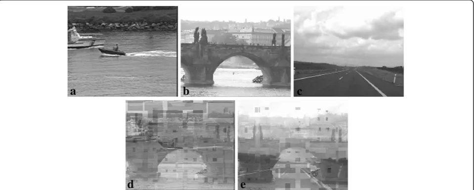
It is noted that the above temporal sampling method is proposed assuming any two neighboring frames are cor-relative in the video. However, considering the video comprised by different scenes, there is no correlation between the last frame in previous scene and the first frame in subsequent scene even if the two frames are neighboring. Here, we design the video sequence
“merged”with three scenes, that is, the first 30 frames of
“coastguard.qcif”,“bridge close.qcif”, and “highway.qcif” as an example, which is shown in Figure 2a–c. If using the simple comparison between kMVkðk;kþ1Þ and the threshold T2, the interpolated frames will be inserted
between two neighboring frames where scene change happens. Obviously, this will lead to substantial quality degradation, as shown in Figure 2d–e.
To address this problem, we must find out where scene change occurs in the video first. Here, we utilize
Figure 5Block diagram of central decoder for packet lossy network.
the sum of compensated absolution difference (SCAD) as the criterion. The value of SCAD can be calculated as follows. Let pkðx;yÞ denote the pixel at the coordinates (x,y) in the current frame Fk-1. And its previous frame
Fk-1can be considered as the reference frame. Then, the
best match block for each block in frame Fk can be
searched in its reference frameFk-1and all the searched
block from frame Fk-1 can be produced as the motion
compensated frameFk0. Therefore, the SCAD can be
cal-culated byXMx ¼1
XN
y¼1pkðx;yÞ p
0
kðx;yÞ, wherep
0
kðx;yÞ is the pixel at the coordinates (x,y) in the motion compen-sated frame Fk0 and the resolution of the video is M×N pixels. Figure 3 shows the statistics of SCAD values for the video“merged”. From Figure 3, the obvious scene changes can be found out at the sharp changes of the curve.
To distinguish the scenes in the video, new marks are needed, that is,‘A’ represents the first frame of a scene
and ‘Z’ represents the last frame. When scene change
appears, both the first and the last frames of the current scene will be transmitted over all channels to ensure the intact rebuilding of frames. Here, take two channels as
example. At the encoder frame Fk-1 and Fk with scene
change will be duplicated and the‘ZZAA’will be labeled at the same time. Then adaptive temporal sampling will
be applied, which is introduced in Section “Adaptive
temporal sampling in pre-processing”. At the decoder, if two channels can work the duplicated frames will be deleted to obtain the central reconstruction. If only one channel works, side reconstruction can be accepted according to the labels.
Adaptive temporal sampling in post-processing
Decoder design for the on–off environment
In the post-processing stage, two situations for decoding should be taken into account, that is, the design of cen-tral or side decoder. Since the two descriptions are gen-erated by odd and even splitting, at the central decoder
Figure 7Comparison between the proposed and conventional scheme.(a) Rate/central distortion performance; (b) Rate/side distortion performance.
the video streams from the standard decoder can be interleaved and realigned in the same way firstly. According to the labels, the interpolated frames can be down-sampled and the skipped frames can be interpo-lated to obtain the central reconstruction. If only one channel works, that is, the side decoder is employed, all the skipped frames with label ‘S’should be interpolated first and reset their labels with‘O’. Then, four possibil-ities exist at the side decoder.
(1) If the current label is‘O’but its following label is‘I’,
the represented frame is just the reconstructed one.
(2) If the current label is‘I’but its following label is‘O’,
the represented frame is the interpolated frame and it can be regarded as the reconstructed one.
(3) If the current label is‘I’and its following label is
also‘I’, the continuous frames represented by‘I’
should be merged to a reconstructed frame.
(4) If the current label is‘O’, and its following label is
also‘O’, a new frame should be interpolated between
the two frames denoted by‘O’.
In Figure 4, a simple example illustrates the pre- and post-processing. The original video sequence has ten frames denoted by F1 to F10. After pre-processing, the
motion-modified video has 16 frames. From the figure, we can see even frames are interpolated adaptively, such
as two frames interpolated between F1 and F2, four
frames interpolated between F4 and F5. At the same
time, even frames are skipped adaptively, such as two
frames F6 and F7 skipped. After splitting by odd and
even frames, the generated descriptions are denoted by video on channel 1 and video on channel 2 and the labels are‘OIOIIOSIO’and‘IOOIISOIO’, respectively. At the receiver, the skipped frames with label‘S’are recon-structed first and reset the labels with ‘O’, so the labels
can be updated as ‘OIOIIOOIO’ on channel 1 or
‘IOOIIOOIO’ on channel 2, respectively. When only
channel 1 works, the reconstruction from side decoder 1 is achieved like the figure. The two interpolated frames between frames 3 and 5 will be merged into a new reconstructed one while a new frame is interpolated be-tween frames 5 and 7 to estimate the lost frame 6. On the other hand, if two channels work, the lossless frames
Figure 9An example of pre-processing for the test video
“coastguard.qcif”: maximal motion vector between frames and the number of interpolated or skipped frames.
except two skipped frames F6 and F7 can be achieved
without the processing by H.264 codec.
Decoder design for packet lossy network
In packet lossy network, due to both descriptions received with packet losses, only central decoder should be designed in post-processing stage and it is different
from the approach in on–off MDC environment.
Figure 5 shows the block diagram of central decoder in packet lossy network. After H.264 decoding, the two gen-erated video sequences are interleaved by odd and even frames to produce a new video data. Then, such video data are processed to obtain central reconstruction.
In post-processing stage, temporal error concealment is first used to reconstruct those lost packets. Since the redundant frames exist, more motion information can be preserved than the conventional scheme, which turns to better reconstruction quality. After temporal conceal-ment, those redundant frames are down-sampled. How-ever, with the increasing of packet loss rate, there are still errors which are difficult to be concealed only by
motion compensation, such as Figure 6a. Furthermore, error propagation will happen when such frames are up-sampled to interpolate skipped ones. As a result, before frame interpolation, spatial error concealment is employed to improve the performance from temporal error concealment. Figure 6b shows obvious visual improvement to substantiate the performance of spatial
concealment. Here, the standard test video “
coast-guard.qcif” is coded at 80 kbps per channel with
packet loss rate 15% per channel.
Experimental results
Performance in on–off MDC channels
Here, there are mainly two experiments taken into account to present the efficiency of adaptive sampling in temporal domain. The first one is shown the better per-formance of the proposed scheme than the conventional scheme without pre-processing stage. In the second experiment, the advantage of the proposed scheme is illuminated compared with the scheme using spatial sampling [9].
In the first experiment, the standard test video“ coast-guard.qcif”is used with 30 frames per second. For a fair comparison, the same mode and parameters are chosen in H.264 encoder and decoder [14].
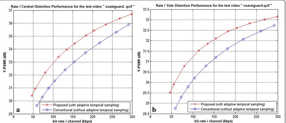
Figure 7 shows the central and side distortion of the proposed scheme against the conventional scheme at the bit rate from 50 to 300 kbps per channel. From the figures, we can clearly see that our proposed scheme can still consistently improve around 0.8–1.5 dB in central distortion and 0.5–1.7 dB in side distortion. Obviously, this is just a global comparison for the whole video. In fact, some individual frames may achieve more advan-tages over the conventional schemes. From Figure 8, the side reconstructed frames by the two compared schemes are presented to illustrate the visual improvements of the proposed scheme at the bit rate 140 kbps.
Figure 9 shows an example of the pre-processing for the standard video sequence“Coastguard.qcif”. From Figure 9, it is shown the maximum values of motion vectors, that
Figure 11Comparison between the temporal-spatial concealment and temporal concealment.(a) 30 kbps, (b) 80 kbps, (c) 180 kbps.
is,kMVks. Here, the threshold T = 1.6003. In the original video “Coastguard.qcif”, according to the pre-processing
mentioned in Section “Adaptive temporal sampling in
pre-processing”, only 30 frames need to be interpolated and 18 frames need to be skipped, which can also be found in Figure 9.
Furthermore, Figure 10 shows the performance com-parison between the proposed scheme and other schemes, such as the scheme in [9] using spatial sampling and the
schemes in [11,12] using distributed MDC. From Figure 10, we can see that compared with the scheme in [9] better rate and central/side distortion perform-ance achieved by the proposed scheme, that is, at the
same bit rate, 1–2 dB improvement in central
distor-tion and 1–3 dB in side distortion. Additionally, com-pared with the schemes [11,12] the proposed scheme
has obtained 0.5–1.5 dB improvement in central
dis-tortion and 1–2 dB in side distortion.
Figure 13Rate-distortion performance.(a) Central quality; (b) side quality.
for all the cases.
First, we validate the effectiveness of the proposed decoder with temporal-spatial concealment. In Figure 11, at the different bit rate 30, 80, and 180 kbps, the decoder with temporal-spatial concealment has better perform-ance than the decoder only with temporal concealment. Especially at the larger packet loss rate, the proposed
scheme has improved around 0.8–1 dB.
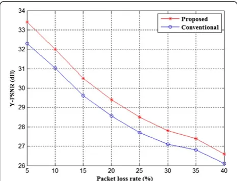
In Figure 12, at the same bit rate 180 kbps, the pro-posed scheme has achieved better performance than the conventional ones. The improvements are brought from 0.6 to 1.1 dB. Note that for low packet loss rate, the improvement is greater. With high packet loss rate, both the proposed scheme and the conventional one cannot do well in error concealment with so many packets lost.
Performance for scene change
Here, the test video “merged” in Section “Proposed
MDC scheme for scene change” is used to exhibit the
better performance of the proposed scheme for scene change. In the proposed one the three scene changes have been taken into account when using adaptive tem-poral sampling while in the compared one scene changes have also been processed only through adaptive tem-poral sampling. For fair comparison, the same method of adaptive temporal sampling has been adopted for the above two schemes.
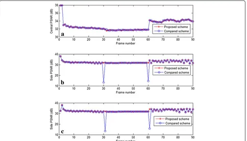
Figure 13 shows the central and side distortion of the proposed scheme against the compared scheme at the bit rate from 50 to 450 kbps per channel. Here, the bit rate means the total bit rate from both channels, the central quality denotes the reconstruction from both channels and the side quality is the average PSNR values from two side decoders. From the figures, we can clearly see that our proposed scheme can still consistently improve around 2–5.5 dB in side distortion although it has a slight decline in the central distortion. Obviously, this is just a global comparison for the whole video. In fact, some indi-vidual frames with scene change may achieve more advantages over the compared scheme. In Figure 14, the proposed scheme has achieved 15 dB improvement per-formance at 240 kbps for the frames with scene change.
Conclusions
In view of perfect compatibility with the standard codec, the MD video coding based on pre- and post-processing may be a better choice in the practical applications. In this article, adaptive frame skipping or up-sampling is
demonstrated superior rate-distortion performance to the conventional MD video coder and spatial sampling-based scheme, which may be a promising choice for video trans-mission over error-prone channels, especially over wire-less networks.
Competing interests
In this article, a novel scheme of multiple description coding and transmission has been proposed based on adaptively temporal sampling, especially for scene change. The experimental results have shown better performance of the proposed scheme than other corresponding schemes whether in the on–off MDC environment or packet lossy network, especially for the frames with scene change.
Acknowledgment
This study was supported in part by the 973 program (2012CB316400), the National Natural Science Foundation of China (Nos. 61103113, 60903066), the Beijing Natural Science Foundation (No. 4102049), the Specialized Research Fund for the Doctoral Program of Higher Education (No. 20090009120006), the Fundamental Research Funds for the Central Universities (No.
2011JBM214), the Jiangsu Provincial Natural Science Foundation (BK2011455) and PHR (IHLB) (PHR201008187).
Author details
1College of Information Engineering, North China University of Technology,
Beijing, China.2Institute of Information Science, Beijing Jiaotong University, Beijing, China.
Received: 27 March 2012 Accepted: 24 July 2012 Published: 21 August 2012
References
1. VK Goyal, Multiple description coding: compression meets the network. IEEE Signal Process. Mag.18(5), 74–93 (2001)
2. V Vaishampayan, S John,Balanced interframe multiple description video compression, 3rd edn. (International Conference on Image Processing (ICIP), Kobe, Japan, 1999), pp. 812–816
3. H Bai, C Zhu, Y Zhao, Optimized multiple description lattice vector quantization for wavelet image coding. IEEE Trans. Circuits Syst. Video Technol.17(7), 912–917 (2007)
4. M Liu, C Zhu, M-description lattice vector quantization: index assignment and analysis. IEEE Trans. Signal Process.57(6), 2258–2274 (2009)
5. AR Reibman, H Jafarkhani, MT Yao Wang, AR Reibman, H Jafarkhani, W Yao, MT Orchard, R Puri, Multiple-description video coding using motion-compensated temporal prediction. IEEE Trans. Circuits Syst. Video Technol 12(3), 193–204 (2002)
6. S Chang, PC Cosman, LB Milstein, Performance analysis of channel symmetric FEC-based multiple description coding for OFDM networks. IEEE Trans. Image Process.20(4), 1061–1076 (2011)
7. C Zhu, M Liu, Multiple description video coding based on hierarchical B pictures. IEEE Trans. Circuits Syst. Video Technol.19(4),
511–521 (2009)
8. ITU-T and ISO/IEC JTC 1,Advanced Video Coding for Generic Audiovisual Services(ITU-T Rec. H.264 & ISO/IEC 14496-10, 2005). Version 4, July 9. D Wang, N Canagarajah, D Redmill, D Bull,Multiple description video coding
based on zero padding(International Symposium on Circuits and Systems (ISCAS), Vancouver, CA, 2004), pp. 205–208
10. H Bai, Y Zhao, C Zhu,Multiple description video coding using adaptive temporal sub-sampling(International Conference on Multimedia and Expo (ICME), Beijing China, 2007), pp. 1331–1334
transmission. EURASIP J. Wirel. Commun. Netw. (2008). Article ID 183536 (2008)
12. A Wang, Z Li, Y Zhao, W Wang, H Bai, Two-description distributed video coding for robust transmission. EURASIP J. Adv. Signal Process.76, 2011 (2011)
13. M Zhang, H Bai,Temporal sampling based multiple description video coding for scenes switching. (Data Compression Conference (DCC), Snowbird Utah, USA, 2012), 413–413
14. ITU-T Rec. H.264 | ISO/IEC 14496-10 AVC,Draft ITU-T Recommendation and Final Draft International Standard of Joint Video Specification(JVT Doc JVT-G050, Joint Video Team (JVT) of ISO/IEC MPEG & ITU-T VCEG(ISO/IEC JTC1/ SC29/WG11 and ITU-T SG16 Q.6) 7th Meeting, Pattaya, Thailand, 2033). 7-14 March
doi:10.1186/1687-1499-2012-265
Cite this article as:Zhang and Bai:Adaptive multiple description video coding and transmission for scene change.EURASIP Journal on Wireless
Communications and Networking20122012:265.
Submit your manuscript to a
journal and benefi t from:
7Convenient online submission 7Rigorous peer review
7Immediate publication on acceptance 7Open access: articles freely available online 7High visibility within the fi eld
7Retaining the copyright to your article