R E S E A R C H
Open Access
A novel sampling synchronization scheme for
OFDM-based system with unified reference clock
Zhuo Sun
*, Tao Peng and Wenbo Wang
Abstract
Due to the constraint of cost and size for mobile wireless communication terminals, many orthogonal frequency division multiplexing (OFDM)-based systems required the same crystal driving the sampling and the channel frequencies, which leads to the challenge of a more comprehensive sampling clock synchronization scheme needed. In this article, the effect of sampling clock error on the system performance was analyzed by dividing it into sampling clock frequency offset (SFO) and sampling timing error (STE) firstly. After that, we proposed a two-stage scheme of sampling clock synchronization based on theoretical derivation: the preliminary SFO was jointly acquired with the carrier frequency offset by using the improved preamble-aided algorithm firstly, the timing drift resulted from residual SFO and STE was tracked based on a phase looped lock in the second stage. The deviation properties of the estimation were achieved theoretically, which reveals that both the estimating variances of SFO and timing drift are in inverse proportion to signal-to-noise ratio and grow linearly by the number of total subcarrier. The results of the simulation show that the proposed synchronization scheme can introduce preferable tracking and robust synchronizing performance for this kind of OFDM-based system.
Keywords:System synchronization, Sampling clock error, Joint estimation, PLL, Timing drift
1. Introduction
Underwater acoustic channels are characterized by se-vere bandwidth limitations, long inter-symbol interfer-ence (ISI) spans, and large Doppler spreads, which lead to significant challengers for reliable communications. Owning to the advantages of high spectral efficiency and robustness against channel fading, orthogonal fre-quency division multiplexing (OFDM) has been applied in modern communication system extensively such as WLAN, WiMAX, LTE, and DVB-T. OFDM is also a good alternative transmission scheme for underwater communication that both remedies the problem of ISI and provides low complexity solutions. However, OFDM is sensitive to inter-carrier interference (ICI) caused by channel variations. Underwater channels vary fast due to the large ratio of the platform motion rela-tive to the sound propagation speed. Even with station-ary transmitters and receivers, significant ICI could still exist due to wave action and water motion. One of the solutions for eliminating ICI is to estimate and correct
the frequency shift adaptively in the synchronization procedure. Therefore, the synchronization scheme for OFDM system used in underwater communications is a critical issue [1].
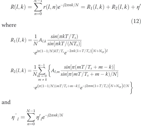
The sampling clock synchronization in an OFDM sys-tem is to mitigate the sampling clock errors due to the mismatch of the crystal oscillators between the trans-mitter and the receiver. The sampling clock error can essentially be divided into two parts: sampling clock fre-quency offset (SFO) and sampling timing error (STE). SFO means the offset of sampling frequency between transmitter and receiver. STE implies that the sampling does not align at the central of the samples, which was also named sampling clock phase offset in some litera-tures [2,3]. The sampling clock error will cause ICI, and a drift in the symbol timing and further worsen ISI [3,4]. The effects of SFO on the system performance are analyzing in terms of BER degradation and ISI in [4,5], respectively.
In the aspect of sampling clock synchronization, there are two different kinds of methods: synchronous pling and asynchronous sampling [6]. Synchronous sam-pling methods [7,8] have large timing fluctuation due to * Correspondence:[email protected]
Key Laboratory of Universal Wireless Communications, Ministry of Education, Beijing University of Posts & Telecommunications, Beijing, China
high-level phase noise when compared with asynchron-ous sampling methods [5,9,10], but the asynchronasynchron-ous sampling methods traditionally needs the interpolation in time domain, which is computationally complex and needs more processing time. Therefore, it cannot be ap-plied to the area where there is a strict requirement on estimation delay time. Moreover, asynchronous sampling method is more sensitive to carrier frequency offset (CFO). A combined SFO and CFO estimation algorithm is presented in [11,12]. However, it has such prerequisite that the timing offset and the initial CFO should been corrected ideally.
In many wireless communication systems, such as WiMAX, there are the constraints of low cost and miniaturization for mobile communication device, and the specification requires that the same crystal must be used to drive the sampling and the channel frequency, which is adopted for many personal handheld terminals (e.g., Smart phone) especially. However, the same reference clock prop-erty introduces a new challenge for the design of joint carrier and sampling clock synchronization, where the quency offsets have relationship with the sampling fre-quency offset besides the Doppler shift. It is seen that most research on joint sampling and frequency synchronization [11-15] have only considered the sampling clock frequency synchronization but ignored the STE. In addition, they view the synchronization of sampling clock frequency all at once whereas neglecting the permanent drift of sampling clock frequency.
In this article, an asynchronous scheme for sam-pling clock synchronization in an OFDM receiver system with the same driving clock source is pro-posed and analyzed: First, the preliminary SFO is jointly acquired with carrier frequency offset by tak-ing the benefit of the same crystal for both sampltak-ing and channel frequencies. Second, by introducing a phase looped lock (PLL) with dynamic adjustable parameters, the timing drift resulted from the re-sidual SFO and STE is tracked and periodically cor-rected. The proposed scheme has not used the interpolation and consequently lowered the computa-tion complexity and processing time consumpcomputa-tion. The requirements of ideal timing offset and the ini-tial CFO are not needed previously because the esti-mation and correction of SFO was jointly deal with CFO and timing error simultaneously.
This article is organized as follows. First, we, re-spectively, analyzed the effect of SFO and STE on the performance of OFDM system in Section 2. After that, we have derived the theoretical solution for the estimation of SFO and timing error in Sec-tion 3. Based on the derivaSec-tion result, a practical es-timation and correction of sampling clock error scheme is proposed in Section 4. The simulation
results and discussion are given in Section 5. Section 6 concludes the article briefly.
2. Analysis of SFO and STE effects on system performance
This section presents the system model and then emphasizes on the analysis of the effect of SFO and STE on the system performance.
The OFDM system model and signal flow are illu-strated in Figure 1. It needs to point out the same crystal drives both the sampling and carrier fre-quency mixing here. As the output of D/A convert-ing, the transmitted OFDM signal during one OFDM symbol duration can be expressed as
s tð Þ ¼X
N1
k¼0
Akej2πkt=ðNTsÞ ð1Þ
where Ak denotes the OFDM symbol on the carrier
k, N is the number of total carrier, and Ts is the
sampling interval for OFDM symbol.
In the following analysis, for the simplicity we assume the transfer function of channel satisfiesH(f) = 1. The s (t) successively passes through the procedures: upper converting onto carrier frequency, additive white Gaussian noise channel, down-converting, then can be written as
r tð Þ ¼s tð Þej2πfctþn tð Þej2πðfcþfcÞt
¼s tð Þej2πfctþn tð Þej2πðfcþfcÞt ð2Þ
In (2), Δfc is the carrier frequency offset between receiver and transmitter, which is caused by Doppler shift and the mismatch between the clock of receiver and transmitter.
Here, we define the A/D sampling interval offset asΔT= Tr–Ts(Tris the sampling interval of A/D converter), and
A/D converter at receiver is t=nTr–Δt,n =0,1,. . .,N–1. The sampled signal can be expressed as
r nð Þ ¼r tð Þjt¼nTrΔt
j is the sample of channel
noise.
Due to the same driving crystal for sampling and channel frequencies, the relationship between SFO and the carrier frequency offset can be denote as
fc quency offset and defined as the ratio of Δfs to sub-carrier spacing. εs is SFO normalized by fs. In (4), the effect of Doppler shift on carrier frequency offset has been neglected.
2.1. STE
We first analyze the effect of STE on the received signal. For the convenience of the following derivation, we as-sume Δfc= 0 and the symbol timing synchronization is already completed. Formula (3) is changed into
r nð Þ ¼X
signal is then transformed into frequency domain
R kð Þ ¼X
arisen from channel noise. By using the summation of geometric sequence, (6) is changed to be
R kð Þ ¼X
When the effect of STE is only concerned, we can let sampling interval offset ΔT= 0. According to that sin x/xapproach to 0 withx→0, the first term in (8) comes to Akexp{−j2πkΔt/(NTs)}, and the second term in (8) equals to 0. Consequently,R(k) is expressed as
R kð Þ ¼Akej2πkt=ðNTsÞþη″ ð9Þ
From (9), it can be seen that the STE will not affect the amplitude of the useful signal, neither introduce ICI. However, the received signal has a phase rotation due to STE, and the angle of phase rotation increases linearly with subcarrier indexk. When considering Δt≤Ts/2, the phase rotation effect is slighter than the effect of symbol timing error. Both the phase rotation from STE and symbol timing error can be corrected in synchronization or channel equalization procedure.
2.2. SFO
In the same way, letΔt= 0 when we analyze the effect of SFO on the received signal, formula (8) can be rewritten as
R kð Þ ¼ 1
The first term in (10) denotes the useful component, which is attenuated and rotated due to the SFO. The sec-ond term represents the interference to thekth subcarrier from other subcarrier, the ICI destroys the orthogonality of OFDM signal and degrade the signal-to-noise ratio (SNR) consequently. The third term is the noise.
For the aims of analyzing the effect of sampling clock synchronization detail, we will extend the above results
to the case of successive OFDM symbols. The nth
sam-ple of thelth OFDM symbol can be deduced from (3)
r lð;nÞ ¼X
N1
k¼0
whereη0l¼n tð Þej2πfct
t¼½ðNþNcpÞlþnTr
, and the sampling
timet=Tr{(N + Ncp)l + n}.
Similarly, the received OFDM signal in frequency do-main is denotes the phase rotation of the kth subcarrier, which have relation with both subcarrier index and OFDM symbol index. Hence, if the SFO is not compensated during several accumulated symbol periods, the degree of phase rotation will increase in the symbol sequence. When the sampling interval offset satisfies ΔT< 0, A/D converter will produce an extra sample for every –Ts/ΔT samples. When the relative sampling interval offset satisfies ΔT> 0, A/D converter will lost a sample for every Ts/ΔT samples, which means the ISI will arise at a later time.
3. Design and theoretical analysis for sampling clock error estimation
Based on the analysis of the effect of sampling clock off-set, this section will elaborate on how to achieve the ac-curate estimation of SFO and STE firstly, then analyze the deviation property of estimation result. Next, the timing drift caused by residual SFO and STE is derived together with performance analysis. On the basis of this, we propose a complete sampling clock synchronization scheme that composed by acquisition stage and tracking stage to realize the estimation and correction of sam-pling clock error.
3.1. Design of training sequence
The preamble-aided estimation is adopted in this article. The preamble is the first symbol of transmission frame, of which the subcarriers are modulated using a boosted BPSK modulation with a specific pseudo noise (PN) code.
Figure 2 gives the structure of preamble sequence in fre-quency domain. Only each third of subcarriers (M = N/3) are modulated with PN sequence, the remainder subcar-riers are filled with zero. It can be proved that this struc-ture of the preamble in frequency domain means three repletion parts in time domain:
C kð Þ ¼C kð þMÞ ¼C kð þ2MÞ;
k¼0;. . .;M1 ð13Þ
where we assume M = N/3 is integer, C(k) is the PN sequence.
The frame period is defined as Ls in sample at trans-mitter, it means the preamble symbol will appear for every Lssamples. The measuring of the frame period at receiver is used in the estimation of timing error in the tracking stage.
3.2. Sampling frequency offset estimation
From (4), the estimation of sampling frequency offset can be translated into the estimation of carrier frequency offset, and the result of carrier frequency estimation can be used to compensate both the sampling frequency off-set and carrier frequency offoff-set.
In general, the relative carrier frequency offset is divided into fractional part and integer part and esti-mated separately
εc¼εF þεI ð14Þ
where εFrepresents the fractional carrier frequency off-set (FCFO) and εIis the integer carrier frequency offset (ICFO).
3.2.1. Fractional carrier frequency offset
Consider the preamble in time domain there are three identical parts, except a phase shift between the adjacent parts caused by the carrier frequency offset. Therefore, estimation of FCFO is based on the idea: if the conjugate of the first part is multiplied by the second part, the ef-fect of channel can be eliminated, and the result is exactly the phase shift.
When neglecting the cyclic prefix, the received OFDM symbol in time domain can be expressed as
r nð Þ ¼X
and n= 0,1,. . .,N – 1. C(k) is the preamble sequence in time domain, and the H(k) is the transfer function on thekth subcarrier. Here, we useεFto represent the over-all carrier frequency offset. It will be proved that the es-timation by the method actually is the fractional frequency offset later.
into (16), then we have
P Mð Þ ¼ej2πεF=3M:A:R
hð Þ0 ð17Þ
From (17), it can be found frequency offset is equal to
εc¼ 3
2π:∠P Mð Þ ð18Þ
The estimation range of frequency offset by (18) is (−3π/2, 3π/2), which means that the offset beyond the range cannot to be calculated using the aforementioned method. Therefore, the fractional carrier frequency offset is mainly achieved here.
The derivation in (16) has not considered the channel noise. If the channel noise exists, then the received sig-nal in (15) will be rewritten as
r nð Þ ¼X
N1
k¼0
C kð ÞH kð Þej2πn kðþεFÞ=Nþw
n ð19Þ
wn is the complex additive white Gaussian noise with
the zero mean and the variance σn2. Similarly in [14], it shows the maximum-likelihood estimation (MLE) of the fractional frequency offset is
^εF ¼tan1fImðP Mð Þ=ReðP Mð ÞÞg ð20Þ
When using the method in [14], the variance ofεFis
Dð Þ^εF ≈ 1
π2M:SNR ð21Þ
The ratio of signal power-to-noise power (SNR) on an OFDM symbol is defined as SNR= Rh(0)A/σn2. Actually,
because the fractional frequency offset is the MLE by (20), it states that the Cramer-Rao bounds are almost met by the estimation with high SNR in [14]. Here, the phase shift is calculated over all of the subcarriers in (16), which usually can satisfy the condition of the high average effective SNR.
3.2.2. Integer carrier frequency offset
The integer carrier frequency offset should be estimated in frequency domain for accurate acquisition. We still achieve the estimation by taking the use of the property of PN sequence and preamble structure.
First, it is known that the PN sequence used for the preamble have the auto-correlation property
Rcð Þ ¼τ M;τ¼i :M
1=M;τ≠i:M
; i¼0;1. . . ð22Þ
We rewrite the value of the kth subcarrier value in received signal in frequency domain as
R kð Þ ¼H kð ÞC kð þεIÞ þW kð Þ ð23Þ
HereW(k) is the FFT conversion ofw(n), which can be proved that W(k) is still a Gaussian variable with the zero mean and variance σn2. We use C(k +εI) to denote that the signal has shiftεIsubcarriers compared to local preamble sequence.
When shifting the local preamble sequence withi sub-carriers, then multiplying withR(k):
Y kð Þ ¼R kð Þ:C kð þiÞ
¼H kð ÞC kð þεIÞC kð þiÞ þW kð ÞC kð þiÞ ð24Þ
As to the second term in (24), since the C(k + i) is a
BPSK modulated symbol with value +1 or −1, the
prod-uct will still hold as the same property of Gaussian vari-ableW(k). Especially, when the shift numberi equals to the existed frequency offsetεI, the (24) will be
Y kð Þji¼εI ¼R kð ÞC kð þεIÞ
¼H kð ÞjC kð þεIÞj2þW kð Þ
¼H kð Þ þW kð Þ ð25Þ
Here, we have used the result |C(k)|2= 1 and elimi-nated theC(k) element in the result.
Next, the correlation function ofY(k) is defined as
Ryð Þ ¼τ
Based on (26), we define a metric of integer frequency offset estimation as
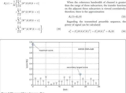
It is not difficult to deduce that the value of |Ry(3)| on the condition ofi =εIis more large than that whilei≠εI. It can be explained as follows. Wheni≠εIthe first term of Y(k) in (24) will be the product of H(k) and random +1/–1, which produces the counteract within the sum of Ry(3). For Ry(0), it actually represents the total power of signal and noise, which is used in (27) for normalizing theM(i).
Figure 3 shows the metric M(i) at different values of shift i, while the SNR is 0 dB. The received signal is assumed without carrier frequency offset. It is showed
that the maximum metric value is achieved at i= 0 as
the predicting, which means the maximum metric appears when there are no subcarrier offset between the received preamble sequence and local sequence.
Therefore, the estimation of integer carrier frequency offset is to find the value ofiwhen satisfying
^εI ¼argmax i
M ið Þ
½ ð28Þ
The following will elaborate on the statistical property ofM(i). First, we rewrite the (26) whilei =εI
Ryð Þ ¼τ 1 M
X N1
k¼0
Hð Þk H kð þτÞ
½
(
þXN1 k¼0
Hð Þk W kð þτÞ
½
þXN1 k¼0
Wð Þk H kð þτÞ
½
þXN 1
k¼0
Wð Þk W kð þτÞ
½
)
ð29Þ
Each term in (29) can be viewed as the arithmetic mean for discrete sequence, when the accumulate number Nis large enough, the arithmetic mean is approximately the statistical expectation. Since the result of linear operation on Gaussian random variable is still Gaussian, the second and third terms in (29) are equal to the mean of Gaussian variable, which both come out zero. The fourth term is the autocorrelation of white Gaussian noise, whose result is an impulse function ofτ. Then, we simplify (29) into
Ryð Þ ¼τ Rhð Þ þτ σ2n:δ τð Þ ð30Þ
where
Rhð Þ ¼τ 1 M
X N1
k¼0
Hð Þk H kð þτÞ
½ :
From (30), we have
Ryð Þ ¼0 Rhð Þ þ0 σ2n ð31Þ
Ryð Þ ¼3 Rhð Þ3 ð32Þ
When the coherence bandwidth of channel is greater than the range of three subcarriers, the transfer function on the adjacent three subcarriers is viewed correlatively; therefore, there is the approximation
Rhð Þ3 ≈Rhð Þ0 ð33Þ
Regarding the transmitted preamble sequence, the power of signal can be calculated
σ2
s ¼E H kj ð ÞC kð Þj
2
¼E H kj ð Þj2¼Rhð Þ0
ð34Þ
0 5 10 15 20 25
0 0.1 0.2 0.3 0.4 0.5 0.6 0.7 0.8
AWGN SNR=0dB
Shift i
score M(i)
maximum score
secondary largest score
Taking (31)–(34) together, we have
It can be deduced that the metric approaches to 1 as SNR increases. The metric value is greater than 0.9 when SNR is above 5 dB, which could be used for verify-ing the result of (28).
3.2.3. SFO
Once the estimation of fractional carrier frequency offset and integer carrier frequency offset are achieved, the sam-pling clock frequency can be calculated using the linear re-lationship with the carrier frequency offset as (4).
^εs¼
fsð^εFþ^εIÞ
fcN
ð36Þ
The method in (36) ignores the existence of Doppler shift in the CFO, so the estimation of SFO is not strict. However, we will deal with amend the estimation in tracking stage.
By now we have already achieved the joint estimation of carrier frequency offset and SFO, but the correction for them should be operated independently. The FCFO offset should be corrected in time domain before the es-timation of ICFO, and the ICFO is estimated in fre-quency domain then fed back into time domain to correct the preamble in next frame. With consideration of the effect of SFO given in Section 2.3, the estimation of SFO is translated into timing error and corrected in frequency domain.
3.3. Timing drift estimation
Except residual sampling clock error, the fractional symbol timing error that may be ignored also contri-butes to the timing drift, which can be considered as a uniform adjustable variable. This adjusting variable is derived in frequency domain and then fed back into time domain to adjust digital oscillator, guaranteeing the synchronization stability. First, we focus on the estima-tion of timing drift.
We assume that the received signal compensated with the estimationεsstill has the timing drift denoted byΔn sampling interval (note it may be decimals), that is
R kð Þ ¼H kð ÞC kð Þei2πkn=NþW kð Þ ð37Þ
When neglecting the noise, (39) only reserves the first term:
Ryð Þ ¼3 Rhð Þ3 ej6πn=N ð40Þ
if the coherence bandwidth of channel is greater than the range of three subcarriers, the transfer functions on the adjacent three subcarriers are viewed relatively, the phase of Rh(3) is approach to 0. Therefore, the timing drift can be estimated as
^
In the following, we will investigate the performance of the estimator by through finding the statistical distri-bution of timing driftΔnand its variance.
In (39), since the conjugate of complex Gaussian
variable W(k) is still a complex Gaussian with the
same expectation and variance, the second and third terms within the summation are independent Gauss-ian variable. Based on the central limit theorem, the
summation of the two terms in terms of k is complex
Gaussian process with distribution N(0, 2σs2σn2), which is expressed as Ne= Nc+ jNs. The imaginary Nc and
real part Ns are independent Gaussian process with
zero mean and variance σs2σn2. The summation of the last term is approximately the autocorrelation of
Gaussian noise and turn to be 0 while τ≠0.
There-fore, Ry(3) in (39) can be rewritten in real and
im-aginary parts separately as
Ryð Þ ¼3 fRhð Þ3 cosð6πn=NÞ þNcg
þj Rf hð Þ3 sinð6πn=NÞ þNsg ð43Þ
and define
Ac¼Rhð Þcos 63 ð πn=NÞ þNc ð44Þ
It is clear thatAcandAsare subject to Gaussian distri-bution according to the property of Gaussian process, and their expectation and variance are
E Að Þ ¼c μc¼Rhð Þcos 63 ð πn=NÞ ð46Þ
E Að Þ ¼s μs¼Rhð Þsin 63 ð πn=NÞ ð47Þ
D Að Þ ¼c D Að Þ ¼s σ2sσ2n ð48Þ
The joint probability density function forAcandAsis
f Að c;AsÞ ¼
It can be seen if we find the statistical property of ϕ, we will get the distribution of estimation ofΔn. By using Jacobiandeterminant
The joint PDF ofGandϕcan be calculated as
f Gð ;ϕÞ ¼j jJ f Að c;AsÞ ð53Þ
Thereby we can get the conditional PDF for ϕ, espe-cially in the condition of high SNR and while ϕis small value, the conditional PDF is
fð Þ ¼ϕ ffiffiffiffiffiffi1
It shows the ϕ is a Gaussian variable with zero mean and varianceσn2/σs2. From (54) we can get the variance of
The result reveals that the variance of timing drift is in inverse proportion to SNR and grows linearly by square of the number of total subcarrier, i.e., the timing drift will be obvious in the condition of either bad channel quality or large subcarrier number.
4. PLL-based two-stage sampling clock estimation and correction scheme
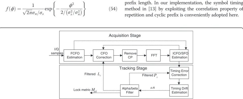
The proposed sampling clock synchronization scheme composed by acquisition stage and tracking stage is illu-strated in Figure 4. The acquisition procedure focuses on the preliminary SFO (carrier frequency offset jointly), of which the fractional part and integer part are handled sequentially. Once the acquisition is completed, it will transfer to tracking stage and no longer return unless the restart of synchronization. In tracking stage, the tim-ing drift is estimated and compensated for each frame by using a PLL. Once locked, the followed samples after correction can be further demodulated.
4.1. Acquisition stage
The processing of acquisition stage includes estimation and correction of FCFO, estimation of ICFO, and cor-recting SFO and CFO at last.
The estimation and correction of fractional carrier fre-quency offset is implemented in time domain. Before that, it is assumed that a coarse symbol timing synchronization is achieved, and then the start position of a frame in sam-ple is already determined with the toleration of ±1/2 cyclic prefix length. In our implementation, the symbol timing method in [13] by exploiting the correlation property of repetition and cyclic prefix is conveniently adopted here.
FCFO
As the first step of overall synchronization process, it need to extract one preamble sequence (Nsamples) from the samples of A/D output based on the result of symbol timing synchronization. Let usePs to denote the starting position of the current frame in received samples. When considering the multipath delay of wireless channel, the actual position should be Ps+ρNcp, and 0≤ρ≤1. The optimum ρ is set with respect to the average multipath delay, when ρ is too greater, the delayed copy of last symbol will result in interference on the current symbol. When ρ is less than the optimum value, it will result in the ICI to next symbol. Certainly, the arbitrary timing error can be compensated in tracking stage.
Second step, by using the method given in Section 3.2.1, we can get the estimation of fractional carrier fre-quency offsetεF, correcting is operated on the extractN samples of the preamble
r0ð Þ ¼n r nð Þ:ej2πnεF=N; n¼0;. . .;N1 ð56Þ
Third step,theNcorrected samples are transferred into fre-quency domain through FFT operation,R(k),k =0,.. .,N–1. According to the method mentioned in Section 3.2.2, the shiftican be found from the maximum metricM(i), which is the estimation of integer carrier frequency offset. Another modified method is to find both the maximum M(i1) and the secondary M(i2). Once the ratio M(i1)/M(i2) exceeds a specific threshold (e.g., 3 in practice) we will takei1as the es-timation of integer carrier frequency offset. The advantage of the latter method is able to avoid the impulsive interference.
Fourth step, as the last step of acquisition stage, is to correct integer carrier frequency offset and the SFO. The integer carrier frequency offset estimated in frequency do-main should be fed back to time dodo-main to correct
r″ð Þ ¼n r0ð Þnej2πnεI=N;
n¼0;. . .;N1 ð57Þ
which is similarly with the way of correction for fractional carrier frequency offset, it should be pointed outr'(n) is the time domain preamble after correction based on (56).
In order to correct the derived SFO in frequency
do-main, the impact stemmed from εsshould be converted
into timing error. While the frame length at transmitter in sample isLs, the estimated frame length at receiver as Lr, then we can give the relationship between the frame length and sampling clock frequency
γ¼Lr
Ls
¼fsþfs
fs
ð58Þ
and the timing error caused by SFO can be derived as
n1 ¼2π 1þNcp=N
γþ1
ð Þ ð59Þ
In the process of extracting the preamble sequence, another two types of timing error also have been intro-duced. Actually, the starting position of the current frame is determined by the starting position of the last frame and the estimated frame length
Ps¼Ps;lastþLr ð60Þ
Base on (60), the achievedPsmay include the fractional part. The integer part ofPsis used to extract the preamble sequence, while the fractional part should be compensated
n2¼2πðPsmod1Þ=N ð61Þ
Another type of timing error is caused by arbitrary delaying the starting position inside cyclic prefix, which is expressed as
n3¼2πNcp:ρ ð62Þ
The three timing errors are corrected together on fre-quency domain samples
R0ð Þ ¼k R kð Þ:ej2πk nð1:lþn2þn3Þ=N;
k¼0;. . .;N1 ð63Þ
where l is the OFDM symbol index in one frame and
the preamble is the first symbol with l= 1. When the
tracking stage is not in the locked state, the preamble is only needed to correct as (63) because the other symbols will not be demodulated currently.
4.2. Tracking stage
Once the processing of acquisition stage finished, the system automatically moves on to tracking stage. In tracking stage, a PLL is used for maintaining the re-ceiver stays time and frequency locked to transmitter. Using the relationship between frequency and timing errors, the PLL initializes the expected frame period. This loop runs from acquisition onwards, adjusting frame timing each frame.
Fifth step, following the acquisition stage, the timing drift is recognized by the method in (42). The estima-tion of timing drift is first used to update the frame period and the starting position of next frame. The compensation scale in one frame should not be too large in case fluctuation happens, the timing drift is used in an alpha (first-order) PLL to track the starting cycle timing of the next preamble, and a beta (second-order) PLL to adjust the local measure of frame period in samples. Therefore, the frame period and starting position of next frame are updated
L0r¼Lrþn:β;0<β≤1 ð64Þ
The alpha and beta PLL filter values are dynamically adjusted according to the phase of tracking stage, which will be demonstrated in Section 5.
Furthermore, since the same crystal clock used for chan-nel frequency and sampling, the timing drift corresponds to the offset of carrier frequency. The carrier frequency offset can be updated
ε0
c¼2π γð 1Þfc=ð Þγfs ð66Þ
The correction will operate on the samples of the next frame based on the updated parameters. The correction process is same as that on the fourth step, except forΔn1 on the fourth step should be replaced by Δn.
Sixth step, after tracking the timing drift for several frames, the PLL will transfer into the steady state to allow the corrected data to be further demodulated. The
0 2 4 6 8 10 12 14 16 18 20
10-6
10-5
10-4
10-3
10-2
10-1
100
SNR(dB)
MSE
Beek algorithm Schmidl algorithm Proposed algorithm
Figure 6Estimation of CFO in AWGN channel.
0 500 1000
-0.03 -0.02 -0.01 0 0.01
Time (frames)
CFO Estimate Error (sub-carriers)
0 500 1000
-1 -0.8 -0.6 -0.4 -0.2 0 0.2
Time (frames)
SFO Estimate Error (ppm)
0 500 1000
-0.2 -0.15 -0.1 -0.05 0 0.05
Time (frames)
CFO Estimate Error (sub-carriers)
0 500 1000
-6 -4 -2 0 2
Time (frames)
SFO Estimate Error (ppm)
lock metric is defined to indicate whether the PLL is locked or not
MPLL¼n:vþMPLL;last:ð1vÞ ð67Þ
where MPLL,last represents the lock metric calculated in last frame, v is the forgetting factor (0 <v≤1). If MPLL exceeds a predefined upper threshold PLL is regarded as locked, and ifMPLLis less than a predefined lower thresh-old it is regarded as losing lock of PLL, then the synchronization system will restart and return back to ac-quisition stage again. The function of the lock metric is es-sentially the timing drift passing through a low pass filter with the transfer function
H zð Þ ¼ v:z
zð1vÞ ð68Þ
which aims at getting a steady value of lock metric. The overall sampling clock synchronization scheme is practically described with the aforementioned six steps processing. It is especially pointed out, in this scheme, that the synchronization of both carrier frequency and sampling clock is recovered thoroughly.
5. Simulation and discussion
The simulation is implemented to evaluate the performance of proposed sampling clock synchronization in AWGN channel and multipath fading channel (ITU V-A channel [16]), the multipath channel has been developed with
Doppler spread of 38.9 kHz. The parameters of OFDM transmission system are as follows: frame length 5 ms, sam-pling clock 22.4 MHz (8 times interpolation), subcarrier spacing of 10.94 kHz with 256 subcarriers. The OFDM sub-carriers are modulated by QPSK, Reed-Solomon, and circu-lar convolution code are used as the outer and inner forwarding error correction scheme with code rate 1/2.
In the simulation process, the forgetting factor is set to 0.125. Four groups of PLL parameters are used for speci-fied number of frames sequentially, and the alpha and beta filter values reduce as the group index increasing: the first group with α= 0.1, β= 0, the second group with α= 0.1, β= 0.0025, the third group with α= 0.05, β= 6.25 × 10⁻⁴
0 2 4 6 8 10 12 14 16 18 20
10-3
10-2
10-1
100
SNR(dB)
MSE
Beek algorithm Schmidl algorithm Proposed algorithm
Figure 7Estimation of CFO in multipath channel.
0 0.5 1 1.5 2 2.5 3 3.5 4 0
0.5 1 1.5 2 2.5 3
x 10-3
SNR(dB)
BER
In AWGN channel In multipath channel
and the fourth group withα= 0.01,β= 2.5 × 10⁻⁵. As the alpha and beta filter values reduce the PLL loses its ability to make large adjustments to the timing, but tracks the training symbol to a great resolution.
Figure 5 depicts the tracking process of SFO in AWGN and multipath fading channel. The simulation is per-formed at SNR 10 dB and normalized SFO 73.728 ppm. In the first 100 number of frames, the PLL is initialized using the first group parameters, of which the beta filter value is set to zero for considering that the timing error is mainly caused by the inaccurate of symbol timing at the begin-ning of synchronization, so sampling clock frequency remains major error. The next two group parameters are used for 100 number of frame sequentially, but during the third 100 frames if the lock metric exceeds a upper thresh-old 1 it will retreat running with the second group para-meters. From Figure 5, it can be seen that the SFO is nearly eliminated after 300 number of frames. Since then the fourth group parameters are bring into use all the time unless the lock metric exceed the threshold 0.1 and go back using the third group parameters.
Because the CFO synchronization in the proposed synchronization scheme is the fundamental algorithm, which affects the performance of overall the synchronization scheme, the proposed CFO synchronization algorithm is compared with another two typical methods of frequency offset synchronization in simulation, the algorithm (Schmidl’s algorithm for short) by using training sequence in [17] and the algorithm (Beek’s algorithm for short) based on the cyclic prefix [18]. For the convenience of analysis of results, the mean square error (MSE) between actual offset and the esti-mation result is adopted. Figures 6 and 7 show the compari-son of three CFO synchronization schemes in term of MSE norm. it can be seen that the proposed scheme achieves about 10–5MSE from 0 dB SNR, which is obviously better than the other two methods.
The BER performance of the proposed synchronization scheme in multipath channel is given in Figure 8. In the simulation, we adopt the method of symbol timing synchronization proposed in [19]. The BER is figured up after the PLL is locked. The simulation result shows that, when using proposed synchronization scheme together with robust QPSK modulation and RS + CC with 1/2 code rate, the BER approach 10–6when SNR≥4 dB. It proved that the proposed sampling clock synchronization scheme can achieve preferable performance for the OFDM system with unified driving crystal.
6. Conclusion
Regarding the requirement of miniaturization and low cost for wireless personal communication device, on which the same crystal to drive the sampling and channel frequency is equipped generally. The proposed scheme of sampling clock synchronization is perfectly appropriate for this kind
of OFDM-based communication system. One of the advan-tages of the scheme is that it needs not an accurate result of symbol timing synchronization (only with the toleration of ±1/2 cyclic prefix length). This scheme also has the ad-vantage of low complexity that has been verified on a multi-core DSP platform for a wireless system in author’s research work.
Competing interests
The authors declare that they have no competing interests.
Acknowledgments
This study was supported by the National Science and Technology Major Projects under grant 2012ZX03003011 and 2012ZX03003007, and the BUPT Research Innovation Project under grant 2011RC0111.
Received: 20 September 2012 Accepted: 6 November 2012 Published: 23 December 2012
References
1. SF Mason, CR Berger, SL Zhou, P Willett, Detection, synchronization, and Doppler scale estimation with multicarrier waveforms in underwater acoustic communication. IEEE J. Sel. Areas Commun.
26(9), 1638–1649 (2008)
2. DK Kim, SH Do, HB Cho, HJ Chol, KB Kim, A new joint algorithm of symbol timing recovery and sampling clock adjustment for OFDM systems. IEEE Trans. Consum. Electron.44(3), 1142–1149 (1998)
3. BG Yang, KB Letaief, S Roger, Timing recovery for OFDM transmission. IEEE J. Sel. Areas Commun.18(22), 2278–2291 (2000)
4. T Pollet, P Spruyt, M Moeneclaey, The BER performance of OFDM systems using nonsynchronized sampling, inProceeding of IEEE Globecom’94, vol. 1, San Francisco(1994), pp. 253–257
5. J Kim, EJ Powers, Y Cho, A nonsynchronized sampling scheme, inthe 36th Asilomar Conference on Signals, Systems and Computers, vol. 2, Pacific Grove, CA(2002), pp. 1900–1904
6. AI Bo, Y Shen, ZD Zhong, BH Zhang, Enhanced sampling clock offset correction based on time domain estimation scheme. IEEE Trans. Consum. Electron.57(2), 696–704 (2011)
7. BG Yang, KB Letaief, RS Cheng, ZG Cao, An improved combined symbol and sampling clock synchronization method for OFDM systems, in Proceedings of the 1999 IEEE Wireless Communications and Networking Conference, vol. 3, New Orleans(1999), pp. 1153–1157
8. DW Paranchych, NC Beaulieu, Performance of a digital symbol synchronizer in co-channel interference and noise. IEEE Trans. Commun.
48(11), 1945–1954 (2000)
9. BG Yang, MA ZhengXin, CAO ZhiGang, ML-oriented DA sampling clock synchronization for OFDM systems, inProceedings of the International Conference on Communication Technology, vol. 1, Beijing(2000), pp. 781–784
10. FJ Harris, M Ric, Multirate digital filters for symbol timing synchronization in software defined radios. IEEE J. Sel. Areas Commun.
19(12), 2346–2357 (2001)
11. D Wang, AQ Hu, A combined residual frequency and sampling clock offset estimation for OFDM systems, inIEEE Asia Pacific Conference on Circuits and Systems, vol.1, Singapore(2006), pp. 1184–1187
12. WD Xiang, T Pratt, A simple cascade carrier frequency and sampling clock offsets estimation method for OFDM systems, inFirst IEEE Consumer Communications and Networking Conference, vol. 1, Las vegas(2004), pp. 718–720
13. H Lee, J Lee, Joint clock and frequency synchronization for OFDM-based cellular systems. IEEE Signal Process. Lett.18(12), 757–760 (2011) 14. E Del Castillo-Sanchez, F.J. Lopez-Martinez, E. Martos-Naya, J.T.
Entrambasaguas, Joint time, frequency and sampling clock synchronization for OFDM-based systems, inWireless Communications and Networking Conference, vol. 1, Budapest(2009), pp. 1–6
16. ITU-R M.1225,Guidelines for evaluation of radio transmission technologies for IMT-2000[S](1997). www.itu.int
17. TM Schmidl, D.C. Cox, Robust Frequency and timing synchronization for OFDM. IEEE Trans. Commun.45(12), 1613–1621 (1997)
18. PH Moose, A technique for orthogonal frequency division multiplexing frequency offset correction. IEEE Trans. Commun.10(42), 2908–2914 (1994) 19. JJ Van De Beek, M Sandell, PO Borjesson, ML estimation of time and
frequency offset in OFDM systems. IEEE Trans. Signal Process. 45(7), 1800–1805 (1997)
doi:10.1186/1687-1499-2012-368
Cite this article as:Sunet al.:A novel sampling synchronization scheme for OFDM-based system with unified reference clock.EURASIP Journal on Wireless Communications and Networking20122012:368.
Submit your manuscript to a
journal and benefi t from:
7Convenient online submission
7Rigorous peer review
7Immediate publication on acceptance
7Open access: articles freely available online
7High visibility within the fi eld
7Retaining the copyright to your article