DYNAMIC MODELING AND VIBRATION ANALYSIS
OF A BALL-SCREW DRIVE SYSTEM
Saeed Asiri
1, Hamza Diken
21,2
Mechanical Engineering Department, King Abdulaziz University, Jeddah, SA
ABSTRACT
Many of the papers studying the screw-drive system dynamic model concentrated on the control methodologies
that is why vibrational models are either simple lumped models or simplified flexible beam models. In this paper
a screw-drive system dynamic model and its vibrations are discussed. The screw is considered as an
Euler-Bernoulli type flexible beam with fixed-free boundary conditions and the table inertia is considered as a moving
force on the screw. First three modes of the longitudinal and torsional vibration of the flexible screw are
extracted. The table travels with a triangular velocity motion profile. Table vibrations are studied with respect
to the ratio of the table mass to the screw mass and the screw length.
Keywords:Screw-Drive System, Vibration, Continuous System, Elastic Shaft, Moving Force
I. INTRODUCTION
Demands for increased productivity and higher part quality have motivated a significant amount of research
dedicated to developing faster and more accurate feed drive systems. Gu and Cheng (2004) studied the dynamic
response of a high-speed spindle subject to a moving mass. The system consists of a ball screw and a moving
nut. The ball screw is modeled as a high-speed rotating shaft using Timoshenko beam theory and the nut is
modeled as a moving concentrated mass. Varanasi and Nayfeh (2004) developed a model of lead-screw system
dynamics that accounts for the distributed inertia of the screw and the compliance and damping of the thrust
bearings, nut, and coupling. The distributed-parameter model of the lead-screw drive system is reduced to a
low-order model using a Galerkin procedure and verified by experiments performed on a pair of ball-screw systems.
Kim and Chung (2006) modeled the feedback and feed-forward controllers described in discrete-time domain
which are incorporated in the motion controller. Design requirements of the servomechanism such as stability,
geometric errors, resonance of the driving mechanism, deformation of the structure, actuator saturation are
described. Ouyanga and Wang (2007) presented a dynamic model for the vibration of a rotating Timoshenko
beam subjected to a three-directional load moving in the axial direction. The model takes into account the axial
movement of the axial force component. The bending moment produced by this component acting on the
surface of the beam is also included in the model. Kamalzadeh and Erkorkmaz (2007 and 2007) presented a
precision control strategy for ball screw drives. Axial vibrations are modeled and actively compensated in the
control law, which enables the realization of high positioning bandwidth. Lead errors, arising from
imperfections of the screw, are modeled and removed from the loop by offsetting their effect from the command
trajectory and position feedback signals. Zhou et al. (2007) studied dynamic behaviors of free torsional
vibrations of lead-screw feed drives using the finite element method considering of changeable table position
L
t m
motor
) ( 2 ) ( )
(t ut l t
x
following and disturbance rejection performance of the controller at selected frequencies by the use of adaptive
feedforward cancellation method.Vicente et al. (2012) presented in their work a high-frequency dynamic model
of a ball screw drive. The analytical formulation follows a comprehensive approach, where the screw is modeled
as a continuous subsystem, using Ritz series approximation to obtain an approximate N-degree-of-freedom
model. Gordon and Erkorkmaz (2013) studied a pole-placement technique to achieve active vibration damping,
as well as high bandwidth disturbance rejection and positioning in ball screw drives.
Models in the papers of Gu and Cheng (2004) and Ouyanga and Wang (2007) consider rotating Timoshenko
beam having a moving mass with constant velocity. Lateral deflections of the screw-mass system are studied.
Varanasi and Nayfeh (2004) models screw as a continuous beam with longitudinal and torsional vibrations but
the system reduced to a low-order model to analyze the system dynamics. Kim and Chung (2006) models the
system as two disks attached to each other with torsional spring and the table mass is attached to the moving
disk with a linear spring. In the papers of Kamalzadeh and Erkorkmaz (2007), Kamalzadeh and Erkorkmaz
(2007), Hossainkhani and Erkorkmaz (2012), and Gordon and Erkorkmaz (2013) screw-drive system is modeled
as two masses separated by a linear spring. Zhou et al. (2007) models the screw torsional vibration with finite
element modeling. Vicente et al. (2012) models the screw as a continuous beam with longitudinal and torsional
vibration but only some fixed table positions are considered.
In this paper the screw is modeled as a rotating Euler-Bernoulli beam for longitudinal and torsional vibrations.
Table mass is assumed traveling according to a triangular velocity time function. Table inertia is considered as a
moving load on the rotating screw. Normal modes of a constrained structure method is used to find dynamic
equations of the motion, first three modes of the longitudinal and torsional vibration are considered, table mass
vibrations during the travel are studied.
II. SYSTEM MODELING
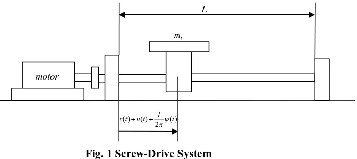
Fig. 1 shows the model of the ball-screw drive. The system consists of a screw of length L, electrical motor and
bearings to support the screw and a table.
Fig. 1 Screw-Drive System
Table is guided not to have lateral motions, friction between screw and nut and table and guide are assumed
(1)
Here is the travel length of the table and T is the total travel time. Since the table is accelerating and
decelerating during its motion, rotating screw will experience a force because of the table inertia. The screw is
assumed a continuous shaft and it will have longitudinal and torsional vibrations under the table inertial force
and motor torque. Longitudinal and torsional vibration of the screw is assumed as,
(2)
Since there is a table with a mass moving on the screw, the screw can be considered as a constrained structure.
The generalized coordinates of the screw for longitudinal vibration can be calculated from; Thomson (1981)
(3)
is the viscous damping ratio, is the th longitudinal natural frequency of the screw, is the generalized
mass which is,
(5)
Here is the mass per unit length of the screw. Total motion of the table is the sum of the prescribed table
motion of plus longitudinal vibration of the table and plus the table motion because of the screw
torsional vibration.
(6)
Here l is the lead of the screw as meter per rotation. Then the inertial force acting on the screw because of the
table mass will be
(7)
Table motion in terms of the generalized coordinates and normal modes is
(8)
(9)
When the equation (9) is put into the equation (7) and used in the equation (3), the following dynamic equation
for the generalized coordinates of the longitudinal vibration will be obtained.
(10)
Similar equation will be obtained for the generalized coordinates of the torsional vibration. In this case table
mass inertial force that is converted to a torsion acting on the screw will be used.
(11)
First three modes of the longitudinal and torsional vibrations are assumed. In this case equations (10) and (11)
will provide six coupled equations of the motion for the generalized coordinates. When the equations are
arranged in matrix form we will have
(12)
The vector is . Elements of the mass, the damping and the stiffness matrices are
given in appendix. Torsional and longitudinal vibration modes of the screw are calculated assuming fixed-free
flexible beam boundary condition;
(13)
Longitudinal natural frequencies of a fixed-free beam are given as
Here E is the elasticity modulus is the material density and L is the screw length. Torsional natural
frequencies of the screw are
(15)
Here is the shear modulus.
III. RESULTS AND DISCUSSIONS
Parameters used for the numerical calculations are given in Table 1. The screw is 1.5 m long and has 20 mm
diameter. Its mass is 3.6 kg. First three longitudinal natural frequencies of the screw are 849.4 Hz, 2548.2 Hz
and 4247.1 Hz. First three torsional natural frequencies of the screw are 537.2 Hz, 1611.6 Hz and 2686.1 Hz. It
is assumed that screw table travels with the triangular velocity function which is described in the equation (1)
Table 1 List of Parameters
Description Screw
length
Lead Screw
diameter
Screw
mass
Material
density
Elasticity
modulus
Shear
modulus
Damping
ratio
Travel
length
Symbol L l d ms E G Lt
Value 1.5 m 0.005
m/rev
0.02 m 3.6 kg 7700
kg/m3
200 GPa 80 GPa 0.02 1.0 m
Screw table has a length of 50 cm that is why the travel length is 50 cm less than the screw length. Travel time is
assumed as 2 seconds. Fig. 2, Fig. 3 and Fig. 4 are showing the first, second and third mode longitudinal
vibrations separately.
0 0.2 0.4 0.6 0.8 1 1.2 1.4 1.6 1.8 2
-4 -2 0 2 4 6 8
10x 10
-7
Travel time [s] ul1
[
m
]
Fig. 2 First Mode Longitudinal Vibration.
L=2 m, T=2 s, mt=20 kg.
0 0.2 0.4 0.6 0.8 1 1.2 1.4 1.6 1.8 2
-6 -4 -2 0 2 4 6 8
10x 10
-8
Travel time [s] ul2
[
m
]
Fig. 3 Second Mode Longitudinal Vibration.
L=2 m, T=2 s, mt=20 kg.
In the first half of the travel, screw table has positive, in the second half of the motion has negative constant
valued acceleration. Table inertia acts to the screw like a pushing force in the first half of the motion in the
second half like a pulling force.
Fig. 2, Fig. 3 and Fig. 4 show this effect. In the beginning of the motion, the screw has vibration in the negative
direction and this vibration is damping out before the second half motion starts. Since the vibrating length of the
Fig. 5 shows the vibration amplitudes of the table when the three longitudinal modes considered together. Fig. 6,
Fig. 7 and Fig. 8 show the first three torsional mode vibrations of the screw separately.
0 0.2 0.4 0.6 0.8 1 1.2 1.4 1.6 1.8 2
-6 -5 -4 -3 -2 -1 0 1 2 3
4x 10
-8
Travel time [s] ul3
[
m
]
Fig. 4 Third Mode Longitudinal Vibration.
L=2 m, T=2 s, mt=20 kg.
0 0.2 0.4 0.6 0.8 1 1.2 1.4 1.6 1.8 2
-4 -2 0 2 4 6 8
10x 10
-7
Travel time [s] ul
[
m
]
Fig. 5 Total Longitudinal Vibration.
L=2 m, T=2 s, mt=20 kg.
0 0.2 0.4 0.6 0.8 1 1.2 1.4 1.6 1.8 2
-1 -0.5 0 0.5 1 1.5 2
2.5x 10
-6
Travel time [s] ut1
[
ra
d
]
Fig. 6 First Mode Torsional Vibration.
L=2 m, T=2 s, mt=20 kg.
0 0.2 0.4 0.6 0.8 1 1.2 1.4 1.6 1.8 2
-2 -1.5 -1 -0.5 0 0.5 1 1.5 2
2.5x 10
-7
Travel time [s] ut2
[
ra
d
]
Fig. 7 Second Mode Torsional Vibration.
L=2 m, T=2 s, mt=20 kg.
0 0.2 0.4 0.6 0.8 1 1.2 1.4 1.6 1.8 2
-6 -5 -4 -3 -2 -1 0 1 2 3
4x 10
-8
Travel time [s] ut3
[
ra
d
]
Fig. 8 Third Mode Torsional Vibration.
L=2 m, T=2 s, mt=20 kg.
0 0.2 0.4 0.6 0.8 1 1.2 1.4 1.6 1.8 2
-1 -0.5 0 0.5 1 1.5 2
2.5x 10
-6
Travel time [s] ut
[
ra
d
]
Fig. 9 Total Torsional Vibration.
0 0.2 0.4 0.6 0.8 1 1.2 1.4 1.6 1.8 2 -1.5 -1 -0.5 0 0.5 1 1.5 2 2.5 3 3.5x 10
-6
Travel time [s]
ult
[
m
]
Fig. 10 Total Torsional And Longitudinal
Vibration.
L=2 m, T=2 s, mt=20 kg.
0.5 1 1.5 2
0 0.2 0.4 0.6 0.8 1 1.2 1.4x 10
-5
Travel time [s]
To ta l ta b le v ib ra ti o n [ m ] =4 =5 =6
Fig. 11 Total Table Vibration Versus Travel Time
L=1 m.
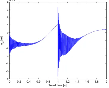
Vibration trends of the torsional motion are similar to the ones of the longitudinal vibrations because the modes
are same for the longitudinal and torsional vibrations for a fixed-free beam but the torsional vibration
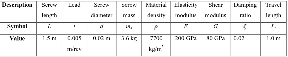
amplitudes are much higher than the longitudinal vibration amplitudes for the given example. Fig. 9 shows the
torsional vibration amplitudes if the three modes are combined. Fig. 10 shows total vibration amplitudes of the
table if the longitudinal and torsional vibrations of the screw are considered together. Fig. 11 shows total table
vibrations for different travel times and for different table mass to screw mass ratios. When the mass ratio is
increased, table inertia increases. Vibration amplitudes versus travel time curves are having exponential decay
character. For longer travel times, the vibration amplitudes are also merging to each other and the effect of table
mass inertia becomes negligibly small. Fig. 12 shows table vibration amplitudes for the screw lengths of 2
meters.
0.5 1 1.5 2
0 0.5 1
1.5x 10
-4
Travel time [s]
To ta l ta b le v ib ra ti o n [ m ] =4 =5 =6
Fig. 12 Total Table Vibration Versus
Travel Time. L=2 m.
1 1.1 1.2 1.3 1.4 1.5 1.6 1.7 1.8 1.9 2
0 0.2 0.4 0.6 0.8 1 1.2x 10
-4
Screw Length [m]
To ta l ta b le v ib ra ti o n [ m ]
Tt=0.5
Tt=1.0
Tt=1.5
Fig. 13 Total Table Vibration Versus Screw
Length. mt=20 kg.
Fig. 13 shows the table vibration amplitude with respect to a fixed screw length but for different travel times.
For longer screw and shorter travel time vibration amplitudes are exponentially increasing.
IV. CONCLUSION
In this paper a screw-drive system vibration model is studied. The screw is modeled as a Euler-Bernoulli type
flexible beam with fixed-free boundary conditions. The table inertia is considered as a moving force on the
with a triangular velocity motion profile. Table vibrations are studied for different table mass to screw mass
ratios and also for different screw lengths.
REFERENCES
[1]. Gu UC, Cheng CC, "Vibration analysis of a high-speed spindle under the action of a moving mass".
Journal of Sound and Vibration, Vol(278), pp. 1131-1146, 2004.
[2]. Varanasi KK and Nayfeh SA, "The dynamics of lead-screw drives: low-order modeling and experiments",
Journal of Dynamic Systems, Measurement, and Control, Vol(126), pp. 388-396, 2004.
[3]. Kim MS and Chung SC, "Integrated design methodology of ball-screw driven servomechanisms with
discrete controllers", Part I: Modeling and performance analysis. Mechatronics Vol. 16, pp. 491–502,
2006.
[4]. Ouyang H and Wang M, A dynamic model for a rotating beam subjected to axially moving forces. Journal
of Sound and Vibration, Vol(308), pp. 674-682, 2007.
[5]. Kamalzadeh A and Erkorkmaz K, "Compensation of axial vibrations in ball screw drives", Annals of the
CIRP, Vol(56), pp. 373-378. 2007
[6]. Kamalzadeh A and Erkorkmaz K, "Accurate tracking controller design for high-speed drives",
International Journal of Machine Tools & Manufacture, Vol(47), pp. 1393–1400, 2007
[7]. Zhou Y, Peng F and Chen J, "Torsion vibration analysis of lead-screw feed drives with changeable table
position and work-piece mass", Proceedings of the 2007 IEEE International Conference on Mechatronics
and Automation, pp. 2194-2199, 2007.
[8]. Hosseinkhani Y and Erkorkmaz K, "High frequency harmonic cancellation in ball-screw drives". Procedia
CIRP Vol(1), pp. 615 – 620, 2012
[9]. Vicente DA, Hecker RL, Villegas FJ and Flores GM, "Modeling and vibration mode analysis of a ball
screw drive", International Journal of Advanced Manufacturing Technology, Vol(58), pp. 257–265, 2012.
[10].Gordon DJ and Erkorkmaz K, "Accurate control of ball screw drives using pole-placement vibration
damping and a novel trajectory prefilter". Precision Engineering 37, pp. 308– 322, 2013.