SOURCE RECTIFIER WITH BATTERY CHARGING
CAPABILITY IN REGENERATIVE MODE OF SRM
M.Rajesh
1, M.Sunil Kumar
2 1P.G.Student,
2Asst.Prof, Dept.of Eee, D.V.R & Dr.H.S Mic College of Tech, Kanchikacharla
ABSTRACT
In this paper, a two-stage power converter based on current source rectifier (CSR) is proposed to improve the
power factor of Switched Reluctance Motor (SRM) drives and Battery Charging Capability in Regenerative
Mode. CSR stage in the input of SRM converter, eliminate dc link's capacitors and create the capability of
energy saving in regenerative operation mode of SRM drives. The space-vector modulation (SVM) is used in the
CSR switching. The validity and effectiveness of the proposed approach is shown by simulation, also it is
verified experimentally by using a laboratory 4-KW SRM setup based on TI TMS320F2812 platform. The results
demonstrate a good agreement with the required conditions
I. INTRODUCTION
Power electronic converters can be broadly classified as AC-DC, AC-AC, DC-AC and DCDC converters. The
focus of the work presented in this thesis is in the AC-DC conversion area. Most AC-DC converter applications
desire a constant DC output voltage which will be further used for other purposes. Till very recently the
attention of all manufacturers and users of AC-DC converters was on the DC side of the same. In this sense, the
most popular AC-DC converter is the rectifier with C filter at lower power levels and the phase-controlled
rectifier with LC filter at higher power levels. Currently, the concern in rectifiers include power quality issues
relating to the source end as well. The reason for this is the undesirable AC line current harmonics drawn from
the utility by the standard rectifiers. The presence of harmonics in the line current results in the distortion of the
voltage at the Point of Common Coupling (PCC) due to the presence of source inductance. This may cause
malfunction of other loads, power system protection and monitoring devices. Some of the other problems caused
by line current harmonics are, overheating of the neutral line, interference with communication and control
signals etc. With presence of lower-order harmonics in input current, power factor comes down. Poor power
factor of operation implies interactive use of the volt-ampere rating of the utility equipment.
The power factor is defined as the ratio of the average power to the apparent power at an AC terminal.
Assuming an ideal sinusoidal input voltage source, the power factor can be expressed as the product of two
factors, the distortion factor and the displacement factor. The distortion factor kd is the ratio of the fundamental
root-mean-square (RMS) current to the total RMS current. The displacement factor kq is the cosine of the
Power factor correction is the method of improving the power factor of a system by using suitable devices. The
objective of power factor correction circuits is to make the input to a power supply behave like purely resistive
or a resistor. When the ratio between the voltage and current is a constant, then the input will be resistive hence
the power factor will be 1.0.
II. SWITCHED RELUCTANCE MOTOR
Switched Reluctance Motors (SRM) have inherent advantages such as simple structure with non-winding
construction in rotor side, fail safe because of its characteristic which has a high tolerances, robustness, low cost
with no permanent magnet in the structure, and possible operation in high temperatures or in intense temperature
variations. The torque production in switched reluctance motor comes from the tendency of the rotor poles to
align with the excited stator poles. The operation principle is based on the difference in magnetic reluctance for
magnetic field lines between aligned and unaligned rotor position when a stator coil is excited, the rotor
experiences a force which will pull the rotor to the aligned position. However, because SRM construction with
doubly salient poles and its non-linear magnetic characteristics, the problems of acoustic noise and torque ripple
are more severe than these of other traditional motors. The Switched Reluctance Motors is an electric machine
that is characterized mainly by its constructive simplicity. It has salient poles on both stator and rotor and its
magnetic core consists of laminated steel. It is a doubly salient, single excited motor. Each stator pole has a
simple concentrated winding and there are no conductors of any kind on the rotor which makes the construction
cheaper, reliable, and rugged.
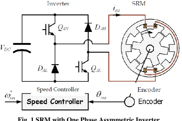
Fig. 1 SRM with One Phase Asymmetric Inverter
The number of poles on the SRM’s stator is usually unequal to the number of the rotor to avoid the possibility of
the rotor being in a state where it cannot produce initial torque, which occurs when all the rotor poles are aligned
with the stator poles. Fig.1 shows a 8/6 SRM with one phase asymmetric inverter. This 4-phase SRM has 8
stator and 6 rotor poles, each phase comprises two coils wound on opposite poles and connected in series or
parallel consisting of a number of electrically separated circuit or phases. These phase windings can be excited
rectifier diodes with advantage of improving low power factor and eliminating high input line harmonics
(Current Source Rectifier). Phase winding energizing is done by machine side converter as second stage [6, 7].
The CSR in modified SRM drive have six bidirectional self-commutated switches. No short circuit must be
applied to the mains filtering capacitors and No open circuit must be applied to the output current.
The reference current vector can be realized by using the two limiting active vectors of the sector. The resulting
output line-voltage space vector defined by:
(3.1)
Where . The switching technique applied to the CSR is space vector modulation (SVM)
expressing the required instantaneous input current vector according to the voltage vector. Unit power factor
will be achieved through this approach. The switching state vectors duty cycles are:
(3.2)
Where mc is the modulation index, TS is the sampling interval and sc θ is the angle between the reference
vector and the first active vector [8].
III. SIMULATION DIAGRAM AND RESULTS
The performance of the proposed method is demonstrated in simulation and experimentally using a 4-KW SRM
drive that a dc machine is mechanically coupled to it. The experimental setup is based on fixed- point
TMS320F2812 board as a suitable choice for implementing motor controllers applications and executing the
control algorithm. The current control is implemented by a closed-loop control with hysteresis switching control
of the converter. The SRM rotor position is obtained from an optical encoder which is installed on the rotor
shaft. The SRM drive system is conducted on a partial load. The current reference is 3 (A).
Fig 3: Simulation Result for Input Voltage and Current
Fig 4: Simulation Waveform for Power Factor
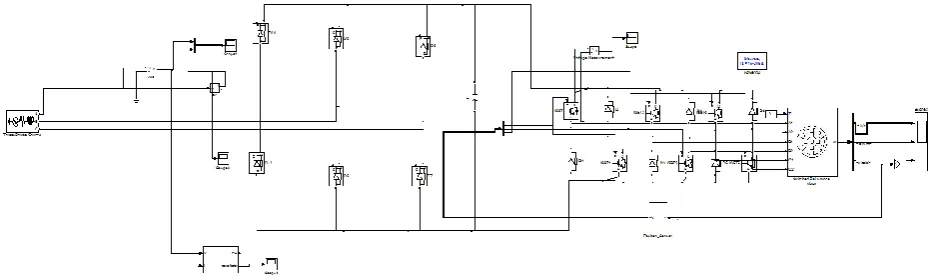
Fig 5: Simulation Diagram for Proposed Converter
A current source rectifier (CSR) based converter is established to modify the input current of the drive,
improving the power factor of SRM drive. Dc link's capacitors eliminating and as a result creating capability of
energy saving in regenerative operation mode of SRM is achieved by CSR based converter. The input phase
current frequency spectra clearly illustrate current THD improvement through power factor correcting. As an
application, front-end large filter capacitor can be used to battery charging in regenerative mode of switched
reluctance motor. The switching topology and control algorithm is implemented on DSP-equipped SRM. The
simulation and experimental results demonstrate the desired condition.
REFERENCES
[1] R. Krishnan, Switched Reluctance Motor Drives, Boca Raton, FL: CRC Press, 2001.
[2] M. Cacciato, A. Consoli, G. Scarcella and G. Scelba, “A switched reluctance motor drive for home
appliances with high power factor capability,” in Power Electronics Specialists Conference - PESC 2008,
Jun 15-19, 2008, pp. 1235 – 1241.
[3] W. K. Thong and C. Pollock, “Low-Cost Battery-Powered Switched Reluctance Drives with Integral
Battery-Charging Capability,” IEEE Trans. Industry Applications, Vol. 36, No. 6, pp 1676-1681,
Nov./Dec. 2000.
[4] S. Narla, Y. Sozer, and I. Husain, “Switched Reluctance Generator Controls for Optimal Power
Generation and Battery Charging” IEEE Trans. Industry Applications, vol. 48, no. 5, pp 1452-1459,
Sep./Oct. 2012.
[5] P. Zhang, P. A. Cassani, and S. S. Williamson, “An Accurate Inductance Profile Measurement Technique
for Switched Reluctance Machines,” IEEE Trans. Industrial Electronics, vol. 57, no. 9, pp 2972- 2979,
Sep. 2010.
[6] R. Krisinan, G. H. Rim, Modeling, “Simulation An Analysis Of Variable Speed Constant Frequency
Power Conversion Scheme with A Permanent Magnet Brushless DC Generator,” in Proc. 1988 IEEE
Industrial Electronics Society Conf IECON, pp. 332 – 337.
[7] L. Huber and D. Borojevic, “Space Vector Modulated Three-Phase to Three-Phase Matrix Converter with
Input Power Factor Correction,” IEEE Trans. Industry Applications, vol. 31, no. 6, pp. 1234-1246,
Nov/Dec. 1995.
[8] H.R. Karshenas, J. Mousavi, “A new direct sinusoidal input/output acac converter with unidirectional