Effect of CFRP for Strengthening the Beam
Column Joint under Torsion
Anil Varghese, Dr. Sheela S
Assistant Engineer, Greater Cochin Development Authority, Ernakulam, Kerala, India
Principal, Mohandas College of Engineering and Technology, Thiruvananthapuram, Kerala, India
ABSTRACT: Generally stress resultants such as axial forces, shear forces, bending moments, torsion or a combination of these effects may occur in RC members of a structure. Bending moments and shear forces are the primary criteria for most design situations and torsion is either neglected or under estimated. Also the RC structures may not be designed to resist the torsion created due to loading eccentricities or additionally created torsion due to earthquakes, accidently caused unbalanced loading etc. Hence many of the existing structures are deficient in terms of torsion and needs strengthening. An experimental study has been conducted to study the behaviour of RCC beam column joint specimen strengthened with CFRP under torsion. From the study it was observed that CFRP is effective for strengthening the beam column joint against torsion.
KEYWORDS: Strengthening, CFRP, Torsion
I. INTRODUCTION
Most of the structures we see are invariably made of the most popular construction material, Reinforced Cement Concrete or RCC. Even though RCC is a wonderful construction material, it is very difficult to increase its strength once it set. Another major drawback with RCC is that at most places it is largely manufactured by unskilled workers, and if seemingly minor but important points, if not kept in mind leads to RCC of reduced strength. Some of these issues are due to increase in water cement ratio, improper curing etc. For a number of reasons, such as substandard detailing of the steel reinforcement, deterioration of the concrete under severe environmental conditions or improper construction, strengthening the reinforced concrete become necessary.
Due to torsion reinforced concrete members will be subjected to diagonal tension and compression and fails in a brittle manner. Brittle failure of elements is undesirable as it could lead to an inductile behaviour of structures during earthquakes. Strengthening and rehabilitation of structures has been an important research topic worldwide during the past decade. Strengthening of concrete structures could be an optimum solution in many cases such as change in the usage of the building or change in the design codal provisions [1].
This paper discusses the experimental study conducted on RCC beam column joint specimen retrofitted with CFRP under torsion.
II. PRELIMINARYINVESTIGATIONS
A preliminary investigation was carried out to determine the properties of the constituent materials for the preparation of M20 grade concrete and thus arriving the optimum proportion for the M20 concrete.
A. PROPERTIES OF CONSTITUENT MATERIALS
Properties of the constituent materials used for the study are as follows.
1. Cement
2. Sand
Locally available good quality river sand was used. Sand belongs to zone I as per IS 383-1970. The optimum moisture content was 6% percentage with a maximum bulking of 37.82% and Fineness modulus of sand was 3.41.The properties of sand conform to IS 383-1970 [3].
3. Coarse aggregate
Crushed aggregate with a maximum size of 20mm was used. The fineness modulus of aggregate was 7.08 and thespecific gravity was 2.86 [4]. The properties of coarse aggregate conform to IS specifications.
4. Steel
High yield strength deformable bars of 6mm and 8mm diameter were used. The properties of steel bars are shown in Table I.
TABLE I. PROPERTIESOFSTEELRODS
Particulars 6mm bars 8mm bars
Yield Stress ( N/mm2) 468.39 440.85
Ultimate Stress ( N/mm2) 555.13 608.91
Modulus of Elasticity (N/mm2) 2.0 x 10⁵ 2.1 x 10⁵
5. Carbon Fibre Reinforced Polymer (CFRP)
The carbon fibre used was Nitowrap EP (CF). Nitowrap EP (CF) is a carbon fibre composite wrapping system where it is used in conjunction with an epoxy sealer cum primer (Nitowrap 30) and a high build epoxy saturant (Nitowrap 410). The properties of CFRP, which is given by Fosroc Chemicals Ltd., are given in Table II
TABLE II. PROPERTIESOFCFRP
Particulars Properties
Fibre Orientation Unidirectional
Weight of Fibre 200 g/m2
Density of Fibre 1.80 g/cc
Fibre Thickness 0.30 mm
Ultimate elongation 1.5 %
Tensile Strength 3,500 N/mm2
B. MIX DESIGN
M20 concrete mix was prepared as per IS 10262-1982 [5] recommendations. The design mix proportion obtained as
per code was 1: 1.617: 3.40: 0.5.By varying the cementcontent trial mixes were prepared to determine the suitable mix proportion, with optimum cement content, satisfying the workability criteria. The details of trial mixes were tabulated in Table III.
TABLE III. DETAILSOFTRIALMIXES
Trial Mix Cement Content (kg/m3) Slump (mm) Compact ing Factor Compressive strength (N/mm2) 7th day 28th day
Mix 1 370 16 0.89 26.20 36.31
Even though Mix 5 satisfies the strength criteria, the mix was found as so stiff and not workable. Hence from the trial mixes, Mix 4 with cement content 355 kg/m3 was chosen for the further study which satisfies the required workability and strength. Optimum mix proportion for M20 concrete was found out as 1: 1.708: 3.591: 0.50.
III.EXPERIMENTALINVESTIGATIONONBEAM-COLUMNJOINTS
Three sets of beam column joint specimens having three numbers of specimens were prepared. The size of beam for the beam column joint specimen was selected as 100 x 150 mm having 600 mm length and the column portion was 100 x 150 mm with 1000 mm length. The sizes of the specimens were arrived based on the literature [6] and the fabrication and testing facilities available in the laboratory. Out of the three sets one set of beam column joints was the control specimen and two other sets were the specimen strengthened with CFRP. The designation of the beam column joint specimen is given in Table IV.
TABLE IV. DESIGNATIONOFBEAMCOLUMNSPECIMEN
Beam Designation Description
BCJ Control Specimen
BCJ CF-01 Specimen strengthened with one layer of CFRP
BCJ CF-02 Specimen strengthened with two layer of CFRP
A. REINFORCEMENT DETAILS OF BEAM-COLUMN JOINT
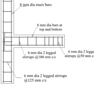
Minimum reinforcement as per IS 456:2000 [7] was provided for the beam column joint specimen. The details of reinforcement of the specimens are given in Fig. 1.
Fig. 1. Reinforcement detailing of beam column joint
B. PREPARATION OF RETROFITTED SPECIMENS
Fig. 2. Strengthening Scheme
CFRP was applied in one and two layers. CFRP sheets were fixed to the concrete surface by using an epoxy sealer cum primer (Nitowrap 30) and a high build epoxy saturant (Nitowrap 410).
C. EXPERIMENTAL SET UP
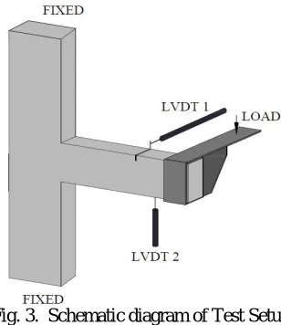
All the beam column joint specimens were tested in a loading frame. The column portions of the specimen were fixed at the ends and beam end was free. An eccentric load was applied at the beam end to produce torsion. Fig. 3 shows the schematic diagram of introducing torsion in the specimen.
Two LVDT’s were used to measure the deformations. One LVDT was placed horizontally to measure the beam rotation and the other was placed vertically to measure the deflection at the beam end. Loading was applied by using a hydraulic jack and a load cell of capacity 50 T was used to measure the load.
Fig. 3. Schematic diagram of Test Setup
Fig. 4.Test setup with beam column joint
Observations like first crack load, ultimate load, load vs. deflection, crack formation and pattern were taken and tabulated.
D. RESULTS AND DISCUSSIONS
The discussion on the results of specimens tested under static loading is shown under different heads.
1. First Crack Load and Ultimate Torque
The first cracking load and ultimate torque of the different beam-column specimen is given in the Table V.
TABLE V. FIRSTCRACKLOADANDULTIMATETORQUEOFSPECIMEN
Specimen Designation
First Crack Load Ultimate Torque
kN % increase kN % increase
BCJ 6 -- 3.6 --
BCJ CF-01 8 33.33 4.5 25.00
BCJ CF-02 9 50.00 4.8 33.33
It is clear that the first crack load of the beam column joint specimen increase due to strengthening. The first crack load and ultimate torsional capacity of the specimen retrofitted with two layers of CFRP was increased by 50% and 33.33% respectively as compared with the control specimen.
2. Load Deflection Characteristics
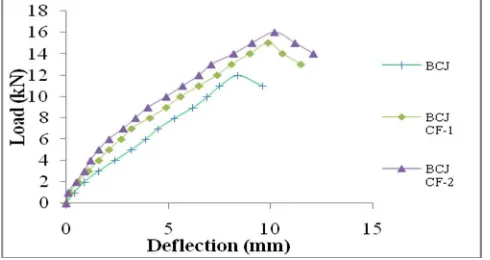
The deflections at free end of the beams were plotted against the loads at an interval of 1 kN. The load-deflection behaviour for each category of beam column joint was compared and is given in Fig.5.
It may be observed that, for a particular load, the deflection of all the strengthened beam-column joints were found to be lesser than that of the control specimen in the pre-cracking stage but a greater deflection at ultimate load was observed when compared to that of the control specimen.
3. Torque Twist Characteristics
The angle of twist at the beam was plotted against the torque at an interval of 1 kN-m. The torque twist behaviour for each category of specimens were compared and given in Fig.6.
Fig. 6. Torque Twist Characteristics of Specimen
A similar trend as the load deflection was obtained for the torque twist behaviour. From the Fig.6 it may be observed that, for a particular torque, the twist of the strengthened beam-column joints were found to be lesser than that of the control specimen in the pre-cracking stage but a greater twist at ultimate torque was observed when compared to that of the control specimen. The specimen BCJ CF-2 showed superior behaviour as compared with all other specimens.
4. Energy Absorption Capacity
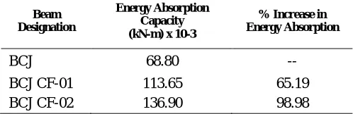
Energy absorption capacity of the structural member plays an important role in the behaviour of structures against earthquake. Energy absorption capacity of a member is derived from the deflection curve. The area under the load-deflection curve gives the energy absorption capacity, for all the specimens and it is tabulated in Table VI.
TABLE VI. ENERGYABSORPTIONCAPACITYOFSPECIMENS
Beam Designation
Energy Absorption Capacity (kN-m) x 10-3
% Increase in Energy Absorption
BCJ 68.80 --
BCJ CF-01 113.65 65.19 BCJ CF-02 136.90 98.98
5. Deflection Ductility Ratio
TABLE VII. DEFLECTIONDUCTILITYRATIO
Specimen Designation
Deflection (mm) at
Deflection Ductility Ratio Increase in Ductility Ratio (%) Yield Load Ultimate Load
BCJ 4.0 8.4 2.10 --
BCJ CF-01 4.1 9.9 2.41 14.76
BCJ CF-02 4.0 10.20 2.55 21.42
After strengthening, the specimens showed large deflection at ultimate load, thus there was a significant increase in the ductility ratio. The specimens strengthened with two layers of CFRP showed the maximum increase of 21.42% in deflection ductility ratio as compared with control specimen.
6. Torsional Ductility Index
Torsional ductility of a member refers to the capacity of the member to yield without breaking. It is the ratio of the angle of twist at ultimate torque to that at yielding torque. The ductility ratio for each specimen category was calculated and is given in Table VIII.
TABLE VIII. TORSIONALDUCTILITYINDEX
Specimen Designation
Angle of Twist
(rad/m) at Torsional
Ductility Index Increase in Ductility Index (%) Yield Torque Ultimate Torque
BCJ 0.166 0.375 2.26 --
BCJ CF-01 0.156 0.389 2.49 10.17
BCJ CF-02 0.153 0.359 2.35 3.98
From the Table VIII it can be observed that strengthened specimens showed large twist at the ultimate load, thus there was an increase in the torsional ductility ratio. The specimen BCJ CF-1 showed the highest torsional ductility index of 2.49 with an increase of 10.17%.
7. Crack Pattern
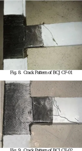
Fig. 8. Crack Pattern of BCJ CF-01
Fig. 9. Crack Pattern of BCJ CF-02
The failure of the strengthened specimen was partially delayed in respect to the failure of the control specimens, but eventually diagonal torsional cracks occurred and widened in the unwrapped concrete part. From Fig 8and Fig. 9 it may be observed that, failure of strengthened specimens were characterized by the formation of inclined cracks beyond the strengthened portion of the beam without any crack at the joint. Hence strengthening enhances the torsional behaviour of beam column joint and also it satisfies the strong column weak beam concept. Control specimens failed due to the advancement of crack width at beam-column interface.
8. Cost Assessment
A detailed cost analysis to check the economic feasibility of different strengthening techniques was conducted. The economic feasibility of the different strengthening techniques can be evaluated by the cost to strength ratio. The cost to strength ratio for different retrofitted specimens is compared with the control specimen. In this case the increase in ultimate torsion is considered for the strength ratio. The comparison is given in Table X.
TABLE X
COST TO STRENGTH RATIO OF SPECIMENS
Specimen Cost
(Rs.)
Cost Ratio
Strength (kN-m)
Strength Ratio
Cost/ Strength
Ratio
It is noted that beam column joint specimens retrofitted with one layers of CFRP fabric are the most efficient as its cost to strength ratio is the lowest at 1.82 as compared to the other strengthening techniques.
IV. CONCLUSIONS
The following conclusions were arrived at based on the experimental investigation conducted.
Strengthening techniques can be adopted as a feasible solution for enhancing the torsional capacity of concrete members
Confinement wasachieved by wrapping the specimen with the ferrocement and the torsional and flexural behaviour were enhanced due the confinement pressure exerted by the strengthening material.
The cracking behaviour of the specimens was enhanced due the presence of fabrics which delayed the crack initiation and inhibited the propagation of crack because of its high tensile capacity.
First crack load and Ultimate torsional capacity were increased by 50% and 33.33% respectively for the specimen retrofitted with two layers of CFRP.
Strengthened specimens showed large deflection at the ultimate load, thus there was a significant increase in the ductility ratio. The specimen BCJ CF-2 showed the highest deflection ductility ratio of 2.55 with an increase of 21.42% as compared with the control specimen.
All strengthened specimens showed considerable increase in the energy absorption capacity. The specimen BCJ CF-02 recorded the maximum energy absorption capacity which was increased by 98.98 % than the control specimen.
Control specimens failed due to the advancement of crack width at beam-column interface whereas no cracks were observed at beam column interface for strengthened specimens.
Failure of strengthened specimens were characterized by the formation of torsional cracks occurred beyond the strengthened portion of the beam.
Beam column joints strengthened using one layers of CFRP were the most cost effective with a minimum cost to strength ratio of 1.82.
Considering all the results obtained from the experiment, beam column joints strengthened using two layers of CFRP were found out as the most efficient for strengthening.
REFERENCES
[1] Deifalla A and Ghobarah A,(2010), “Full Torsional Behaviour of RC Beams Wrapped with FRP: Analytical Model”, Journal Of Composites For Construction, Vol.14, pp. 289-300
[2] IS: 12269-1987, “Specification for 53 grade Ordinary Portland Cement Indian Standard Code on properties of Cement”, Bureau of Indian Standards, New Delhi.
[3] IS 383-1970, “Specification for coarse and fine aggregate from natural sources for concrete” Bureau of Indian Standards, New Delhi. [4] IS 2386 Part III -1963, “Indian standard code on methods for test of coarse aggregate”. Bureau of Indian Standards, New Delhi. [5] IS: 10262-1982, “Recommended guidelines for Concrete Mix Design”, Bureau of Indian Standards, New Delhi.
[6] Amal K Sajeev, Sheela S, (2010), “Studies on the Performance of Rubberized RC beam-column joints strengthened using Concrete Jacketing Technique”,Thesis, Department of Civil Engineering, College of Engineering Trivandrum