International Journal of Innovative Technology and Exploring Engineering (IJITEE) ISSN: 2278-3075, Volume-8 Issue-9, July 2019
Strengthening of Fired RC Beam Column Joint
using Geosynthetics
Liju T Abrahm, Narasimha Murthy K N
Abstract: From the past few decades, there has been a steady growth in the field of construction of building all over the globe. With the technological advances on all fronts the complexity of fires, explosions and the hazards are major challenge thrown up to the planner, engineer and architects. Hence, new techniques and sustainability material have to be adapted for the retrofitting of fire damaged buildings. Notable work has been done with Glass Fibre Reinforced Polymers (GFRP), Carbon Fibre Reinforced Polymers (CFRP) and Basalt Fibre Reinforced Polymer (BFRP) as a fibre reinforced polymers used as a
retrofitting material. But less work has been done with geosynthetics material (Gotextiles. Geogrids, Geonets, Geomembranes) . The main purpose of this research study is to evaluate the behaviour of fired RC beam-column joint specimens wrapped with Geogrid and Glass Geocomposite. In the process, 12 beam-column joint specimens were casted out which 9 were fired at a temperature of 6000c for 6 hours and 6 specimens were wrapped with the geosynthetics (3- wrapped with Geogrid, and 3- wrapped with glass fibre) and remaining 3 specimens were tested directly without any wrappings. Studies were performed on the control specimens and the wrapped/ retrofitted specimens for engineering properties. From the result, it has been observed that geogrid wrapped fired specimen and glass geocomposite wrapped fire specimen showed more deflection than control specimen and had higher load carrying capacity than the fired specimen without wrapping.
Keywords: Beam-Column Joint, Geogrid, Glass Geocomposite, wrapping, Fired Specimen.
I. INTRODUCTION
Reinforced concrete structural system are quite frequently used in high rise building due to a number of infrastructure advantage they provide over other material .Concrete as a structural material performs well under fire conditions due to its incombustibility and low thermal conductivity. In a reinforced concrete structure, which was detailed as per the provisions, will transfer the loads from damaged sections to the concrete components which were not damaged when subjected to fire. Therefore, it's not common for fire-damaged RC structures to utterly collapse during or after an event of fire [1] .Beam-column joints are majorly designed for maximum load carrying capacity strength to resist horizontal and vertical forces. Most of research of has been done for force which arising due to seismic excitation in beam column joint but very less research done on fire performance of RC beam column joint. Over the year, several fire accidents broke out in various part of India. When fire accident occurred in a building,
..
Revised Manuscript Received on July 05, 2019
Liju T Abrahm, Dept. of Civil Engineering, Faculty of Engineering, CHRIST( Deemed to be University), Bengaluru, India.
Narasimha Murthy K N, Dept. of Civil Engineering, Faculty of Engineerring, CHRIST( Deemed to be University), Bengaluru, India.
column and beam strength got deteriorated and crack will occur. So to demolition and replacing the structure will be expensive so retrofitting of structure will be cost effective and less time consuming [2]. In this paper we are using static loading condition so primary concern will be strength parameter secondary concern will be ductility [3].
The beam-column joint is a critical section in a framed structure where compression and tension force act from beam ends and axial load from column ends are transferred directly to the joint. The principal objectives for failure of a beam-column joint are to avoid shear failure and tensile stresses which causes the diagonal cracks at the joint .This condition occur when reinforcement bar that are in top that are pulled in one direction and other are pulled in other direction in the joint area which cause immediate deterioration and crushing of concrete [4].There are 3 type of joint in moment resisting frame i.e. interior joint, exterior joint, corner joint. It has also been found that exterior beam column joints are more vulnerable than interior joints [5]. It has seen that beams were subjected to fire flamehave two types of cracks developed. The first was thermal cracks, which appeared in honey comb fashion all over the surface. The second cracks originated at mid-span region due to bending from the applied load and called flexural crack [6].It was seen that at 6000c there was reduction 50% from the original strength of cube [7].
Evaluation for fire damaged building has been based upon understanding of visual assessment, non-destructive and destructive tests, condition survey ,duration and temperature of fire .Apart from this, retrofitting techniques where selected on basis of efficiency, economy, and performance. The quite commonly practiced techniques used are replacement of damaged concrete either with shotcrete or in-situ placement of concrete and fibre reinforced polymer. Some modern techniques which are also used now days are steel jacketing, concrete jacketing but every technique will have its own pro’s and con’s like in steel jacking, steel plate will get corrugated and required intense labour .FRP wrapping technique exhibit high strength, easy application , corrosion resistance and can covers almost all geometries of buildings .
II. LITERATURE REVIEW
The experiment investigation was conducted on the strengthening of the exterior beam-column joint using natural and basalt fibre.so six exterior beam-column joint were cast with dimension are as follow (Beam cross section are 100X100mm with length 750mm and column cross section are 100X100 with height 1000mm) designed as per IS: 456:2000. Static loading
was applied on two control
beam column joint
ultimate failure load and remaining four specimens were tested up to seventy percent of its ultimate load of control specimen .so that later specimen can be retrofitted with the monolithic and hybrid wrapping of fibre. Wrapping has been done by epoxy resin (Araldite GY 257) and hardener (Hardener HY 840) .where for monolithic wrapping, basalt fibre has been used while for hybrid wrapping, glass and basalt has been used. After testing the following parameter has been discussed and a comparative study has been done with control and retrofitted specimen. According to result, it was seen that structure rehabilitated with the hybrid wrapping of basalt fibre reinforced polymer and glass fibre reinforced polymer showed an increase in energy absorption, ductility, initial and ultimate load capacity than control specimen [8].
The experimental investigation was conducted on reinforcement concrete beams with uniaxial and biaxial geogrids. Geogrid is used in concrete pavements which provide soil stabilization. In this study total, 8 geogrid concrete beams and 2 control beams were cast and tested under two-point load bending. The main objective of this project is to find out flexural behaviour of plain concrete beam compared to reinforce with uniaxial and biaxial geogrid with a different layer. In this experiment, the steel bar placed in concrete. The beam of cross section 100 X 150 mm and a span length of 1200mm with the different layer of geogrid was used. A comparative study has been done between uniaxial, biaxial and control beam showing maximum flexural strength and displacement curve for beam were calculated. Crack pattern was observed on the middle portion for geogrid beam only flexural crack has appeared no shear cracks has formed but for control beams both cracks have appeared .it was concluded that flexural strength and load-deformation behaviour of beam depends upon no of layer of geogrid placed hence takes tensile force and can be used as steel structural member [9].
The strengthening of RC structures using textile
reinforcement. Initially, beams of size
1500mmX150mmX250mm were cast, further, it was tested by applying a load of 50kN. The failed specimen was retrofitted using basalt textile mesh. It was noted the retrofitted beams had a ductile failure compared to the brittle failure of the conventional beam. The beams with basalt textile mesh had a flexural strength of more than 30 % compared to that of control specimens. The study concluded that the retrofitted has less deflection rate than the deformation level of the control specimens [10].
III. EXPERIMENTAL INVESTIGATION A. Properties of Material used:
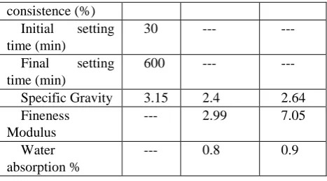
Cement: 53 grade confirm to the IS 12269-1987
[image:2.595.310.544.49.178.2]Fine Aggregate M-sand and Coarse Aggregate 20 mm was confirm as per requirement of IS 383:1970. and shown in Table 1.
Table 1: Physical Properties of Materials Material/Propert
ies
Cem ent
Fine Aggregates
Cours e Aggrega tes
Standard 32 --- ---
consistence (%) Initial setting time (min)
30 --- ---
Final setting time (min)
600 --- ---
Specific Gravity 3.15 2.4 2.64
Fineness Modulus
--- 2.99 7.05
Water absorption %
--- 0.8 0.9
B. Details of specimen:
The details of the specimens as below and beam column joint specimens designed as per IS 456:2000. Beam Cross section = 150 mm × 200 mm with Cantilever length = 600 mm.Top reinforcements = Two bars of 12 mm diameters. Bottom reinforcements = Two bars of 12 mm diameter. Stirrups = 8 mm diameter with the spacing of 150 mm centre to centre (c/c). Column Cross section = 200 mm × 150 mm with Height = 800 mm. Main reinforcement = Four bars of 12 mm diameter. Vertical ties = 8 mm diameter with a spacing of 150 mm centre to centre (c/c).
C. Casting and Curing of the specimens:
The specimens were casted for the design mix of M20 grade concrete with slump value 100mm. A motor operated Needle vibrator was used for compacting the concrete., then the specimens were kept undistributed for 24 hours as shown in Figure 1. After 24 hour, formwork will be taken out from specimen and wet jute bag was covered over specimen and water curing was done for next 28 days as shown in Figure 1.
Figure 1: (a ) Casted specimens , (b) Curing of specimens
D. Firing of Specimens:
As per requirement of the research study, the beam column joint specimens were fired to a temperature of about 600o c. It was found by several research studies that any concrete specimens which were subjected to a temperature of more than 800c will be remained useless and when the temperature is of about 600c there will be formation of cracks and such specimens can be used after certain retrofitting procedures. Hence the temperature in this research study was finalized
[image:2.595.313.548.465.628.2]International Journal of Innovative Technology and Exploring Engineering (IJITEE) ISSN: 2278-3075, Volume-8 Issue-9, July 2019
As process of maintaining the temperature of about 6000 c, a chamber of dimensions 200x100x 80cm as showed in Figure 2 was built out of bricks with 3 outlets at different locations to record the temperatures. The coal is used as a fuel to maintain the desired temperature. Thermocouple was used to record the temperature at the regular intervals of time at different outlets as mentioned above. This whole firing process has been carried out for 15 hours to ensure the uniform distribution of the temperature in the chamber. After 24 hours the chamber was kept open and the whole setup was allowed to cool down. The variation of temperature with time is shown in Figure 3.
Figure 2: (a) Setup for firing of specimens (b) Recording temperature using Thermocouple
Figure 3: Time Vs Temperature Variation E. Fibre used for wrapping of specimen:
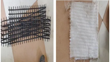
Geogrids are made from polymeric coated polyester material which has high tenacity, molecular weight and low carboxyl end group polyester yarns. It is knitted to form grid like structures.
Glass Geo-composite are made from the high performance glass fibre used with non-woven polymer material where glass fibre is roping to form net like structural material. The physical structure of the fibres are as shown in Figure 4.
Figure 4: (a) Geogrid fibre (b) Glass geocomposite F. Testing of specimen:
Test was done on exterior beam column joint on 200T capacity loading frame. The static load was apply on 12 beam column joint specimens out of which (3 were control specimens, fired specimens and retrofitted specimens) the axial constant load of 200kN was applied on column so that both end of column are fixed which is about 20% from total capacity of column. Load was continuously applied until the specimen fails, and the load at which the specimen failed was termed as ultimate load. Results obtained after testing are Initial and Ultimate Cracking Load, Load Displacement Curve, Energy Absorption
G. Bonding procedure :
[image:3.595.55.288.197.325.2]Before wrapping of the fired specimens, the surface is cleaned to remove the loose materials present on it, so that it won’t affect the wrapping process. Epoxy resin mixed with hardener with a ratio of 1:0.5 and the resin was applied in layers over the specimens. The applied resins were allowed to set along with wrappings for about 24 hours without being disturbed. It was observed that duration of 7 days was taken by the resin to get completely polymerized. The specifications of epoxy resin and hardener is shown in Table 2 and Table 3.
Table 2: Specification of epoxy Resin
Property Test
Method
Unit Value
s Epoxy Group
Content
SMS 2026
Mmol/kg
5260-5420
Viscosity At 25֯c ASTM
D445
10 poise 12-14
Colour ASTM
D1209
Pt-co 100
max
Density SMS
1347
[image:3.595.58.290.357.520.2]Kg/L 1.16
Table 3: Specification of hardener
Product name Hardener 620
Appearance Colourless clear
viscous liquid
Specific gravity 1.01-1.04
Viscosity 02-May
IV. RESULT AND DISCUSSION
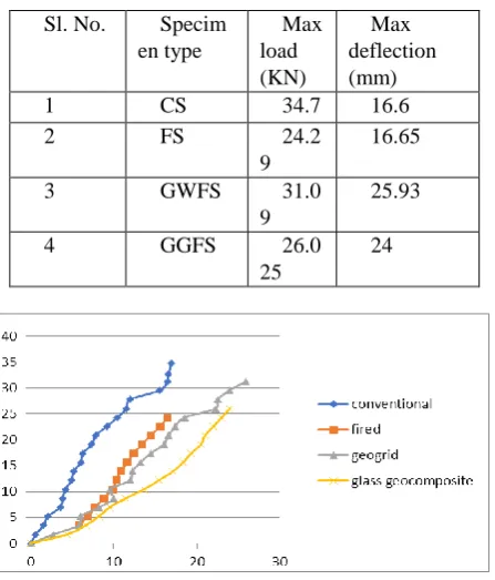
[image:3.595.57.282.641.767.2]The specimen were tested using loading frame by gradually increasing the load until its failure. The results were tabulated in Table 4. It is observed that the deflections were maximum in geogrid wrapped fired specimen followed by glass geocomposite fired specimens and control specimens showed maximum load carrying capacity. The fired specimens showed decrement in load carrying capacity but after wrapping with geogrid and glass geocomposite on fired specimen showed an increment in load carrying capacity as well as increase in deflection and the same is shown in Figure 5.
Table 4: Failure load and Deflection Values
Sl. No. Specim
en type
Max load (KN)
Max deflection (mm)
1 CS 34.7 16.6
2 FS 24.2
9
16.65
3 GWFS 31.0
9
25.93
4 GGFS 26.0
25
24
Figure 5 : Failure load vs. deflection curve CS-Controlled Specimens
FS- Fired Specimens
GWFS-Geogrid wrapped fired specimens GGFS-Glass Geocomposite Fired Specimens
B. Initial and ultimate cracking load
The initial cracking and ultimate loads of conventional specimens was higher than retrofitted specimen followed by fired specimen. It was seen that retrofitted specimen with geogrid and glass Geocomposite took more load than fired specimen because stress where taken by fibre wrapped around specimen by using epoxy resin. The values initial and ultimate cracking loads are shown in Table 5 and Figure 6.
Table 5: Initial and ultimate cracking loads
Specim en
Initial cracking load (kN)
Ultimate cracking load (kN)
CS 26.6 34.7
FS 15.55 24.29
GWFS 22.55 31.23
[image:4.595.58.282.215.477.2]GGFS 19.085 26.05
Figure 6 : Initial and ultimate cracking loads. C. Deflection ductility ratio and Stiffness
[image:4.595.309.544.329.410.2]Deflection ductility is the ratio ofdeformation at ultimate load to yield load and stiffness ultimate load to maximum deformation. Table 6 shows that geogrid wrapped specimens showed ultimate deflection value while control showed higher stiffness value.
Table 6: Deflection ductility Ratio and stiffness Specimen
Type
Deflection ductility ratio
Stiffness (kN/mm)
CS 1.17 2.09
FS 1.00 1.45
GWFS 1.27 1.19
GGWFS 1.25 1.08
In this research a comparative study has been made between control specimens, fired specimens, geogrid wrapped fired specimens and glass geocomposite wrapped fired specimens for initial cracking load, ultimate load, deflection ductility and stiffness at ultimate loads.
Cracking Load and Ultimate loads:
[image:4.595.305.553.564.832.2]From the Table 7 it has been observed that fired specimens have 41.7% decreases in first cracking load than control specimen. Geogrid wrapped fired specimens showed increment of 31% than fired specimens and decrement of 15.2% than control specimens.
Table 7: Variations of Cracking load and Ultimate loads
Speci men Type
Load Point
L oad (kN)
% Variation for CS
% Variations for GWFS
% Variations for GGWFS
CS Crack
ing point 26 .60
- +15.2 39.3
Ultim ate point
34 .70
- +11.1 33.20
FS Crack
ing point 15 .55
-41.7 -31.0 -18.52
Ultim ate point
24 .29
-30 -22.22 -6.75
GWF S
Crack ing point
22 .55
-15.2 - 18.15
Ultim ate point
31 .23
-10 - 19.88
GGW FS
Crack ing point
19 .08
-28.25 -15.36 -
Ultim ate point
26 .05
International Journal of Innovative Technology and Exploring Engineering (IJITEE) ISSN: 2278-3075, Volume-8 Issue-9, July 2019
It is also been observed that control specimens had an ultimate load carrying capacity, 30% increases in ultimate load carrying capacity than fired specimen. While geogrid specimen has 22.2 % increases in ultimate load carrying capacity than fired specimen.
Deflection Ductility and Stiffness:
It was observed from Table 7 that geogrid and glass geocomposite has higher deflection ductility than control and fired specimens. Which indicate that fired specimens are more brittle. Geogrid specimens are having increment of 21.2% in deflection ductility than fired specimens. While, glass geocomposite specimens having increment of 6.83% than control specimens.
Table7: Deflection Ductility and Stiffness values D eta ils of Sp eci me n
Description %
Variat ion for CS % Variati ons for GWFS % Vari atio ns for GG WF S C S Deflecti on/Ductilit y 1. 17 - -7.87 -6.40 0 Stiffness 2.
09
- +75.
6 9 3.51 F S Deflecti on/Ductilit y 1. 00 -14.50 -21.20 2 0.00
Stiffness 1. 45 -30.6 +21. 8 3 4.25 G W FS Deflecti on/Ductilit y 1. 27 +8. 50
- 1.
60
Stiffness 1. 19
-43.06
- 1
0.18 5 G G W FS Deflecti on/Ductilit y 1. 25 +6. 83 -1.57
Stiffness 1. 08 -48.32 -9.24 -
The control specimens showed higher stiffness among other specimens. Control specimen showed 75 % increment in stiffness and fried specimen showed 21.8 % increment in stiffness compared to geogrid fried wrapped specimen.
V. CONCLUSIONS
Following conclusion were arrived based on experimental investigations.
CS showed maximum load carrying capacity among other specimens.
The first cracking load is increased by 31% for GWFS and 18.6 % for GGWFS compared to FS.
The ultimate load is increased by 23% for GWFS and 7 % for GGWFS compared to FS.
Load deflection at a particular load, GGWFS and GWFS showed higher deflection than FS and CS showed least deflection among other specimens.
The deflection ductility ratio is increased by 21.2% for GWFS and 20% for GGWFS when compared with FS, it shows that FS are more brittle.
The stiffness is decreased by 75.6% for GWFS and 93.5 % for GGWFS compared to CS.
REFERENCES
1. Ha, T., Ko, J., Lee, S., Kim, S., Jung, J. and Kim, D.J., 2016. A Case Study on the Rehabilitation of a Fire-Damaged Structure. Applied Sciences, 6(5), p.126.
2. Awoyera, P. O., Akinwumi, I. I., Ede, A. N., & Olofinnade, O. M. (2014). Forensic investigation of fire-affected reinforced concrete buildings. IOSR Journal of Mechanical and Civil Engineering (IOSR-JMCE), 11(4), 17-23.
3. Patil, S. S., and S. S. Manekari. "A Study Of Rcc Beam-Column Connection Subjected To Monotonic Loading."
4. Ganesh B. Kawale, Dr. G.R. Selokar, Dr. Ashok L.Varne,Prof. R. S. Narkhed(2017). “Strengthening of Beam-Column Joints in RC Frames Using Steel Sections” international research journal of engineering and technology (volume 4:issue6)
5. El-Amoury, T., and A. Ghobarah. "Seismic rehabilitation of beam– column joint using GFRP Sheets." Engineering Structures 24.11 (2002): 1397-1407.
6. Kadhum, Mohammed Mansour, Nada Mahdi Fawzi, and Khalid Safa'A. Hashim. "Experimental Studies on The Fire Endurance of Reinforced Concrete Beams." University of Babylon Repository (2003).
7. Elizzi, M. A. S., Al-Maddad, A. M. H., Yousif, S. H., & Ali, A. K. (1987). Influence of Different Temperature on Compressive Strength and Density of Concrete. Journal of Building Research Vol., November, 1-3.].
8. Gnanapragasam, A. Arul, G. Chitra, and S. Robert Ravi. "Study on Strengthening of RC Beam Column Joint Using Hybrid FRP Composites." Scientific Research publishing 7 (2016): 2846-56. 9. Shobana, S., and G. Yalamesh. "Experimental study of concrete
beams reinforced with uniaxial and biaxial geogrids." International Journal of ChemTech Research CODEN (USA): IJCRGG, ISSN (2015): 0974-4290.
10. P.B Jayakrishnan and,Paul Shaji (2018). “A Study on the Strengthening of RC Beams Using Textile Reinforcement” International Research Journal of Engineering and Technology (volume 5: issue 4).
11. Standard, Indian. "IS-456. 2000." Plain and Reinforced Concrete-Code of Practice”, Bureau of Indian Standards, Manak Bhawan 9 (2000).
12. Shetty, M. S. "Concrete technology." S. chand & company LTD(2005): 420-453.
13. Park, R., & Paulay, T. (1975). Reinforced concrete structures. John Wiley & Sons.
AUTHORS PROFILE
Liju T Abraham has obtained B.Tech in Civil Engineering and perusing M.Tech in Structural Engineering at
CHRIST(Deemed to be
Narasimha Murthy K N has obtained B.E degree in civil Engineering, M.Tech (Industrial Structures) and Ph.D in Image processing. Currently he is working as a Professor in the
Department of Civil
Engineering. His areas of interests are Structural Health
Monitoring, Reuse of