ISSN(Online): 2319-8753 ISSN (Print): 2347-6710
I
nternational
J
ournal of
I
nnovative
R
esearch in
S
cience,
E
ngineering and
T
echnology
(A High Impact Factor, Monthly, Peer Reviewed Journal)
Visit: www.ijirset.com
Vol. 8, Issue 6, June 2019
Implementation and Applications of
CORDIC Algorithm in Satellite
Communication
Mr Manoj S Jadhav, Dr.Manik S Gaikwad
Dept. of E&TC, Sinhgad Institute of Technology, Lonavala, India
Principal, Sinhgad Institute of Technology, Lonavala, India
ABSTRACT: CORDIC stands for COrdinate Rotation DIgital Computer, is a algorithm, based digital signal processing has become an important tool in communications biomedical and industrial products, providing designers with significant impetus for making algorithm into architecture. In this paper, a new kind of CORDIC algorithm was presented which was based on the state machine structure and iterative operation of multilevel pipeline architecture. The algorithm has been realized in the FPGA using the multilevel pipeline architecture. At the end, by the simulation waveform and spectrum analysis results, the feasibility of the method was proved. Based on the algorithm, we also provide a digital down converter architecture using CORDIC processor to eliminate both multiplier and CORDIC scale factor.
KEYWORDS: Digital down convertor, Frequency synthesizer, Signal processing, NCO, FPGA, DDC, Satellite
communication.
I.INTRODUCTION
Among the hardware-efficient algorithms, is a class of iterative solutions for trigonometric and transcendental functions that use only shifts and adds to perform. This algorithm is called CORDIC, was first introduced by Jack E Volder in 1959. CORDIC is an arithmetic algorithm widely used in the computation of elementary functions and digital signal processing applications, particularly where large amount of rotation operations are necessary. It calculates the trigonometric functions of sine, cosine, arctangent, magnitude and phase, to any desired precision. These transcendental functions are the core for many applications such as digital signal processing, graphics, image processing, and kinematic processing. The advances in the VLSI technology have extended the application of CORDIC algorithm recently to the field of biomedical signal processing, neural networks and wireless communications.
CORDIC works on the basis of iterative rotation of a two-dimensional vector using only add and shift operations. The DSP based communication system implementation using CORDIC is more hardware efficient than conventional as CORDIC doesn’t require any multiplier and accumulator. With the digital realization of the system, we can optimize the communication system at algorithm level plus at implementation level.
ISSN(Online): 2319-8753 ISSN (Print): 2347-6710
I
nternational
J
ournal of
I
nnovative
R
esearch in
S
cience,
E
ngineering and
T
echnology
(A High Impact Factor, Monthly, Peer Reviewed Journal)
Visit: www.ijirset.com
Vol. 8, Issue 6, June 2019
implementation and real time spectrum followed by conclusion at the end.
II.CORDICTHEORY
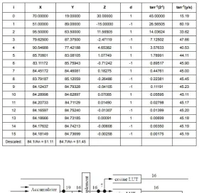
The CORDIC algorithm approaches the target angle by several iterations.
As is showed in the Figure 1, the CORDIC algorithm means transforming a vector (x,y) into a new vector (x ' y '). The basic circular iteration functions of CORDIC algorithm can be seen in formula (1).
From formula (1) the formula (2) can be derived.
If we made the tan(2-i)where i is the current iterative times from 0 to N, then the iterative equation can write:
where di=1,
Ki will be equal to 0.6073 almost when sufficient iteration
steps were computed. So the iteration equation should multiply a gain which computed by the equation (4).
ISSN(Online): 2319-8753 ISSN (Print): 2347-6710
I
nternational
J
ournal of
I
nnovative
R
esearch in
S
cience,
E
ngineering and
T
echnology
(A High Impact Factor, Monthly, Peer Reviewed Journal)
Visit: www.ijirset.com
Vol. 8, Issue 6, June 2019
For every step of the rotation i d is computed as a sign of the i z :
Then the result is
The result is shown in the equation (8) when the initial vector y0 =0.
If X0 is input data of the digital down converter (DDC), the Xn and Yn computed by the NCO are the results of the mixing. When we dose not use the multipliers, we can obtain the mixing data, which can reduce the hardware resources
III. IMPLEMENTATIONINFPGA
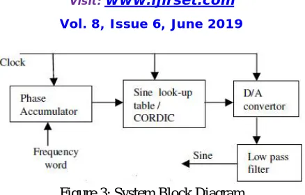
Figure 1 shows the General Block Diagram of CORDIC algorithm based DDFS. It contains following:
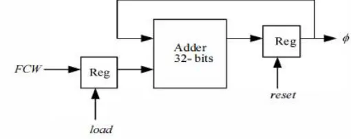
PHASE ACCUMULATOR:
It is used as an index into a waveform lookup table to provide a corresponding amplitude sample.
ISSN(Online): 2319-8753 ISSN (Print): 2347-6710
I
nternational
J
ournal of
I
nnovative
R
esearch in
S
cience,
E
ngineering and
T
echnology
(A High Impact Factor, Monthly, Peer Reviewed Journal)
Visit: www.ijirset.com
Vol. 8, Issue 6, June 2019
Figure 1:Phase Accumulator
ISSN(Online): 2319-8753 ISSN (Print): 2347-6710
I
nternational
J
ournal of
I
nnovative
R
esearch in
S
cience,
E
ngineering and
T
echnology
(A High Impact Factor, Monthly, Peer Reviewed Journal)
Visit: www.ijirset.com
Vol. 8, Issue 6, June 2019
Figure 3: System Block Diagram
The DDFS is one of the requirements in digital modem design.
Particular to our satellite system, we are using BPSK modulation technique, so at transmitter end DDFS can be used in BPSK modulator as shown in fig.6. Input data is used to select the phase and that is added with the phase of the carrier. Finally phase information is converted in to amplitude by CORDIC. D/A is used to get the analog output. The system
can be upgraded to MPSK by suitable selection of phases. At receiver the CORDIC based DDFS finds application in Costas loop demodulator & Bit synchronizer as shown in fig. 4 & 5.
Figure 4: Digital BPSK Modulator
ISSN(Online): 2319-8753 ISSN (Print): 2347-6710
I
nternational
J
ournal of
I
nnovative
R
esearch in
S
cience,
E
ngineering and
T
echnology
(A High Impact Factor, Monthly, Peer Reviewed Journal)
Visit: www.ijirset.com
Vol. 8, Issue 6, June 2019
Figure 6: In phase / Mid phase bit synchronizer
IV. CORDICBASEDDDCFORSATELLITERECEIVER
DDC is one of the important modules of the any receiver system. There are various algorithm to down convert the RF input to any low IF frequency. One of the simple methods is the use of multiplier. For I-Q demodulation we require two multiplier and a DDFS as shown in fig.9.
Figure 6: Multiplier based down conversion
ISSN(Online): 2319-8753 ISSN (Print): 2347-6710
I
nternational
J
ournal of
I
nnovative
R
esearch in
S
cience,
E
ngineering and
T
echnology
(A High Impact Factor, Monthly, Peer Reviewed Journal)
Visit: www.ijirset.com
Vol. 8, Issue 6, June 2019
V.EXPERIMENTRESULTSANDCONCLUSION
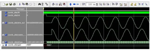
Figure 8: Sin Cos wave simulation results
The simulation result is shown in the above Figure.
VI. CONCLUSION
In this paper a CORDIC-based method for digital down conversion was proposed which overcomes the drawback of the common DDC of requiring a very large ROM table to achieve high resolution. Therefore, it helps to save chip area, power consumption, and costs. Since this CORDIC-DDC can easily be implemented on a pipelined architecture, it is suitable for high speed applications as required for the task of digital down-conversion in software radio terminals. The
CORDICDDC can realize any oscillator frequency by simply feeding it with the appropriate saw-tooth input signal. No coefficients must be changed. Thus, it empowers the software radio concept. An analytically derived worst case quantization error bound was presented which allows an efficient design of
CORDIC-based DDC.
ACKNOWLEDGMENT
The authors wish to thank A, B, C. This work was supported in part by a grant from XYZ.
REFERENCES
[1] Xiaoyuan Wang “Design and Implementation of CORDIC Algorithm Based on FPGA” International Conference on Robots & Intelligent System 2018. India [2] Junwei Li, Jiandong Fang, Bajin Li, “Study of CORDIC Algorithm based on FPGA”, 28th Chinese Control and Decision Conference (CCDC), 2016, China [3] Satish Sharma, Sunil Kulakrni and P. Lakshiminarsimhan “Implementation and Application of CORDIC algorithm in Satellite Communication”.15th National Conference on Communication January2009, Guwahati, India.
[4] Satish Sharma, P. Lakshiminarsimhan, Sunil Kulkarni and Vanitha M “Implementation of Para-CORDIC algorithm and it’s Application in Satellite Communication”. International Conference on Advances in Recent Technologies in Communication and Computing 2009, India
[5] Chang Yong Kang, Earl E.Swartzlander, “An analysis of the CORDIC algorithm for Direct Digital Frequency Synthesis”. IEEE International Conference on Application-Specific system, Architecture and Processors,2002.
[6] Yi-Jiang Cao, Yang Wang and Tze-Yun Sung “A ROM-Less Direct Digital Frequency Synthesizer Based on a Scaling-free CORDIC Algorithm”, The 6th International Forum on strategic technology,2011, Taiwan.
[7] Eugene Grayver, Babak Daneshrad “Direct Digital Synthesis using a modified CORDIC”, integrated circuit and system laboratory,1998.
[8] Shoaib Bhuria, Student Member, IEEE and P.Muralidhar, Member, IEEE “FPGA Implementation of Sine and Cosine Value Generators using Cordic Algorithm for Satellite Attitude Determination and Calculators”,2010.
[9] Ru Xin,Xiao-tong Zhang Han Li, Qin Wang, Zhan-cai Li,” An Area Optimized Direct Digital Frequency Synthesizer Based on Improved Hybrid CORDIC Algorithm.” Information Engineering School, University of Science and Technology Beiging, China,2007.