Design of a Compact Patch-Type Frequency
Selective Surface with Multiple Bands and
Enhanced Bandwidth
Diptargha Baul, Kunal Nandi, Manojit Roy, Partha Pratim Sarkar
Department of Engineering & Technological Studies, University of Kalyani, Kalyani, West Bengal, India
ABSTRACT: This paper deals with the design of a patch type frequency selective surface (FSS). The structure comprises of metallic patches being sandwiched between two dielectric layers of the same material (εr=2.4) and equal thickness (1.6mm). The initial -10dB percentage bandwidth was 2.97%, which eventually is enhanced to 33.60%. The first resonant frequency is decreased by 31.6%, so the design offers more than 50% compactness and in addition, offers multiple bands too.
KEYWORDS:metallic array, array of apertures, resonant frequency, periodic boundary, transmission characteristics, parametric study.
I.INTRODUCTION
A typical frequency selective surface is a two-dimensional metallic array printed on a dielectric slab or array of apertures within a metallic screen, separated by some finite periodicity from each other [1]. When the FSS is illuminated with plane wave, it acts as a microwave filter by allowing some frequencies to transmit through and some to reflect back. Two types of generic geometries of FSS are there. The first one, commonly known as patch-type, acts as a band-reject filter, exhibits total reflection at the resonating frequency, and another type is aperture-type, which exhibits total transmission at resonating frequency, thus performs as a band-pass filter [2]. For an FSS unit cell, there is a relationship between the dimension of the patch and the frequency at which that structure would resonate, involving wavelength. For any periodic surface to have a stable resonant frequency with angle of incidence, the inter-element spacing should be around 0.4 [3]. In recent years, FSSs are used as filters in the wireless communication system [4]. FSSs are usedin airborne radomes, absorbers, and electromagnetic band gap material etc [5].
In this paper, initially an FSS design is proposed which has an extremely large periodic boundary, to attain the practical resonant frequency identical to the calculated one, thus giving an extremely low bandwidth, and ultimately an optimised design is achieved by certain modifications to present a compact-wideband frequency selective surface with multiband operation facility[6-8]. The structures are all simulated in Ansoft designer version 2.
II.FSSUNITCELLDESIGN
The basic FSS unit cell consists of a metallic patch (material copper, dimension 50mm x 25mm and negligible height) sandwiched between two dielectric substrates (material GlassPTFE, height 1.6mm, relative permittivity(εr) 2.4, and
ISSN (Online) : 2319 - 8753
ISSN (Print) : 2347 - 6710
International Journal of Innovative Research in Science, Engineering and Technology
An ISO 3297: 2007 Certified Organization Volume 4, Special Issue 9, July 2015National Conference on Emerging Technology and Applied Sciences-2015 (NCETAS 2015) On 21st & 22nd February, Organized by
Modern Institute of Engineering and Technology, Bandel, Hooghly-712123, West Bengal, India
Fig 1. Proposed Design
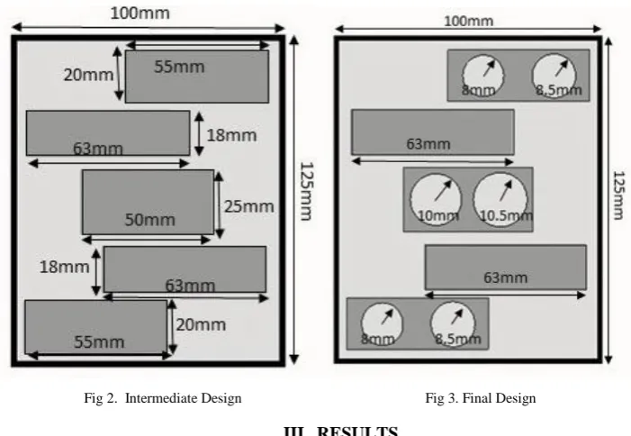
To proceed towards a desired result, an intermediate design is obtained by altering the initial design, with introduction of multiple patches within the periodic boundary as shown in Figure 2.On further modification, the final design is presented, which consists of various circular slots of variable radii over the metallic patches as shown in Figure 3.
Fig 2. Intermediate Design Fig 3. Final Design
III. RESULTS
Fig 4. Transmission Characteristics for the structure shown in figure 1
The transmission characteristic for the intermediate design is shown in Figure 5. It gives three bands. The first resonates at 1.72 GHz having a percentage bandwidth of 1.74%, the second resonates at 1.96 GHz and having a percentage bandwidth of 5.61%, and the third resonates at 2.90 GHz with a percentage bandwidth of 19.66%.
Fig5. Transmission Characteristics for the structure shown in figure 2
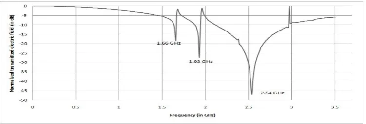
The transmission characteristics obtained for the final design is shown in Figure 6, which also offers a triple band, the first resonating at 1.66 GHz gives a percentage bandwidth of 2.41%, the second resonates at 1.93 GHz and gives percentage bandwidth of 3.63%, and the third band resonates at 2.54 GHz providing a comparatively wide band of percentage bandwidth 33.47%.
ISSN (Online) : 2319 - 8753
ISSN (Print) : 2347 - 6710
International Journal of Innovative Research in Science, Engineering and Technology
An ISO 3297: 2007 Certified Organization Volume 4, Special Issue 9, July 2015National Conference on Emerging Technology and Applied Sciences-2015 (NCETAS 2015) On 21st & 22nd February, Organized by
Modern Institute of Engineering and Technology, Bandel, Hooghly-712123, West Bengal, India
IV.PARAMETRICSTUDY
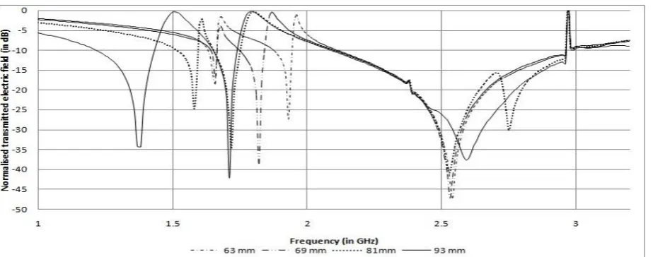
Further a parametric study of the final design is put forward by varying the length of certain patches within the periodic boundary and keeping others constant as shown in Figure 7 and 8. The relative variation of the transmission characteristics is shown in Figure 9.
Fig7. M odified Design Fig 8. Modified Design
Fig 9. Transmission Characteristics of the structure for variation of length of certain patches
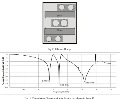
Fig 10. Ultimate Design
Fig 11. Transmission Characteristics for the structure shown in figure 10
The cut-off frequencies, resonant frequencies, bandwidths, and percentage bandwidths attained by this variation of patch-length are summarised in Table 1.
TABLE 1 OBSERVATION TABLE
Patch length Lower
cut-off frequency fL (in GHz)
Resonant frequency fR (in GHz)
Higher cut-off frequency fH (in GHz)
Bandwidth (in GHz) Percentage
Bandwidth
63mm 1.63 1.87 2.11 1.66 1.93 2.54 1.67 1.94 2.96 0.04 0.07 0.85 2.41 3.63 33.47 69mm 1.64
1.75 2.10 1.66 1.82 2.53 1.67 1.84 2.96 0.03 0.09 0.86 1.81 4.95 33.99 81mm 1.52
1.65 2.10 1.58 1.72 2.53,2.75 1.60 1.75 2.96 0.08 0.1 0.86 5.06 5.81 33.99 93mm 1.22
ISSN (Online) : 2319 - 8753
ISSN (Print) : 2347 - 6710
International Journal of Innovative Research in Science, Engineering and Technology
An ISO 3297: 2007 Certified Organization Volume 4, Special Issue 9, July 2015National Conference on Emerging Technology and Applied Sciences-2015 (NCETAS 2015) On 21st & 22nd February, Organized by
Modern Institute of Engineering and Technology, Bandel, Hooghly-712123, West Bengal, India
V. CONCLUSION
Initially the periodic boundary is taken 0.5λ to tally the simulated resonant frequency with the calculated one. As the periodic boundary is extremely large so obviously the bandwidth came out to be extremely narrow with a percentage bandwidth of 2.97% and resonating at 2.02 GHz. By gradual modification of the initial design, three milestones have been reached, firstly three bands have been obtained with all having percentage bandwidth greater than 5%, secondly the resonant frequency of the first band was attained at 1.38 GHz thus giving a left shift of the resonant frequency by 31.68%, which provides an increased compactness by more than 50%, and lastly the third band came out to be quite wide with a percentage bandwidth of 33.60%, resonating at 2.59 GHz. Thus the design may serve as a compact-wideband frequency selective surface with multiband operation facility in L and S band.
REFERENCES
[1] Sung, G.H. Sowerby, K.W. Neve, M.J. Williamson, “A Frequency selective wall for interface reduction in wireless indoor environments”, Antennas and Propagation Magazine, IEEE, Vol. 48, Issue 5, pp.29-37, Oct. 2006.
[2] N.D. Agrawal and W.A. Imbraile, “Design of a Dichoric Cassegrain Sub Reflector”, IEEE Trans, AP-27(4), pp.466-473, 1979. [3] Ben A. Munk, “Frequency selective surfaces Theory and Design”, John Wiley & Sons, pp. 5, 2000.
[4] J.Y. Xue, S.X. Gong, P.F. Zhang, W.Wang and F.F. Zhang, “A new miniaturized fractal frequency selective surface with excellent angular stability”, Progress In Electromagnetic Research Letters, Vol. 13, pp.131-138, 2010.
[5] T.K. Wu, “Frequency selective surface and grid array”, Wiley, New York, 1995.
[6] Surajit Mondal, Gobinda Sen, Tanumay Mandal, Sourav Nandi,Partha Pratim Sarkar, “A Novel Compact-Multiband Frequency Selective Surface”, International Conference on Computation and Communication Advancement (IC3A)-2013.
[7] R.Ghosh, A.Chatterjee, P. Samaddar, A.Pattanayak, D.Sarkar, P.P.Sarkar “Frequency Selective Surfaces: Some
Modifications for Compactness and Bandwidth Enhancement”, National Conference on Computers, Communication & Controls -11 (N4C11), 29th and 30th April 2011.