University of Windsor University of Windsor
Scholarship at UWindsor
Scholarship at UWindsor
Electronic Theses and Dissertations Theses, Dissertations, and Major Papers
6-27-2018
Rotaxane Incorporated Coordination Cages
Rotaxane Incorporated Coordination Cages
Peter Alexander Rowsell
University of Windsor
Follow this and additional works at: https://scholar.uwindsor.ca/etd
Recommended Citation Recommended Citation
Rowsell, Peter Alexander, "Rotaxane Incorporated Coordination Cages" (2018). Electronic Theses and Dissertations. 7480.
https://scholar.uwindsor.ca/etd/7480
This online database contains the full-text of PhD dissertations and Masters’ theses of University of Windsor students from 1954 forward. These documents are made available for personal study and research purposes only, in accordance with the Canadian Copyright Act and the Creative Commons license—CC BY-NC-ND (Attribution, Non-Commercial, No Derivative Works). Under this license, works must always be attributed to the copyright holder (original author), cannot be used for any commercial purposes, and may not be altered. Any other use would require the permission of the copyright holder. Students may inquire about withdrawing their dissertation and/or thesis from this database. For additional inquiries, please contact the repository administrator via email
[2]Rotaxane Incorporated Coordination Cages
by
Peter Alexander Rowsell
A Thesis
Submitted to the Faculty of Graduate Studies through the Department of Chemistry and Biochemistry
in Partial Fulfillment of the Requirements for the Degree of Master of Science
at the University of Windsor
Windsor, Ontario, Canada
2018
[2]Rotaxane Incorporated Coordination Cages
by
Peter Rowsell
APPROVED BY:
__________________________________________________ A. Swan
Department of Biological Sciences
__________________________________________________ J. Rawson
Department of Chemistry & Biochemistry
__________________________________________________ S. Loeb, Advisor
Department of Chemistry & Biochemistry
iii
DECLARATION OF ORIGINALITY
I hereby certify that I am the sole author of this thesis and that no part of this thesis
has been published or submitted for publication.
I performed the synthetic experiments with assistance from Dr. Kelong Zhu and
Dr. Giorgio Baggi. Single-crystal X-ray crystallographic data were collected and
processed with significant assistance from K. Zhu. 2D NMR experiments were
performed and processed with significant assistance from G. Baggi. Association
constant (Ka) calculations were performed with the assistance of G. Baggi. VT NMR data were interpreted with the assistance of Dr. Stephen Loeb.
I certify that, to the best of my knowledge, my thesis does not infringe upon
anyone’s copyright nor violate any proprietary rights and that any ideas,
techniques, quotations, or any other material from the work of other people
included in my thesis, published or otherwise, are fully acknowledged in
accordance with standard referencing practices. Furthermore, to the extent that I
have included copyrighted material that surpasses the bounds of fair dealing within
the meaning of the Canada Copyright Act, I certify that I have obtained a written
permission from the copyright owner(s) to include such material(s) in my thesis
and have included copies of such copyright clearances in my appendix.
I declare that this is a true copy of my thesis, including any final revisions, as
approved by my thesis committee and the Graduate Studies office, and that this
thesis has not been submitted for a higher degree to any other University or
iv ABSTRACT
The interest in molecular machinery has exploded in recent years, as highlighted
by the Nobel Prize in chemistry in 2016 “for the design and synthesis of molecular
machines.” Rotaxanes, specifically molecular shuttles, are a potential component
for the creation of viable molecular machines. Metal-organic frameworks (MOFs)
provide a way to aggregate individual component parts, but their properties are not
easily studied. A coordination cage can mimic the individual pores of a MOF, and
would provide a platform to study a potential molecular machine component.
Taking inspiration from Fujita and Stang’s success by using pyridine and
benzonitrile-based ligands with Pd(II) and Pt(II)-based metal corners to create
molecular polygons, as well as our research group’s success with using rotaxanes
as linkers in MOFs, the [2]-rotaxane ligands [2⸦24C8] and [3⸦24C8] were
designed, synthesized, and characterized. [1⸦24C8] was created by retrosynthetic
analysis to be a molecular shuttle that could easily be converted into a symmetrical
“H-shaped” ligand via replacement of its terminal Br groups. The creation of the
coordination cage [Pd8(dppp)8[3⸦24C8]4][OTf]16 was strongly supported by 1D,
and 2D NMR experiments and was estimated by modeling to have a hydrodynamic
radius of 21.0 Å. Two other molecular cubes, [Pd8(en)8[2⸦24C8]4][NO3]16 and
[Pt8(dppp)8[2⸦24C8]4][OTf]16 were attempted to be synthesized, but
characterization methods were unable to conclusively determine if assembly was
v
DEDICATION
vi
ACKNOWLEDGEMENTS
I would like to thank, first and foremost, Dr. Stephen Loeb for his mentorship over
these years. I would like to thank him for his patience and guidance throughout my
tutelage under him. It is truly an honour and privilege to work for such a great
man. I would also like to thank Dr. Kelong Zhu and Dr. Giorgio Baggi for
supervising much of my lab work. Your mastery of chemistry always amazed and
inspired me. Thank you for being patient and ever-helpful. You both have my
sincere gratitude and respect. To the rest of the Loeb Research Group, many of you
have come and gone over the years and it has been a privilege to meet all of you. It
is always special to be a part of a team working together toward a common goal.
To Dr. Matthew Revington and Dr. Janeen Auld, thank you for always being
approachable and patient. Your guidance and expertise with multiple NMR and
MS experiments, respectively, was invaluable to the completion of this thesis.
To my ever-supportive family and extended family, you have been there with me
through thick and thin. You have helped celebrate my victories and comforted me
in the difficult times. This thesis would have been impossible without you. Mom, I
wish you were here so I could share this with you.
Finally, to my friends, thank you for all the adventures! Thanks for being a
positive outlet when I needed it! Your support, especially in these final months,
has been irreplaceable. Some of you have been as close as family, and I will be
ever-grateful for that. And to my heaven and my hell, my blessing and my curse,
you know who you are. You have earned your spot here as well. Thank you for the
vii
TABLE OF CONTENTS
DECLARATION OF ORIGINALITY ... iii
ABSTRACT ... iv
DEDICATION ...v
ACKNOWLEDGEMENTS ... vi
LIST OF TABLES ...x
LIST OF FIGURES ... xii
LIST OF ABBREVIATIONS/SYMBOLS ... xvi
CHAPTER 1 INTRODUCTION ...1
1.1 Mechanically Interlocked Molecules (MIMs)...1
1.1.1 The Mechanical Bond ...1
1.1.2 Templation ...2
1.1.3 Catenanes ...5
1.1.4 Molecular Knots ...7
1.1.5 Rotaxanes...8
1.1.6 Motion in MIMs ...11
1.2 Motion within Molecular Machines ...15
1.2.1 Motion in Solution ...15
1.2.2 Motion in the Solid State ...16
1.2.3 Monomeric Units That Mimic the Individual Pores of MOFs ...17
viii
1.3.1 Incorporation of Rotaxanes in Coordination Cages ...18
CHAPTER 2: EXPERIMENTAL METHODS ...22
General Comments ...22
2.1 Synthesis of [1⸦24C8] ...23
2.1.1 Synthesis of 4,7-Dibromobenzo-1,2,5-thiadiazole 58 ...23
2.1.2 Synthesis of 3,6-Dibromo-1,2-benzenediamine 59 ...24
2.1.3 Synthesis of 4-(4,7-Dibromo-1H-benzimidazol-2-yl)-benzaldehyde 53 ...25
2.1.4 Synthesis of 4-(4,7-Dibromo-2H-benzimidazol-2-yl)-benzaldehyde∙HBF4 53 ...26
2.1.5 Synthesis of [1⸦24C8] ...27
2.2 Synthesis of ligands ...28
2.2.1 Synthesis of [2⸦24C8] ...28
2.2.2 Synthesis of [3⸦24C8] ...30
2.3 Synthesis of the metal corners ...31
2.3.1 Synthesis of Pd(dppp)Cl260 ...31
2.3.2 Synthesis of Pd(en)(NO3)261 ...32
2.3.3 Synthesis of Pt(dppp)(OTf)256 ...33
2.4 Synthesis of Cages ...34
2.4.1 Synthesis of [Pd8(dppp)8[3⸦24C8]4][OTf]16 ...34
ix
2.4.3 Synthesis of [Pt8(dppp)8([2⸦24C8])4][OTf]16 ...36
CHAPTER 3: RESULTS, DISCUSSION, AND CONCLUSION ...37
3.1 Synthesis and Characterization of the Ligands ...37
3.1.1 Synthesis and Characterization of [1⸦24C8] ...37
3.1.2 Synthesis and Characterization of [2⸦24C8] ...43
3.1.3 Synthesis and Characterization of [3⸦24C8] ...47
3.2 Synthesis and Characterization of the Cages ...52
3.2.1 Synthesis and Characterization of [Pd8(dppp)8[3⸦24C8]4][OTf]16 ...52
3.2.2 Synthesis and Characterization of [Pd8(en)8[2⸦24C8]4][NO3]16 ...65
3.2.3 Synthesis and characterization of [Pt8(dppp)8[2⸦24C8]4][OTf]16 ...68
3.3 Conclusions ...70
3.4 Future Considerations ...72
REFERENCES ...74
APPENDICES ...82
Appendix A – Copyright Permission for Figure 3 ...82
Appendix B – Copyright Permission for Figure 13 ...83
x
LIST OF TABLES
Table 1 – 1H NMR data for 4,7‐dibromobenzo-1,2,5-thiadiazole (CDCl3, 300
MHz) ... 24
Table 2 – 1H NMR data for 3,6-dibromo-1,2-benzenediamine (CDCl3, 300 MHz) ... 25
Table 3 – 1H NMR data for 4-(4,7-dibromo-1H-benzimidazol-2-yl)-benzaldehyde (DMSO-d6, 500 MHz) ... 25
Table 4 – 1H NMR data for 4-(4,7-dibromo-2H-benzimidazol-2-yl)-benzaldehyde∙HBF4 (CD3CN, 500 MHz) ... 26
Table 5 – 1H NMR data for [1⸦24C8] (CDCl3, 500 MHz) ... 28
Table 6 – Important IR spectroscopy data for [1⸦24C8] ... 28
Table 7 – 1H NMR data for [2⸦24C8] (DMSO-d6, 500 MHz) ... 29
Table 8 – Important IR spectroscopy data for [2⸦24C8] ... 29
Table 9 – 1H NMR data for [3⸦24C8] (CDCl3, 500 MHz) ... 31
Table 10 – Important IR spectroscopy data for [3⸦24C8] ... 31
Table 11 – 1H NMR data for Pd(dppp)Cl2 (CD2Cl2, 500 MHz) ... 32
Table 12 – 1H NMR data for Pd(en)(NO3)2 (D2O, 300 MHz) ... 33
Table 13 – 1H NMR data for Pt(dppp)(OTf)2 (CD2Cl2, 300 MHz) ... 34
Table 14 – 1H NMR data for [3⸦24C8] (CDCl3, 500 MHz) ... 35
Table 15 – Important IR spectroscopy data for [Pd8(dppp)8[3⸦24C8] 4][OTf]16 .. 36
Table 16 – Important IR spectroscopy data for [1⸦24C8] ... 43
Table 17 – Important IR spectroscopy data for [2⸦24C8] ... 46
xi
xii
LIST OF FIGURES
Figure 1 – Example of a MIM, Stoddart’s “made to order” [2]catenane 5 ... 2
Figure 2 – An example of Cu(I) being used as a template for the synthesis of a MIM 9 ... 3
Figure 3 – A cartoon illustration of (a) stoichiometric active metal template and (b) catalytic active metal template synthesis of a [2]rotaxane. Reprinted with permission from ref. 7. ... 5
Figure 4 – Stoddart’s “Olympiadane” [5]catenane 14... 6
Figure 5 - An example of the simplest molecular knot, a trefoil knot 23 ... 8
Figure 6 – Cartoons of a pseudorotaxane, semi-rotaxane, and a rotaxane ... 9
Figure 7 – The five general approaches to rotaxane synthesis ... 10
Figure 8 – Example of a [2] rotaxane with only one recognition site 29 ... 11
Figure 9 – Cartoon example of catenane translation in a unidirectional molecular rotor 33 ... 12
Figure 10 – Example of a degenerate molecular shuttle 34 ... 12
Figure 11 – A switchable molecular shuttle 35 ... 14
Figure 12 – Stoddart’s molecular elevator 36 ... 14
Figure 13 – A cartoon illustrating the α-form (left) and β-form (right) of Loeb and Schurko’s 2014 MOF. Reprinted with permission from ref. 45. ... 17
Figure 14 – Examples of previously synthesized H-shaped [2]rotaxane molecular ... 18
Figure 15 – An H-shaped [2]rotaxane used for MOF synthesis 54 ... 19
xiii
Figure 17 – Fujita’s Square 55 ... 20
Figure 18 – Fujita’s coordination boxes from rectangular panel-like ligands 57 .... 21
Figure 19 – 4,7-Dibromobenzo-1,2,5-thiadiazole... 24
Figure 20 – 3,6-Dibromo-1,2-benzenediamine ... 24
Figure 21 – 4-(4,7-Dibromo-1H-benzimidazol-2-yl)-benzaldehyde ... 25
Figure 22 – 4-(4,7-Dibromo-2H-benzimidazol-2-yl)-benzaldehyde∙HBF4 ... 26
Figure 23 – [1⸦24C8] with labeled 1H NMR environments ... 27
Figure 24 – [2⸦24C8] with labeled 1H NMR environments ... 29
Figure 25 – [3⸦24C8] with labeled 1H NMR environments ... 30
Figure 26 – Pd(dppp)Cl2 with labeled 1H NMR environments ... 32
Figure 27 – Pd(en)(NO3)2 with labeled 1H NMR environments... 32
Figure 28 – Pt(dppp)(OTf)2 with labeled 1H NMR environments ... 34
Figure 29 – [3⸦24C8] (left) and Pd(dppp) (right) in [Pd8(dppp)8[3⸦24C8]4][OTf]16 with labelled 1H NMR environments ... 35
Figure 30 – [1⸦24C8] ... 37
Figure 31 – Synthetic scheme for [1⸦24C8] ... 38
Figure 32 – [1⸦24C8] with labeled 1H NMR environments (left) and 13C NMR environments (right)... 41
Figure 33 – 1H NMR spectrum of [1⸦24C8] (CDCl3, 500 MHz) ... 42
Figure 34 – IR Spectrum of [1⸦24C8] ... 42
Figure 35 – Synthetic scheme for [2⸦24C8] ... 43
Figure 36 – [2⸦24C8] with labeled 1H NMR environments ... 44
xiv
Figure 38 – IR spectrum of [2⸦24C8]... 46
Figure 39 – Single-crystal X-ray structure of [2⸦24C8] ... 47
Figure 40 – Synthetic scheme for [3⸦24C8] ... 47
Figure 41 – [3⸦24C8] with labeled 1H NMR environments (left) and 13C NMR environments (right)... 49
Figure 42 – 1H NMR spectrum of [3⸦24C8] (CDCl3, 500 MHz) ... 49
Figure 43 – VT 1H NMR spectra of [3⸦24C8] (CD2Cl2, 300 MHz) showing the variation of the NH peak with temperature ... 51
Figure 44 – IR spectrum of [3⸦24C8]... 52
Figure 45 – [3⸦24C8] (left) and Pd(dppp) (right) in [Pd8(dppp)8[3⸦24C8]4]16+ with labelled 1H NMR environments ... 56
Figure 46 – Stacked 1H NMR spectra of [3⸦24C8] (top), [Pd8(dppp)8[3⸦24C8]4]16+ (middle), and Pd(dppp)Cl2 (bottom), (CD2Cl2, 500 MHz) ... 56
Figure 47 –1H NMR spectrum (aromatic region) of [Pd8(dppp)8[3⸦24C8]4]16+ .... 57
Figure 48 – Labelled NOESY spectrum of [Pd8(dppp)8[3⸦24C8]4]16+ (top and middle: both axes 2.0-13.5 ppm), (bottom: both axes 7.0-9.0 ppm)... 58
Figure 49 – COSY spectrum of [Pd8(dppp)8[3⸦24C8]4]16+ (top 3: both axes = 7.0-9.0 ppm) (bottom: both axes = 1.9-4.0 ppm) ... 60
Figure 50 – DOSY NMR spectrum of [Pd8(dppp)8[3⸦24C8] 4]16+ ... 61
Figure 51 – 31P NMR of [Pd8(dppp)8[3⸦24C8]4]16+ (CD2Cl2, 121.442 MHz) ... 62
xv
Figure 53 – Modeled structure of [Pd8(en)8[3⸦24C8]4]16+ (top: full view) (bottom
left: side-on view) (bottom right: top-down view) ... 65
Figure 54 – Stacked 1H NMR spectra of Pd8(en)8[2⸦24C8]4]16+ (Method 1),
Pd8(en)8[2⸦24C8]4]16+ (Method 2), and[2⸦24C8], (DMSO-d6, 500 MHz) ... 67
Figure 55 – Modeled structure of [Pd8(en)8[2⸦24C8]4][NO3]2 (top: full view)
(bottom left: side-on view) (bottom right: top-down view) ... 68
Figure 56 – Stacked 1H NMR spectra of [2⸦24C8], [Pt8(dppp)8[2⸦24C8]4]16+, and
Pt(dppp)(OTf)2, ([2⸦24C8] and Pt(dppp)(OTf)2:CD2Cl2, 500 MHz) ... 69
Figure 57 – The two most likely energetically favoured aggregations of
Pd(dppp)(OTf)2 and [3⸦24C8] ... 71
Figure 58 – Diagram of tube for growth of crystals (left: hexane layered on top of
the sample in THF) (right: post solvent diffusion, with yellow crystals) ... 72
xvi
LIST OF ABBREVIATIONS/SYMBOLS
º degree(s)
ºC degree(s) Celsius
1D one‐dimensional
1
H proton
2D two‐dimensional
3D three‐dimensional
cm centimeter
δ chemical shift (NMR)
COSY correlation spectroscopy
CSI-MS cold-spray ionization mass spectrometry
d doublet (NMR)
DCM dichloromethane
dd doublet of doublets (NMR)
DFT density functional theory
DMF dimethylformamide
DMSO dimethylsulfoxide
DNA deoxyribonucleic acid
DOSY diffusion ordered spectroscopy
dppp 1,3‐bis(diphenylphosphino)propane
en ethylenediamine
ESI-MS electrospray ionization mass spectrometry
xvii EtOAc ethyl acetate
EtOH ethanol
EXSY exchange spectroscopy
g gram(s)
g/mol gram(s) per mole
h hour(s)
Hz Hertz
IR infrared
J dipole‐dipole coupling constant/scalar (NMR)
m multiplet (NMR)
MeCN acetonitrile
MeNO2 nitromethane
MeOH methanol
mg milligram(s)
min minute(s)
mL milliliter(s)
mL/min milliliter(s) per minute
mmol millimole(s)
MP melting point
MS mass spectrometry
MW molecular weight
nm nanometer
xviii NMR nuclear magnetic resonance
NOE nuclear Overhauser effect
NOESY nuclear Overhauser effect spectroscopy
OTf - trifluoromethanesulfonate anion
Ph phenyl
ppm part(s) per million
RT room temperature
s singlet (NMR)
THF tetrahydrofuran
TLC thin layer chromatography
1 CHAPTER 1
INTRODUCTION
1.1 Mechanically Interlocked Molecules (MIMs)
1.1.1 The Mechanical Bond
In the broad field of chemistry, one may find themselves in any number of diverse
branches. In each one, a researcher would be familiar with one of the bonds defined by
Pauling: the ionic, covalent, and metallic bonds. 1 However, the most recently discovered
bond, the mechanical bond, has opened up unique and beautiful chemical options that are
impossible by only using the “classical” chemical bonds. 2 3
An example of a mechanical
bond can be seen in one of Stoddart’s [2]catenanes in Figure 1. While this bond is still
reliant upon its component parts to contain chemical bonds, the mechanical bond is a
physical interlocking of two or more independent molecular entities such that they cannot
be separated unless a chemical bond is broken within one or more of the aforementioned
component parts. 4 The mechanical bond is something that is familiar to us in the
macroscopic world. One may encounter it in daily life, for example, in clothing, tools, or
décor. By developing a bond that is no longer reliant on electron interactions for bonding
and that is similar in function to something found in the macroscopic world, researchers
have a novel, but familiar, tool in their kit for making molecular machinery that can
2
Figure 1 – Example of a MIM, Stoddart’s “made to order” [2]catenane 5
1.1.2 Templation
In the original attempts to synthesize MIMs, very dilute solutions of component parts
were added together and ring closing reactions carried out. This method of synthesis
results in extremely poor yields (usually less than 1%), as one can only hope statistically
that the rings close around the desired substrate rather than closing independently.
Template-directed synthetic methods remove the guesswork from the formation of
MIMs. For instance, Cu(I) templated catenanes have been made in yields above 90%. 6
Templation can be used for the synthesis of various MIMs such as: catenanes, molecular
3
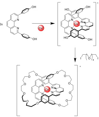
Figure 2 – An example of Cu(I) being used as a template for the synthesis of a MIM 9
Within templation synthetic methods, there are two types: passive and active. Although
both methods use various intermolecular interactions such as ion-ion, ion-dipole, and
hydrogen bonding to promote mechanical bond formation, the majority of cases uses
metal ion coordination for templation. 8 In passive templation, a “template” interacts with
functional groups on the component parts in solution. 7 8 From a design perspective, this
requires that the component parts be functionalized such that the templation interaction
will occur to create desirable overlap during the subsequent ring closing steps (as seen in
4
synthesis, active templation has further built upon the foundation passive templation
created. 7 Active templation takes templation a step further by not only using a template
to promote the correct positioning of component parts, but also promoting covalent bond
formation to complete the mechanical bond (as seen in Figure 3). 7 The template interacts
with the cavity of the macrocycle, and it promotes bonding of a secondary component
through the ring. This provides an advantage over passive templation since permanent
recognition sites are no longer required on the component parts, thus allowing more
creative options in molecular design. Additionally, active templation reactions can be
carried out in a catalytic fashion, where only sub-stoichiometric amounts of template are
needed; 11 whereas, passive templation always requires at least a stoichiometric amount of
templating ion. 7 10 In summary, template-directed synthetic methods have allowed the
making of MIMs to grow from a niche idea, to a mainstream Nobel-prize-winning field
with the potential to radically affect our future through the creation of molecular
5
Figure 3 – A cartoon illustration of covalent bond formation between “half-thread” units (shown in orange and green) promoted through a macrocycle (shown in blue) to generate
a rotaxane as promoted by a metal catalyst (shown as a grey ball). (a) Stoichiometric active metal template and (b) catalytic active metal template synthesis of a [2]rotaxane. Half-thread units: orange and green. Metal catalyst: grey ball. Reprinted with permission
from ref. 7.
1.1.3 Catenanes
When discussing MIMs, perhaps the most obvious example is the catenane—a complex
which usually consists of two or more macrocycles mechanically bonded. In fact, the
very first successful synthesis of a mechanical bond was a [2]catenane made by
Wasserman in 1960. 13 Since then, higher ordered discrete structures such as Stoddart’s
“Olympiadane” [5]catenane (see Figure 4) 14
, and polymer chain-like [n]catenanes have
been synthesized. 15 In a somewhat unique twist on classic macrocyclic catenanes, there
are even examples of interlocked molecular cage catenanes. 16 17 Not only can catenanes
be used to create interesting molecular topologies, but they can also be used as
6
(360° rotation of a single ring, relative position of the rings), as well as their ability to
create cavities with interlocked rings, make these molecules candidates for molecular
switches, motors, and sensors. 18
7 1.1.4 Molecular Knots
Perhaps the most beautiful examples of MIMs are molecular knots. Knots are common
structures in our macroscopic world, but envisioning them on a molecular scale requires a
unique chemical perspective. Molecular knots are defined by how many “crossing points”
there are in the structure. The simplest example of a molecular knot, a trefoil knot, must
have 3 crossings, as seen in Figure 5. 19 By using a variety of templating methods, more
complex molecular knots with up to 8 crossings have been successfully synthesized. 20 As
significant as our advancements have been in the synthesis of these knots, nature still far
outpaces human advancement with its knots in proteins and DNA. 19 Structure is related
to function in biological systems, therefore these knots end up having functional
ramifications. In cells, DNA has to be tightly packed so that it can be long enough to
carry the necessary genetic information for an organism; however, in this tightly packed
system, knotting can occur which can cause significant deleterious effects for an
organism. 21 When researchers incubated topoisomerase I from E. coli and DNA together,
it was found that every possible knot up to seven crossings was created. 22 While the field
of molecular knots is growing, it has not yet had as great an impact on molecular
8
Figure 5 - An example of the simplest molecular knot, a trefoil knot 23
1.1.5 Rotaxanes
One final MIM to be discussed, and the one most important to this thesis, is the rotaxane
– a molecule which consists of a “wheel” (a macrocycle) and an “axle” (a linear molecule
with bulky stoppers on the ends, i.e. a “dumbbell”). As can be seen in Figure 6, there are
two forms of precursors related to rotaxanes that can exist, the pseudorotaxane and the
semi-rotaxane. The pseudorotaxane lacks the bulky stopper groups (as represented by the
grey balls) on the ends of the molecule, and the semi-rotaxane which just has one stopper
group, rather than two. The pseudorotaxane and semi-rotaxane are described as
interpenetrated as the wheel can still easily unthread from the axle whereas the rotaxane
9
Figure 6 – Cartoons of a pseudorotaxane, semi-rotaxane, and a rotaxane
As mentioned in 1.1.2, template-directed synthetic methods allowed rotaxanes to be
synthesized reliably and in good yields. 7 As seen in Figure 7, there are five main
template-directed mechanisms which can be followed to synthesize rotaxanes. “Capping”
first creates a pseudorotaxane, and then adds bulky stopper groups on the ends. 25
“Snapping” independently creates a semi-rotaxane and the other half of the axle, and then
joins the two pieces. 26 “Clipping” makes the naked dumbbell first, then a ring closing
reaction is performed around the axle. 27 “Slipping” uses elevated temperatures to cause
the macrocycle to enlarge, thus being able to slip over the stopper groups of the naked
dumbbell. 28 Finally, active templation not only aligns the two halves of the axle and the
macrocycle, but also promotes covalent bond formation through the ring. 7 Pseudorotaxane Semirotaxane
10
Figure 7 – The five general approaches to rotaxane synthesis
The simplest rotaxanes are [2]rotaxanes that have only one recognition site for the
macrocycle to bind. As can be clearly seen in Figure 8, the large dumbbell groups prevent
the wheel from unthreading from the axle. In this example from Loeb, the type of
rotaxane in Figure 8 is used as a ligand for MOF synthesis and the rotation of the wheel is
used for complexation to metal ions. 29 By expanding the linker between the two stoppers
and adding additional recognition sites, a molecular shuttle can be created. Further
discussion on the motion found in rotaxanes can be found in section 1.1.6. Both this
rotation and translation make rotaxanes potential molecular machine components. 30 1) Capping
2) Snapping
3) Clipping
4) Slipping
11
Figure 8 – Example of a [2] rotaxane with only one recognition site 29
1.1.6 Motion in MIMs
Dynamic motion in MIMs is the most important feature for their development into
molecular machines. In both catenanes and rotaxanes, the macrocyclic wheel will
undergo rotational motion with respect to the other component. 31 32 Catenanes rotate one
ring relative to the other ring, and in rotaxanes the wheel and axle rotate relative to each
other. 31 32 By functionalizing the rings on a catenane and making recognition sites
sensitive to an outside stimulus, a unidirectional molecular rotor can be made, as seen in
Figure 9. 33 Stepwise reaction can be undergone to make certain binding sites more
favourable to allow one ring to “travel” around the other ring. 33 For rotaxanes, the wheel
and dumbbells can also be functionalized to potentially create molecular motors;
12
Figure 9 – Cartoon example of catenane translation in a unidirectional molecular rotor 33
Figure 10 – Example of a degenerate molecular shuttle 34
50% 50%
Statistical distribution of the macrocycle Brown Green
Purple Blue
Ka(Green)>Ka(Blue)>Ka(Yellow)
Ka(Blue)>Ka(Yellow)>Ka(Brown) Ka(Yellow)>Ka(Brown)>Ka(Purple
)
Green Brown
13
A second type of dynamic motion can also take place, called translation. In 1991,
Stoddart discovered that if an unsaturated rotaxane was made (i.e. there are more
recognition sites than wheels to bind to them), the macrocycle will shuttle between
binding sites or “stations” rather than just spinning in place. 34
Furthermore, it was found
that if these stations are equivalent, the macrocycle will be evenly distributed between
both stations (see Figure 10). 34 By making the stations different and sensitive to other
stimuli, the statistical distribution of the macrocycle can be manipulated. 24 In 1994,
Stoddart created a switchable molecular shuttle (see Figure 11). 35 By protonating one of
the stations for the shuttle, it makes the other station more favourable, and the wheel
shuttles to the other site. 35 Since then, different molecular shuttles have been designed
that use light, solvent, pH, and electrical current as stimuli to control shuttling of the
macrocycle. 24 The motion in molecular shuttles, as well as their ability to be controlled,
makes them ideal components for molecular machines. 24 For example, Stoddart’s
“molecular elevator,” as seen in Figure 12, uses acid-base chemistry to move a
platform-like shuttle between two stations. 36 It uses the same principles as the simpler molecular
shuttles – when one of the stations is deprotonated, the electron-rich ring shuttles to the
other more electron-poor station. By utilizing the dynamic properties of rotaxanes and
pseudorotaxanes, numerous molecular machine components such as switches, 37 logic
gates, 38 sensors, 39 nanovalves, 40 nanomotors, 41 elevators 36, and molecular ratchets 42
have been synthesized. Due to their ability to be made consistently with good yields, and
their internal dynamic motion, rotaxanes continue to be on the forefront of molecular
14
Figure 11 – A switchable molecular shuttle 35
Figure 12 – Stoddart’s molecular elevator 36
84% 16%
Statistical distribution of the macrocycle
<2% 98%
15
It is only by finally controlling this motion in MIMs that researchers can make significant
steps into the field of molecular machinery. 43 Unidirectional dynamic motion can be
achieved with catenanes-based machines, whereas molecular shuttles must actuate. This
makes catenanes more suitable for molecular motor-like components and rotaxanes more
suitable for molecular switch-like components. 30
1.2 Motion within Molecular Machines
1.2.1 Motion in Solution
While the ability to do work exists for both catenanes and rotaxanes, due to their rings
having a wide range of motion; in solution, this motion is often random and difficult to
predictably control. 30 Brownian motion of the macrocycles must be suppressed in order
to make a predictable system. This can be done by using the stimuli-responsive systems
mentioned above. Solution chemistry of MIMs allows free motion of their component
parts, so the dynamic properties of the complexes can be studied. 44 Properties such as
shuttling rates in rotaxanes, binding affinity for recognition sites in catenanes and
rotaxanes, response rates to stimuli, quantitative measurements about which binding site
is preferred, all can be determined in solution by methods such as NMR spectroscopy and
fluorescence spectroscopy. 30 Dynamic properties of MIMs are easily determined in
solution and those properties are critical for knowing how much work could potentially
be performed by a system. However, in order to make viable molecular machines, a
series of component parts must be linked together, as well as controlled, to do work in the
same net direction. 30 In solution, components are randomly dispersed, randomly oriented,
16
phases or the solid state is better suited for functional organization of these component
parts. 45
1.2.2 Motion in the Solid State
While solution chemistry offers the ability to test the mechanical properties of a MIM,
the solid state offers the ability to assemble an array of MIMs into a potential molecular
machine that could perform significant work. 30 MOFs are crystalline polymers that
utilize metal-ligand self-assembly reactions to create porous molecular lattices. 46 MOFs
are made from labile metal-ligand combinations, so the structure is self-correcting during
synthesis. 46 Another interesting attribute of MOFs is that they can undergo host-guest
chemistry within their pores. 46 The size of the pores can select for the size and shape of
the guest molecules that will enter them. 46 MOFs provide an excellent basis for the
organization of MIMs since their frameworks can be rigid and robust. 47 An important
step towards this reality came when it was found that rotaxanes could be used as
ligands. 48 This idea led to the formation of metal-organic frameworks (MOFs) that
incorporated rotaxanes. 44 The demonstration that organization could be straightforward
and consistent in the solid state was a breakthrough for molecular machines. After
organization, control needed to be addressed. In 2014, Loeb and Schurko demonstrated
not only the creation of a novel MOF, but also that ring rotation could be controlled by a
reversible phase change. 45 When the MOF was in the α-form (left in Figure 13), the ring
is locked in place, while in β-form (right in Figure 13) the full range of motion for the
macrocycle is available. 45 This allows for “on” and “off” states in the system. 45 49 While
17
machines, characterization is challenging and individual pores of a MOF cannot be
studied.
Figure 13 – A cartoon illustrating the α-form (left) and β-form (right) of Loeb and Schurko’s 2014 MOF. Reprinted with permission from ref.45.
1.2.3 Monomeric Units That Mimic the Individual Pores of MOFs
A potential solution to overcome the characterization problem of MOFs, is to create
individual units that could be characterized in solution and then converted into a MOF
system. The closest monomeric units that are comparable to MOFs are coordination
cages. Coordination cages are made by the same metal-ligand self-assembly approach as
MOFs, but have additional “corner” groups on the metal which cannot be replaced and
therefore prevent polymerization. 50 Just like MOFs, these compounds also undergo
host-guest chemistry and can be designed to selectively incorporate certain host-guest
compounds. 50 By considering the binding angles of a ligand, the preferred geometry of
the metal, and the number of available binding sites on each, one can predict the
geometry of the synthesized cage. 51 Furthermore, one can decorate the ligands of the
cage with functional groups to further dictate the characteristics of the cavity of the cage.
Since coordination cages are analogous to a single unit of a MOF and can be isolated and
fully characterized in solution, they can be utilized as small-scale testing beds for the
18 1.3 Scope of This Thesis
1.3.1 Incorporation of Rotaxanes in Coordination Cages
Figure 14 – Examples of previously synthesized H-shaped [2]rotaxane molecular shuttles 5253
It has been found that rotaxanes can be used as ligands and incorporated into MOFs, but
their large crystalline polymeric networks make testing the properties of individual pores
difficult. 44 Large H-shaped rotaxanes have already been synthesized, as seen in Figure
14. 52 53 This rotaxane shape showed promise as a ligand due to its bond angles
potentially being 90° and its ability to create rigid pillars in MOFs. 52 53 Loeb and
coworkers have already incorporated an H-shaped rotaxane into a MOF by using
carboxylic acid terminal groups. 54 The [2]rotaxanes used (as seen in Figure 15)
undergoes shuttling inside a MOF and is a stepping stone to an organized array of
molecular switches. 54 In order to better understand the behaviour of individual pores of
the MOF, ligands needed to be designed that would create single cage molecules rather
than MOFs. By simply changing the terminal groups on the molecule to pyridine and
19
and [3⸦24C8] were designed. These ligands should both create assemblies that mimic
the shape of the pores and motion of the molecular shuttles in the aforementioned MOF.
Figure 15 – An H-shaped [2]rotaxane used for MOF synthesis 54
20
Figure 17 – Fujita’s Square 55
The early precursor to the development of coordination cages came from the
development of simpler molecular polygons – 2D and then 3D. In particular, Fujita
incorporated 90° angles into metal-ligand assemblies. 55 His research group successfully
made a molecular square by using a (en)Pd(II) metal corner and 4,4’-bipyridine ligands
(see Figure 17). 55 Expanding on Fujita’s work, Stang used (dppp)Pd(II) metal corners,
and ligands with pyridine groups or nitrile terminal groups to make comparable squares
and rectangles. 56 Fujita further showed in 2001 that a slightly larger tetradentate ligand
with pyridyl coordinating groups could be used to make “coordination boxes” with
(en)Pd(II) metal corners (Figure 18). 57 These complexes used rigid ligands as “panels”
for making 3D polygons. 57 These successful geometric assemblies were a significant
factor when deciding on what terminal groups to place on our new rotaxane ligands. The
panels of this box offer a blueprint for the ligands synthesized in this thesis, [2⸦24C8]
and[3⸦24C8], which are both rigid H-shaped tetradentate ligands (as seen in Figure 16).
This thesis therefore aims to combine the self-assembly principles of Fujita’s rigid
tetradentate ligands and Loeb’s concept of using rotaxanes as ligands to produce a
21
Furthermore, from a molecular machine design perspective, the packing of rotaxanes in
the novel coordination cage may allow some interactions between rotaxane wheels and
the possibility for the study of cooperative motion.
22
CHAPTER 2: EXPERIMENTAL METHODS
General Comments
All reagents and starting materials were commercial grade and purchased from
Sigma-Aldrich, Alfa Aesar, or Strem Chemicals Inc. They were used without further
purification. 4,7-dibromobenzo-1,2,5-thiadiazole, 3,6-dibromo-1,2-benzenediamine, 4-(4,
7-dibromo-1H-benzimidazol-2-yl)-benzaldehyde, 4-(4,7-dibromo-2H-benzimidazol-2-yl)
-benzaldehyde∙HBF4, Pd(dppp)Cl2, Pd(en)(NO3)2, and Pt(dppp)(OTf)2, were prepared
using literature procedures. For completeness and continuity within the Loeb Research
Group, the preparation and basic characterization for each of these compounds are
described herein and individual references provided with the preparative description.
Deuterated solvents were purchased from Cambridge Isotope Laboratories and used
without further purification. Organic solvents were dried using an Innovative
Technologies Solvent Purification System. Thin Layer Chromatography (TLC) was
performed using Teledyne Silica gel 60 F254 plates and viewed under UV light. Melting
point data were collected on a OptiMelt MPA100 melting point apparatus. IR spectra
were collected on a Bruker Alpha FTIR spectrometer with a Single reflection ATR
QuickSnap™ sampling module. 1H NMR spectra were collected on a Bruker DPX 300
spectrometer with a working frequency of 300 MHz and a Bruker Avance III
spectrometer with a working frequency of 500 MHz. 13C NMR spectra were collected on
a Bruker Avance 300 spectrometer with a working frequency of 75.43 MHz and a 500
MHz Bruker Avance III with a working frequency of 125.72 MHz. 1H and 13C chemical
shifts are reported in ppm relative to tetramethylsilane, using the residual solvent peak as
23
spectrometer with a working frequency of 121.442 MHz. Chemical shifts are reported in
ppm relative to a solution of phosphoric acid (80%) in D2O and using the residual solvent
peak as a reference standard. High resolution mass spectrometry (HR-MS) experiments
were performed on a Micromass LCT electrospray ionization (ESI) time-of-flight (ToF)
mass spectrometer. Solutions with concentrations of 0.001 molar were prepared in
methanol and injected for analysis at a rate of 5 μL/min using a syringe pump. Single
crystal X-ray data were collected on a Bruker D8 Venture diffractometer, equipped with a
PHOTON 100 detector, Kappa goniometer, and a Mo sealed tube source. Crystals were
frozen in paratone oil inside a cryoloop and reflection data were integrated using APEX
III software. Molecular models were constructed using the program Scigress from Fujitsu
using molecular mechanics (MM3) calculations.
2.1 Synthesis of [1⸦24C8]
2.1.1 Synthesis of 4,7-Dibromobenzo-1,2,5-thiadiazole 58
2,1,3-Benzothiadiazole (5.01 g, 36.8 mmol, MW = 136.17 g/mol) and N-
bromosuccinimide (NBS) (13.54 g, 76.1 mmol, MW = 177.98 g/mol) were added to a
round bottom flask. H2SO4 (50 mL) was added to the solids in the flask. After the solids
dissolved, the mixture was stirred at 60˚C for 3 h. The flask was then cooled to room
temperature, and placed in an ice bath. Cold H2O (250 mL) was added in small portions.
The product was extracted with toluene (3 x 300 mL). The organic layers were dried over
anhydrous Na2SO4, and filtered. The organic solvent was removed by rotary evaporator
leaving an off-white solid product.
24
Figure 19 – 4,7-Dibromobenzo-1,2,5-thiadiazole
Proton δ (ppm) Multiplicity # of Protons J (Hz)
a 6.79 s 2 --
Table 1 – 1H NMR data for 4,7‐dibromobenzo-1,2,5-thiadiazole (CDCl3, 300 MHz)
2.1.2 Synthesis of 3,6-Dibromo-1,2-benzenediamine 59
4,7-Dibromobenzo-1,2,5-thiadiazole (2.0 g, 6.8 mmol, MW = 293.97 g/mol) was
dissolved in EtOH (50 mL). The mixture was cooled to 0˚C, then NaBH4 (10 g, 264.0
mmol, MW = 37.83 g/mol) was added slowly. After addition, the reaction mixture was
slowly warmed to room temperature and then it was stirred overnight at room
temperature. The solvent was then evaporated and the resulting orange solids dissolved in
diethyl ether and washed three times with water and brine. The organic layer was dried
over anhydrous MgSO4 and filtered. Removal of solvent produced a beige solid.
Yield: 1.41 g, 80%, MW = 265.9 g/mol
25
Proton δ (ppm) Multiplicity # of Protons J (Hz)
a 6.86 s 2 --
b 3.90 s 4 --
Table 2 – 1H NMR data for 3,6-dibromo-1,2-benzenediamine (CDCl3, 300 MHz)
2.1.3 Synthesis of 4-(4,7-Dibromo-1H-benzimidazol-2-yl)-benzaldehyde 53
3,6-Dibromo-1,2-benzenediamine (2.3 g, 8.7 mmol, MW = 265.90 g/mol) and
1,4-dicarboxyaldehyde (5.8 g, 43.3 mmol, MW = 134.13 g/mol) were added to a 500 mL
round bottom flask. Acetonitrile (200 mL) was added and the mixture stirred for 10 min.
ZrCl4 (0.1 g, 0.43 mmol, MW = 233.04 g/mol) was added and the reaction mixture was
stirred at room temperature in the open air for 2 days. The resulting mixture was filtered.
The solids were washed with hot acetonitrile then collected and dried. To obtain more
product, the filtrate was concentrated to 50 mL and the solid that precipitated was
collected. The collected product fractions were light yellow.
Yield: 2.60 g, 80%, MW = 380.0 g/mol
Figure 21 – 4-(4,7-Dibromo-1H-benzimidazol-2-yl)-benzaldehyde
Proton δ (ppm) Multiplicity # of Protons J (Hz)
a 13.56 s 1 --
b 10.10 s 1 --
c 8.56 d 2 8.0
d 8.11 d 2 8.0
e, f 7.43 s 2 --
26
2.1.4 Synthesis of 4-(4,7-Dibromo-2H-benzimidazol-2-yl)-benzaldehyde∙HBF4 53
4-(4,7-Dibromo-1H-benzimidazol-2-yl)-benzaldehyde (216 mg, MW = 380.0 g/mol,
0.568 mmol) was stirred in acetonitrile (5 mL). HBF4∙Et2O (93 μL, MW = 161.94 g/mol,
0.682 mmol) was added to the mixture until a clear solution resulted. The mixture was
stirred for 10 min, and then Et2O was added until no more solid precipitated from
solution. Solids were collected by vacuum filtration, washed with Et2O, and air dried.
Yield: 252 mg, 95%, MW = 467.85 g/mol
Figure 22 – 4-(4,7-Dibromo-2H-benzimidazol-2-yl)-benzaldehyde∙HBF4
Proton δ (ppm) Multiplicity # of Protons J (Hz)
a -- -- -- --
b 10.18 s 2 --
c 8.31 d 2 10.0
d 8.24 d 2 10.0
e 7.74 s 2 --
27 2.1.5 Synthesis of [1⸦24C8]
4-(4,7-Dibromo-2H-benzimidazol-2-yl)-benzaldehyde∙HBF4 (405 mg, MW = 467.85
g/mol, 0.87 mmol), and 24-crown-8-ether (458 mg, MW = 352.42 g/mol, 1.30 mmol)
were dissolved in CHCl3/MeCN (56 mL/14 mL). 4,7-Dibromobenzo-1,2,5-thiadiazole
(230 mg, MW = 265.9 g/mol, 0.87 mmol) was added and stirred until a clear yellow
solution resulted. ZrCl4 (20 mg, MW = 233.04 g/mol, 0.087 mmol) was added, and the
reaction was stirred in air at room temperature for 24 h. Solvent was removed by rotary
evaporator and the solids were washed with Et2O (3 x 25 mL). Next, the resulting solids
were extracted with hot CH3CN (3 x 30 mL), and the combined organic extracts were
basified with Et3N (1 mL). The solids that precipitated from solution were collected by
vacuum filtration. The filtrate was concentrated by removing half of the solvent; and the
flask was placed in the freezer for 1 h. Any further solids precipitated out of solution
were collected by vacuum filtration. 13C NMR (CDCl3, 75.49 MHz) δ (ppm): 153.1,
143.3, 135.0, 130.6, 128.9, 128.9, 126.3, 126.1, 112.3, 102.4, 70.0
Yield: 465 mg, 55% MW = 978.37 g/mol
Exact Mass = 974.9809 (theo.), 974.9814 (exp.) Melting Point = 319 °C (decomposed)
28
Proton δ (ppm) Multiplicity # of Protons J (Hz)
a 11.26 s 2 --
b, c 8.67 s 4 --
d 7.37 d 2 9.0
e 7.28 d 2 9.0
f 3.47 s 32 --
Table 5 – 1H NMR data for [1⸦24C8] (CDCl3, 500 MHz)
Functional Group
Wavenumber (cm-1)
Amine N-H 3189
Aromatic C-H 2865 Aromatic C-C 1436
Amine C-N 1174
Crown ether C-O 1085 Aromatic C-H 930 Aromatic C-H 863
Amine N-H 792
C-Br 759
Table 6 – Important IR spectroscopy data for [1⸦24C8]
2.2 Synthesis of ligands
2.2.1 Synthesis of [2⸦24C8]
[1⸦24C8] (300 mg, MW = 978.37 g/mol, 0.31 mmol), 4-pyridinylboronic acid (188 mg,
MW = 122.9 g/mol, 1.5 mmol), 2M Na2CO3 (30 mL, MW = 105.99 g/mol, 61 mmol),
and THF (40 mL) were added to a Schlenk flask. The mixture was degassed for 1 h by
bubbling N2 through the solution. The catalyst PEPPSI-IPr (20 mg, MW = 679.46 g/mol,
0.031 mmol) was added to the degassed reaction mixture and the solution was refluxed
overnight under a N2 atmosphere. The solvent was then removed by rotary evaporator.
The resulting solids were extracted with CH3Cl (3 x 20 mL) and brine (20 mL). The
organic phase was collected and dried over anhydrous Na2SO4, and filtered. Solvent was
29
Yellow solids were collected by vacuum filtration and air dried. Crystals were obtained
from slow evaporation of THF.
Yield: 213 mg, 72% MW = 971.11 g/mol
Exact Mass = 971.4450 (theo.), 971.4446 (exp.) Melting Point >400 °C (decomposed)
Figure 24 – [2⸦24C8] with labeled 1H NMR environments
Proton δ (ppm) Multiplicity # of Protons J (Hz)
a 12.52 s 2 --
b 8.79 d 4 5.0
c 8.73 d 4 5.0
d, e 8.65 s 4 --
f 8.36 d 4 5.0
g, h 7.76 m 6 --
i 7.46 d 2 7.5
j 3.14 s 32 --
Table 7 – 1H NMR data for [2⸦24C8] (DMSO-d6, 500 MHz)
Functional Group
Wavenumber (cm-1) Aromatic C-H 2870 Aromatic C-C 1595 Aromatic C-C 1443
Amine C-N 1254
Crown ether C-O 1100 Aromatic C-H 801
Amine N-H 725
30 2.2.2 Synthesis of [3⸦24C8]
[1⸦24C8] (50 mg, MW = 978.37 g/mol, 0.051mmol), 4-cyanophenylboronic acid
(45.1 mg, MW =146.94 g/mol, 0.31 mmol), 2M Na2CO3 (5 mL, MW = 105.99 g/mol,
10 mmol), and THF (20 mL) were added to a Schlenk flask. The mixture was degassed
for 1 h by bubbling N2 through the solution. Pd(Ph3P)4 (35.4 mg, MW = 1155.6 g/mol,
0.031 mmol) was added to the degassed reaction mixture and the solution was refluxed
overnight under a N2 atmosphere. The organic solvent was then removed by rotary
evaporator. The resulting solids were extracted with CH3Cl (3 x 5 mL) and brine (5 mL).
The organic phase was dried over anhydrous Na2SO4, and filtered. Solvent was removed
by rotary evaporator, then the resulting solids were refluxed in CH3CN (5 mL). Pale
yellow solids were collected by vacuum filtration and air dried. 13C (CDCl3, 75.49 MHz)
δ (ppm): 153.5, 143.4, 143.0, 142.8, 133.3, 133.0, 132.3, 131.4, 130.3, 130.3, 129.5,
129.0, 124.5, 123.7, 122.2, 119.4, 118.8, 111.6, 110.8, 69.9
Yield: 40.9 mg, 75% MW = 1067.22 g/mol
Exact Mass =1067.4450 (theo.), 1067.4459 (exp.) Melting Point >400 °C (decomposed)
31
Proton δ (ppm) Multiplicity # of Protons J (Hz)
a 10.81 s 2 --
b, c 8.59 s 4 --
d 8.47 d 4 8.5
e, f, g 7.87 m 12 --
h 7.62 d 2 8.0
i 7.39 d 2 8.0
j 3.22 s 32 --
Table 9 – 1H NMR data for [3⸦24C8] (CDCl3, 500 MHz)
Functional Group
Wavenumber (cm-1)
Amine N-H 3295
Aromatic C-H 2920 Nitrile CΞN 2223 Aromatic C=C 1601
Amine C-N 1258
Crown ether C-O 1089 Aromatic C-H 851
Table 10 – Important IR spectroscopy data for [3⸦24C8]
2.3 Synthesis of the metal corners
2.3.1 Synthesis of Pd(dppp)Cl2 60
PdCl2 (200 mg, MW = 177.33 g/mol, 0.0011 mol) was refluxed overnight in MeCN
(10 mL, MW = 41.05 g/mol, ρ = 0.786 g/mL, 0.19 mol) under a N2 atmosphere. The
reaction mixture was filtered and the solids were washed with Et2O (3 x 5 mL) and air
dried to yield Pd(MeCN)Cl2 (275.0 mg, 95%). The Pd(MeCN)Cl2 (275 mg, MW =
259.43 g/mol, 0.0011 mol) were directly added to a Schleck flask with dppp (481 mg,
MW = 412.44 g/mol, 0.0012 mol) and benzene (10 mL). The reaction flask was degassed
32
for 24 h. The reaction mixture was filtered and the collected solids were washed with
cold benzene (3 x 5 mL) to give Pd(dppp)Cl2.
Yield: 556 mg, 85% MW = 589.77 g/mol
Figure 26 – Pd(dppp)Cl2 with labeled 1H NMR environments
Proton δ (ppm) Multiplicity # of Protons J (Hz)
a 7.76 m 8 --
b 7.52 m 4 --
c 7.45 m 8 --
d 2.41 m 4 --
e 2.00 m 2 --
Table 11 – 1H NMR data for Pd(dppp)Cl2 (CD2Cl2, 500 MHz)
2.3.2 Synthesis of Pd(en)(NO3)261
AgNO3 (143 mg, MW = 169.87 g/mol, 0.84 mmol) was dissolved in H2O (20 mL) in a
flask. Pd(en)Cl2 (100 mg, MW = 237.42 g/mol, 0.42 mmol) was added and the reaction
mixture was stirred at room temperature for 1 h at 50˚C. A white precipitate of AgCl was
filtered off, and solvent was evaporated from the filtrate to isolate [Pd(en)(NO3)2] as a
pale yellow solid.
Yield: 88 mg, 70%, MW = 290.53 g/mol
33
Proton δ (ppm) Multiplicity # of Protons J (Hz)
a 4.66 s 4 --
b 2.45 s 4 --
Table 12 – 1H NMR data for Pd(en)(NO3)2 (D2O, 300 MHz)
2.3.3 Synthesis of Pt(dppp)(OTf)2 56
K2[PtCl4] (300 mg, MW = 415.09 g/mol, 0.72 mmol) was dissolved in H2O (2.5 mL) in a
small vial. Propionitrile (0.3 mL, MW = 55.08 g/mol, ρ = 0.77 g/mol, 4.20 mmol) was
added to the vial, and the mixture stood at room temperature for 3 days. The yellow
rod-like crystals were collected via vacuum filtration, washed with H2O (3 x 5mL), and dried
in an oven at 70 ˚C. The collected PtCl2[(C2H5CN)2] (234 mg, 86%) crystals were used
directly for the next step of synthesis.
PtCl2[(C2H5CN)2] (234 mg, MW = 376.15 g/mol, 0.62 mmol) was placed in a Schlenk
flask, then evacuated and backfilled with N2 three times. Dry and degassed DCM (5 mL)
was added to the flask to dissolve the solids. 1,3-Bis(diphenylphosphino)propane
(257 mg, MW = 412.44 g/mol, 0.62 mmol) was placed in another Schlenk flask, then
evacuated and backfilled with N2 three times. Dry and degassed DCM (5 mL) was added
to the flask to dissolve the solids. The contents of flask 2 were transferred to flask 1 and
the reaction mixture was stirred overnight at room temperature under N2. The resulting
solids were collected via vacuum filtration and washed with Et2O (3 x 5 mL). The
collected Pt(dppp)Cl2 (363 mg, 86%) was used directly for the next step of synthesis.
Pt(dppp)Cl2 (363 mg, MW = 678.43 g/mol, 0.54 mmol) was added to a Schlenk flask,
then evacuated and backfilled with N2 three times. Dry and degassed DCM (50 mL) was
added to the flask to dissolve the solids. Then AgOTf (1,114 mg, MW = 256.94 g/mol,
34
dark at room temperature. The volume of the solution was reduced to 5 mL, and then the
precipitated AgCl was filtered off. Et2O was added to the filtrate until no more solids
precipitated out of solution. The solids were collected by vacuum filtration, and dried to
produce pure Pt(dppp)(OTf)2.
Yield: 230 mg, 35%, MW = 905.66 g/mol
Figure 28 – Pt(dppp)(OTf)2 with labeled 1H NMR environments
Proton δ (ppm) Multiplicity # of Protons J (Hz)
a,b 7.59 m 12 --
c 7.49 m 8 --
d 2.68 m 4 --
e 2.21 m 2 --
Table 13 – 1H NMR data for Pt(dppp)(OTf)2 (CD2Cl2, 300 MHz)
2.4 Synthesis of Cages
2.4.1 Synthesis of [Pd8(dppp)8[3⸦24C8]4][OTf]16
Pd(dppp)Cl2 (26.3 mg, MW = 561.72 g/mol, 0.047 mmol), AgOTf (36.1 mg, MW =
256.94 g/mol, 0.14 mmol) and [3⸦24C8] (25 mg, MW = 1067.22 g/mol, 0.023 mmol),
were placed in a vial and 6 mL of DCM was added. The vial was sealed and the reaction
stirred overnight in the dark at room temperature. Then the mixture was filtered, and the
filtrate was reduced in volume by approximately 75%. Et2O was added to the filtrate and
the resulting precipitate was collected via vacuum filtration. The resulting collected solids
35 Yield: 29.0 mg, 50% MW = 10808.17 g/mol
Figure 29 – [3⸦24C8] (left) and Pd(dppp) (right) in [Pd8(dppp)8[3⸦24C8]4][OTf]16 with labelled 1H NMR environments
Proton δ (ppm) Multiplicity # of Protons J (Hz)
a 12.94 s 2 --
b 8.67 d 2 8.0
c 8.31 d 2 8.2
d 8.11 broad s 2 --
e 7.90 d 4 8.3
f 7.84 d 2 8.2
g 7.81 d 4 8.0
h, i 7.71 broad m 20 --
j 7.65 s 2 --
k 7.54 t 8 7.5
l, m 7.45 t 18 7.8
n 3.14 m 16 --
o 2.91 m 16 --
p 2.89 broad m 8 --
q 2.70 broad m 4 --
36 Functional
Group
Wavenumber (cm-1) Aromatic C-H 2918 Alaphatic C-H 2882 Nitrile CΞN 2267 Aromatic C=C 1601 Alaphatic C-H 1436 Crown ether C-O 1244 Crown ether C-O 1156 Crown ether C-O 1097 Crown ether C-O 1025 Aromatic C-H 690
Table 15 – Important IR spectroscopy data for [Pd8(dppp)8[3⸦24C8] 4][OTf]16
2.4.2 Synthesis of [Pd8(en)8([2⸦24C8])4][NO3]16
[2⸦24C8] (5.0 mg, MW = 971.11 g/mol, 0.0051 mmol) and Pd(en)(NO3)2 (3.0 mg,
MW = 290.5 g/mol, 0.010 mmol) were added to a vial. DMSO-d6 (0.6 mL) was added to
the vial and the reaction mixture was sonicated for 5 min. Then, the mixture was warmed
with a heat gun until a clear solution developed. The crude product was directly used for
characterization.
2.4.3 Synthesis of [Pt8(dppp)8([2⸦24C8])4][OTf]16
[2⸦24C8] (10.0 mg, MW = 971.11 g/mol, 0.010 mmol) and Pt(dppp)(OTf)2 (18.4 mg,
MW = 905.66 g/mol, 0.020 mmol) were added to a vial. CD2Cl2/CD3NO2 (0.6 mL/0.6
mL) was added to the vial and the reaction mixture was stirred overnight at room
37
CHAPTER 3: RESULTS, DISCUSSION, AND CONCLUSION
3.1 Synthesis and Characterization of the Ligands
3.1.1 Synthesis and Characterization of [1⸦24C8]
Taking inspiration from Fujita 55 and Stang’s 56 work with pyridine and
benzonitrile-based ligands, compounds [2⸦24C8] and [3⸦24C8] were designed. From a
retrosynthetic perspective, we decided that the best approach was to design a [2]rotaxane
that could be conveniently converted to both ligands by exchanging the terminal groups
of an “H-shaped” rotaxane. This resulted in the creation of [1⸦24C8] (Figure 30), a
molecular shuttle which can be converted to a ligand by performing a tetra-Suzuki
coupling reaction. This complex offers a sturdy, air-stable platform for the creation of
these ligands.
Figure 30 – [1⸦24C8]
The synthetic pathway (as seen in Figure 31) begins with the synthesis of
4,7-dibromobenzo-1,2,5-thiadiazole. A simple bromination was performed on
2,1,3-benzothiadiazole using NBS and H2SO4 by known literature methods. 58 After workup, an
off-white solid was isolated in an almost quantitative yield. 1H NMR spectroscopy was
performed in CDCl3 and showed a singlet in the aromatic region which is the only proton
38
Figure 31 – Synthetic scheme for [1⸦24C8]
Next, a desulfurization was performed by literature methods on
4,7-dibromobenzo-1,2,5-thiadiazole with NaBH4 in order to prepare 3,6-dibromo-1,2-benzenediamine. 59 This
compound is needed as a precursor to one of the component parts of the molecular shuttle
so an elongated linker can be added, as well as one of the dumbbells in the eventual
snapping reaction. NaBH4 was added slowly at 0˚C to keep the reaction mixture from
bubbling over the reaction container since the reaction is exothermic and creates H2S gas.
Post workup, a beige solid was collected in 80% yield. 1H NMR spectroscopy was
performed in CDCl3 and showed a singlet in the aromatic region with a slightly more
39
at 3.90 ppm representing the 4 amine protons which is shifted slightly downfield due to
their close proximity to the Br electron withdrawing groups.
4-(4,7-Dibromo-1H-benzimidazol-2-yl)-benzaldehyde was prepared by a condensation
reaction between 3,6-dibromo-1,2-benzenediamine and 1,4-dicarboxyaldehyde by
literature methods. 53 Adding this phenyl linker, will give the wheel space to shuttle
between the two stations in the final rotaxane. Product collected from the reaction was
light yellow. 1H NMR spectroscopy was performed in DMSO-d6 and 5 proton
environments were found that were all consistent with those reported in the literature.
The furthest downfield singlet at 13.56 ppm represents the NH proton. The two proton
environments on the phenyl linker fall further downfield when compared to the proton
environment on the benzimidazole, as they are more deshielded due to their proximity to
the electron withdrawing aldehyde group.
In order to prepare the 4-(4,7-dibromo-1H-benzimidazol-2-yl)-benzaldehyde for the
snapping reaction, a protonation must be carried out to make the recognition site for the
wheel as favourable as possible. 4-(4,7-Dibromo-1H-benzimidazol-2-yl)-benzaldehyde
was stirred in acetonitrile and HBF4∙Et2O to protonate the benzimidazole as outlined in
literature. 53 1H NMR spectroscopy was performed in CD3CN, and all peaks were
consistent with those reported in the literature. The NH peak becomes too broad to be
clearly seen in the spectrum. The aldehyde peak falls at 10.18 ppm. Due to their
proximity to the electron withdrawing aldehyde group, the two proton environments on
the phenyl linker fall further downfield when compared to the proton environment on the
40
Finally, a condensation reaction between
4-(4,7-dibromo-2H-benzimidazol-2-yl)-benzaldehyde∙HBF4 and 3,6-dibromo-1,2-benzenediamine in the presence of
24-crown-8-ether was used to synthesize [1⸦24C8]. This synthesis is an example of a “snapping”
strategy for rotaxane synthesis. During the reaction, the 24-crown-8-ether first makes a
pseudorotaxane with 4-(4,7-dibromo-2H-benzimidazol-2-yl)-benzaldehyde∙HBF4. This is
the critical step that must take place before snapping can occur with
3,6-dibromo-1,2-benzenediamine in order to successfully make the [2]rotaxane. The component parts were
added to CHCl3/MeCN (4:1) and the solution stirred until clear. ZrCl4 was added to
catalyze the reaction and the mix was stirred for 24 h. The solid product collected was
pale yellow in colour with a melting point of 319 ˚C (decomposes). 1H NMR
spectroscopy was performed in CDCl3 and yielded 5 proton environments. The furthest
downfield singlet at 11.22 ppm is the NH protons. Next, at 8.66 ppm another singlet that
represents 4 protons on the “back” of the benzimidazole (environment b and c in Figure
32). Then environments d and e on the phenyl linker appear as doublets with J-coupling
values of 9.0 Hz. Finally, the 24-crown-8-ether ring (environment f) falls at 3.46 ppm as
a large singlet. It is important to note that the ring shuttles rapidly (on the NMR
timescale) between the two benzimidazole stations. This makes the “H-shaped” axle
appear symmetrical and only one set of peaks is displayed for the molecule. Furthermore,
the crown ether ring displays as a singlet due to this rapid shuttling, as the NMR
spectrum shows an average environment for the two potentially different faces of the
ring. Additionally, it was determined through 1H NMR spectroscopy that the association
constant (Ka) between the ring and
41
conditions for the formation of the pseudorotaxane can be inferred. This allowed us to
maximize the yield of the [2]rotaxane. The 13C NMR spectrum showed 11 carbon
environments which is consistent with the 11 carbon environments in the molecule (as
seen in Figure 32).
IR spectroscopy confirmed the presence of certain functional groups. Of particular
interest are the characteristic amine N-H stretch at 3189 cm-1 and, aromatic C-H stretches
stretch at 2865 cm-1, aromatic C-N stretch at 1174 cm-1, and crown ether C-O stretch at
1085 cm-1. High-resolution electrospray ionization (ESI) mass spectrometry
measurements were completed in ESI(+) sensitivity mode using dilute solutions in
acetonitrile with 0.1% formic acid. The collected data confirmed that the exact mass of
the sample was 974.9814, which is consistent with the theoretical exact mass of 974.9809
for [1-H⸦24C8]+. From the above data, it can be concluded that the synthesis of
[1⸦24C8] was successful.
42
Figure 33 – 1H NMR spectrum of [1⸦24C8] (CDCl3, 500 MHz)
Figure 34 – IR Spectrum of [1⸦24C8] a
b,c
d e
f
![Figure 1 – Example of a MIM, Stoddart’s “made to order” [2]catenane 5](https://thumb-us.123doks.com/thumbv2/123dok_us/1361172.1168941/21.612.243.411.71.228/figure-example-of-mim-stoddart-made-order-catenane.webp)
![Figure 23 – [1⸦24C8] with labeled 1H NMR environments](https://thumb-us.123doks.com/thumbv2/123dok_us/1361172.1168941/46.612.240.409.515.638/figure-c-labeled-h-nmr-environments.webp)
![Table 8 – Important IR spectroscopy data for [2⸦24C8]](https://thumb-us.123doks.com/thumbv2/123dok_us/1361172.1168941/48.612.238.413.187.322/table-important-ir-spectroscopy-data-c.webp)
![Figure 25 – [3⸦24C8] with labeled 1H NMR environments](https://thumb-us.123doks.com/thumbv2/123dok_us/1361172.1168941/49.612.244.405.488.669/figure-c-labeled-h-nmr-environments.webp)
![Figure 29 – [3⸦24C8] (left) and Pd(dppp) (right) in [Pd8(dppp)8[3⸦24C8]4][OTf]16 with labelled 1H NMR environments](https://thumb-us.123doks.com/thumbv2/123dok_us/1361172.1168941/54.612.102.547.331.556/figure-left-dppp-right-dppp-otf-labelled-environments.webp)
![Table 15 – Important IR spectroscopy data for [Pd8(dppp)8[3⸦24C8] 4][OTf]16](https://thumb-us.123doks.com/thumbv2/123dok_us/1361172.1168941/55.612.231.419.71.243/table-important-ir-spectroscopy-data-pd-dppp-otf.webp)
![Figure 30 – [1⸦24C8]](https://thumb-us.123doks.com/thumbv2/123dok_us/1361172.1168941/56.612.242.408.395.530/figure-c.webp)
![Figure 31 – Synthetic scheme for [1⸦24C8]](https://thumb-us.123doks.com/thumbv2/123dok_us/1361172.1168941/57.612.114.538.72.410/figure-synthetic-scheme-for-c.webp)
![Figure 33 – 1H NMR spectrum of [1⸦24C8] (CDCl3, 500 MHz)](https://thumb-us.123doks.com/thumbv2/123dok_us/1361172.1168941/61.612.116.536.65.383/figure-h-nmr-spectrum-c-cdcl-mhz.webp)
