AT&T
518-600-016MERLIN II
®COMMUNICATIONS SYSTEM
©1990 AT&T Issue 2
All Rights Reserved January, 1990
Printed in USA
NOTICE
The information in this document is subject to change without notice. AT&T assumes no responsibility for any-errors that may appear in this document.
Section 1: System Description
What’s in This Manual 1-1
Section 1: System Description 1-1
Section 2: Installation 1-1
Section 3: Administration 1-1
Section 4: Troubleshooting 1-1
Section 5: Ordering Information 1-1
System Overview 1-2
System Configuration 1-4
System Features 1-7
System Hardware 1-18
MERLIN II System Components 1-18
Control Unit Components 1-18
Module Controls and Indicators 1-23
Voice Terminals 1-25
Basic Operation of Voice Terminals 1-29
System Accessories 1-31
Theory of Operation 1-36
System Architecture 1-36
Analog to Digital Signal Processing 1-40
Digital Switching 1-42
System Capacity 1-44
E&M Signaling 1-45
System Connectivity 1-52
Simultaneous Voice Data 1-52
Local Host Computer Access 1-54
Modem Pools 1-54
General Requirements for Modems 1-58
Music-On-Hold 1-60
What's in This Manual
SECTION 1: SYSTEM DESCRIPTION
SECTION 2: INSTALLATION
SECTION 3:
ADMINISTRATION
SECTION 4:
TROUBLESHOOTING
SECTION 5: ORDERING INFORMATION
This manual provides information about how to install and maintain a MERLIN II Communications System. It covers the MERLIN II System Feature Module 1, Feature Module 2, and Release 3. For further information on specific features and options, see the MERLIN II Communications
System System Manual for that release. For information
on data communications options with the MERLIN II system, refer to the MERLIN II Communications System
Data Communications Guide for the release.
The information in this manual is divided into five sections, as described below.
This section provides a general overview of the system and its components.
This section describes how to wire and install a MERLIN II system.
This section tells you how to customize and administer the system to meet specific business needs.
This section can help you isolate and solve technical problems that may cause the system to malfunction.
System Overview
The MERLIN® II Communications System is a programmable digital telephone system with many features to make voice and data easy to manage. It
supports up to 56 outside lines and 120 stations, depending on the configuration. Voice terminals allow access to the system for conversations, feature programming, or system administering. By connecting an optional printer to the system, the user can receive a detailed call report of each station’s activity and a printout of all system
administration.
The MERLIN II System is designed to handle integrated voice and data calls without reducing system capacity. It can support various terminal types: analog voice
terminals, digital voice terminals, and digital data terminals. It also supports the new 7102A single-he voice terminal, Touch-Tone (2500) telephones, and rotary (500) telephones.
Data and voice options are implemented by selecting the appropriate station module. There are three types of station modules: analog modules for analog voice
terminals, basic telephone modules for 7102A, 2500, or 500 sets, and digitaI modules for digital voice terminals and data devices. Station modules, used with system accessories, allow the user to select from the simplest method of voice and data communication to complex arrangements such as data calls between two digital stations and modem pooling. Refer to Figure 1-1 for an example of MERLIN II system configuration.
Analog Basic Tie Digital Power Processor station telephone line station supply module module module module module
Modern pool types
MERLIN II System control unit
Local host access Digital Digital Digital
port port port MTDM MTDM MTDM
Digital Digital port port MPDM MPDM
PT510D Digital Voice/Data 7406D/with display Digital Voice Modern Modern Modern
2500 Port BTMI ComputerHost Analog port Central office line 7406D Digital Voice 7406D/with Data Stand Digital Voice/Data
Analog voice and data Accessories/auxlliaryequipment Basic voice and data Display Console Basic Telephone and Modem Interface 2 34-Button Voice Terminal Music Coupler 22-Button Voice Terminal Single/Multizone Paging
Modem Terminalor PC
Digital voice and data
2500 Type telephone 500 Type telephone 10-Button Voice Terminal Alerter Accessories General Purpose Adapter
Modem Terminalor PC
MERLIN II Attendant
Answering machine
Printer
SYSTEM The size, type, and features of a MERLIN II system are CONFIGURATION determined using system planning forms.
System Size A MERLIN II system can be as small as four outside lines and eight analog voice terminals, or as large as 56 outside lines and 72 stations. A MERLIN II system with as many as eight lines and 20 stations is considered a small system for administration purposes.
Basic and expanded system capabilities are determined by these system hardware maximum limitations:
System Type
● Thirty-six analog stations with the Simultaneous Voice
and Data feature
● Sixty-four digital stations with the Simultaneous Voice
and Data feature
● Eleven line pools
● Seventy-one off-premises devices or Basic Telephone
and Modem Interfaces
A system can be configured for pooled, square, or behind-switch operation. The MERLIN II system default
configuration is pooled with button access.
● In a square system, each outside line has a dedicated position on a voice terminal. This arrangement is also known as a key system. In a standard square
configuration, outside lines appear on the same buttons on each voice terminal. In a customized square
system, different groups of outside lines are assigned to the same buttons on selected groups of voice terminals.
● In a pooled system, outside lines can be grouped into line pools (groups of interchangeable lines). To get an outside line in a pooled system, the user must dial an access number or use a dedicated pool button on the voice terminal. Access to outside line pools can also be had through Automatic Route Selection (ARS).
Central office
lines \
25 Pair cable
Network interface 66 Type hardware DIW cable / Digital PBX (System 25, System 75, or System 85)
4 0 8 4 0 8 4 0 8 4 0 8 4 0 8
Jack Field for outside
lines D2R Z122C Box cords
with Z61OA Adapters DIW cable Power Supply PFT 0 4 0 3 0 2 01 PFT 0 8 0 7 0 6 0 5 PFT 1 2 1 1 1 0 0 9 PFT 1 6 1 5 1 4 1 3 PFT 20 19 18 17 0 8 0 7 0 6 0 5 0 4 03 02 0 1 1 6 1 5 1 4 1 3 1 2 1 1 1 0 0 9 2 4 23 22 2 1 20 19 1 8 1 7 3 2 3 1 3 0 2 9 2 8 2 7 2 6 2 5 4 0 39 38 37 36 35 34 33
\
/
MERLIN II System
D8W cords To voice terminals and adjunct equipment contol unit
FIGURE 1-2 A MERLIN II system behind-switch operation.
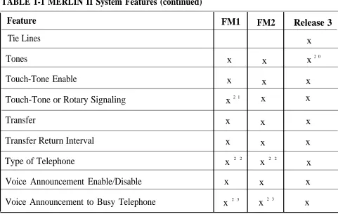
SYSTEM FEATURES Table 1-1 lists the features that are available for MERLIN II System Feature Modules 1 and 2, and Release 3.
NOTE: The features in Table 1-1 are described fully in
the MERLIN II Communications System System
Manual.
The following paragraphs describe feature that are either new in Release 3 or have been significantly modified for Release 3.
● Disallowed List. Using a Disallowed List, you can create up to eight lists of numbers, area codes, or exchanges that selected users will not be permitted to dial. Each list can have up to 10 numbers. The
administrator may assign one or more of these lists to any station in the system. If a station is assigned so a disallowed list any attempt to dial a number contained in the list wiIl be denied.
● Extended Station Status. Extended Station Status (ES Status) indicates the operating status of other stations to the administrator. When ES Status is administered for Hotel/Motel mode, the attendant can put voice terminals into different categories to indicate whether the room is occupied. With Release 3, if the voice terminal is off-hook, the attendant can’t change its status. This ES Status Inhibit feature helps prevent hotel guests from making calls from their room after they have checked out.
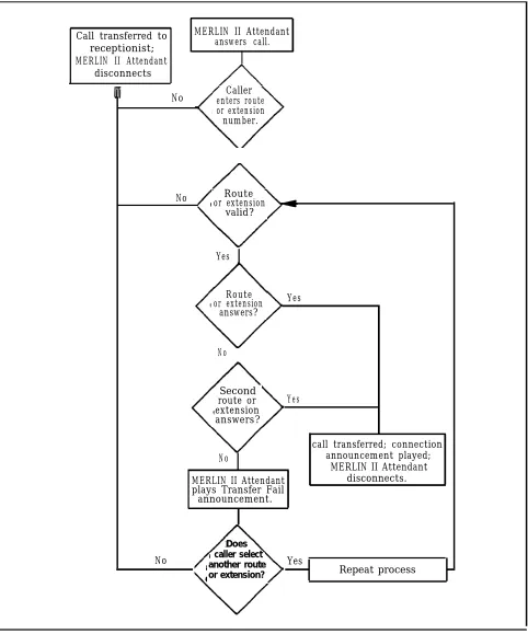
● MERLIN II Attendant. The MERLIN II Attendant automatically answers and routes incoming calls. The feature is available only when the optional MERLIN II Attendant accessory is installed. Also, to gain access to this feature, you must use the517C13 Basic
Telephone (012) Module.
The MERLIN II Attendant performs two major functions (Figure 1-3):
> Immediate call handling, in which all incoming calls are received and routed by the MERLIN II Attendant. Multiple MERLIN II Attendants can be used to handle call groups.
> Backup call handling, in which incoming calls are directed to the MERLIN II Attendant if the
receptionist (Station 10) does not answer within a predetermined number of rings.
Each of these functions includes night service call handling in which the MERLIN II Attendant maybe used for call coverage only after normal business hours.
● On-Line Module Swap. The On-Line Module Swap
feature allows you to replace a module in the control unit without powering the system down. The
replacement module must be the same as the one removed (i.e., a 408 module must be replaced with a 408 module). To use this feature, it is necessary to follow the exact procedures described in “On--Module Swap,w on page 4-7.
● Page All. This feature allows you to page all
telephones in the system at once over voice terminal speakers.
● Posted Message. The Posted Message feature provides a method of sending one of 20 user-defined messages to another terminal. Each message can be up to 16 characters long and will appear on the caller’s display.
● System Speed Dial. System Speed Dial allows the caller to store frequently used numbers as three-digit codes. For Release 3, the feature has been enhanced to accommodate 130 speed dial numbers.
Call transferred to receptionist; MERLIN II Attendant
disconnects
MERLIN II Attendant answers call.
▲ No Caller
enters route or extension number.
No Route or extension
valid?
Yes
Route or extension
answers?
Yes
No
Second route or extension answers?
Yes
No
call transferred; connection announcement played;
MERLIN II Attendant disconnects. MERLIN II Attendant
plays Transfer Fail announcement.
No
Does caller select another route or extension?
Yes
Repeat process
FIGURE 1-3 MERLIN II Attendant o p e r a t i o n .
TABLE 1-1 MERLIN II System Features
Feature FM1 FM2 Release 3
Account Code Entry x 1 x x
Allowed List x x x
Attendant (Automatic) [MERLIN II Attendant] x
Attendant Barge-in x x2
Attendant Position Setting x x x
Auto Answer All x x x
Auto Answer-Intercom x x x
Auto Intercom x x x
Automatic Line Selection (ALS) x x x
Automatic Route Selection (ARS) x x x
Basic Telephones x x x
Behind-Switch Operation x x
Bridging on Shared Lines x3
x3 x
Call Coverage x x x
1 The feature name is "Account Number Entry-
for Feautre Module 1. 2 The feature name is ‘Executive Barge-In-
TABLE 1-1 MERLIN II System Features (continued)
Feature FM1 FM2 Release 3
Call Forwarding and Follow Me x x
Call Park x x x
Call Pickup x4 x4 x4
Call Pickup Groups x x
Call Report (SMDR) x x x
Call Restriction x x x
Camp On x x
Centralized Programming x x x
Conference x x x
Coverage Inhibit x x x
Dialing Timeout Internal for Rotary Lines x x x
Direct Inward System Access (DISA) x x
Disallowed List x
Display x x x
Do Not Disturb x x x
Drop x x x
4 This feature in Feature Module 2 and Release 3 is the same as "Line Pickup” in Feature Module 1.
TABLE 1-1 MERLIN II System Features (continued)
Feature FM1 FM2 Release 3
Executive Barge-In x5 x
Extended Station Status (ES Status) x x
Flexible Numbering x x
Follow Me x x6
Forced Account Code Entry (FACE) x x
Group Call Distribution (GCD) x x x
Group Listening x x x 7
Group Page x x x
Hold x x x
Hold Disconnect Interval x x x
Intercom x x x
Intercom Dial Tone x x
Labels for Lines and Stations x8 x
Last Number Redial x x x
5 For Feature Module 2, the feature name is “Attendant Barge-In” and it operates only from an attendant station.
6 For Release 3, the feature name is “Call Forwarding and Follow Me”
7 The information for this feature is found in Section 2, "System Components," of the System Manual for Release 3.
TABLE 1-1 MERLIN II System Features (continued)
Feature FM1 FM2 Release 3
Leave Word Calling x x x
Line Assignments in Behind-Switch Systems x x
Line Assignments in Pooled Systems x9
x x
Line Assignments in Square Systems x 1 0 x x
Line Pickup x 1 1
Line Representation Setting x x 1 2
x 1 2
Line Request x x x
Loudspeaker Page x x x
Manual Signaling x x x
Menu Driven Administration x x 1 3
Message x x x
Monitor-on-Hold x x x 1 4
9 The feature name is "Line Pools" for Feature Module 1.
10 The feature name is "Square Line Configuration" for Feature Module 1. 11 This feature is called "Call Pickup" for Feature Module 2 and Release 3. 12 The feature name is “System Type” for Feature Module 2 and Release 3.
13 This is not technically a feature of MERLIN II System with Release 3, since menu-driven is the only administration method for that release. See “Overview” in Section 3, "Reference," of the Release 3 System Manual for information on menu-driven administration.
14 The information for this feature is found in Section 2, "System Components," of the System Manual for Release 3.
TABLE 1-1 MERLIN II System Features (continued)
Feature FM1 FM2 Release 3
Music-on-Hold x x x
Night Service x x x
Notify x x x
On-Hook Dialing x x x 1 5
On-Line Module Swap x
One-Touch Hold with Call Announcement x x x
Outside Auto Dial x x x
Page All x
PBX, Centrex, or Custom Calling Features x x
Personal Speed Dial x x x
Personalized Ringing x x x
Posted Message x
Privacy x x x
Reed x x x
Recall Timer Interval x x x
Reminder Service x x
TABLE 1-1 MERLIN II System Features (continued)
Feature FM1 FM2 Release 3
Ringing/Idle Line Preference x 1 6 x x
Ringing-on-Transfer x x x
Ringing Options x x x
Saved Number Redial x x x
Send Message x x x
Simultaneous Voice and Data Calls x x x
Special Characters in Programmed Dialing Sequences x x x
Stopwatch x x x
System Renumbering x x x
System Size x1 7
x x
System Speed Dial x x x
System Type x 1 8 x x
Test x x x1 9
16 The feature name is “Ringing Line Preference” for Feature Module 1. 17 The feature name is “System Size Setting- for Feature Module 1.
18 This feature name is "Line Represention Setting" for Feature Module 1.
19 The information for this feature is found in Section 2, "System Components," of the System Manual for Release 3.
TABLE 1-1 MERLIN II System Features (continued)
Feature FM1 FM2 Release 3
Tie Lines x
Tones x x x2 0
Touch-Tone Enable x x x
Touch-Tone or Rotary Signaling x 2 1 x x
Transfer x x x
Transfer Return Interval x x x
Type of Telephone x 2 2 x 2 2 x
Voice Announcement Enable/Disable x x x
Voice Announcement to Busy Telephone x 2 3 x 2 3 x
20 The information for this feature is found in Section 2, “System Components,” of the System Manual for Release 3.
21 The feature name is "Touch-Tone or Rotary Setting" for Feature Module 1.
22 The feature name is "Voice Terminal Type Setting" for Feature Module 1, and "Voice Terminal Type" for Feature Module 2.
System Hardware
The MERLIN II system includes the following hardware: MERLIN II SYSTEM
COMPONENTS
●
●
●
●
●
●
CONTROL UNIT COMPONENTS
Control unit
Voice terminals
> Analog
> Digital
Basic Touch-Tone
Digital data equipment
Modems
System accessories/auxiliary devices
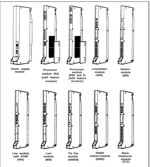
The assembly of modules containing a power source, a processor, and jack connections for outside lines, tie lines, MERLIN II system telephones, and other devices mounted on a carrier is called the control unit (Figure 1-4). The individual components are as follows:
● Basic carrier. The basic carrier is the main housing for the control unit. Every MERLIN II system must have at least one basic carrier, which houses the Power Supply Module, Processor Module, and up to five line and/or station modules.
● Expansion carrier. The expansion carrier provides slots for an additional Power Supply Module and six line and/or station modules. The expansion carrier does not require a Processor Module.
Basic carrier E x p a n s i o n carrier
FIGURE 1-4 Control unit components.
● Power Supply Module. The Power Supply Module receives an input of 117 VAC and supplies the system with the following dc voltages: +5, -5, and -48 VDC. The Power Supply Module can support up to 45 unit loads per carrier. (A unit load is a measure of power used to determine the electrical load of the MERLIN II system.) if the system’s power requirements exceed 45 unit loads, an Auxiliary Power Unit must be used. This device supplies an additional 20 unit loads to the
system. For more information on unit loads and the Auxiliary Power Unit refer to “Determining Unit Load Requirements” on page 2-57.
Processor module (R3) (with feature module) Power supply
module Processormodule (FM1 and 2) (with feature
m o d u l e )
Line module with DTMF
(400)
Line module
(800)
Tie line module (400EM)
Line/station module
(408)
Digital station-module
(008D)
Station module
(000)
Basic telephone
module (012)
FIGURE 1-4 Control unit components (continued).
● Processor Module. The Processor Module contains the circuitry that controls the system’s programs and features. It houses the Feature Module. Release 3 of the MERLIN II System must use Processor Module 517B7 with Feature Module 517F6.
● Feature Module. The Feature Module contains the Read Only Memory (ROM) and Random Access
Memory (RAM) for the system features. It is housed inside the Processor Module. The MERLIN II Release 3 Feature Module(517F6) must be used only with the 517B7 Processor Module.
● Line and station modules. Line and station modules provide jacks for the system’s tie lines, outside lines, and stations. Line and station modules can occupy slots 1 through 5 in the basic carrier and slots 6 through 11 in the expansion carrier. There is no required slot assignment for line and/or station
modules except that the module in slot 1 of the basic carrier must be a 408 or 008 module. Either of these modules provides the user with an analog station port (port 01) to administer the system.
> Analog line and station modules:
— 4-Line/8-Analog (408) Module. The 408
module is required for a MERLIN II system minimum configuration. It has four jacks for outside lines and eight jacks for analog
stations. The 408 module has a Power Failure Telephone (PFT) jack for connecting a Basic Touch-Tone or rotary telephone for backup during power outages. The system
automatically switches service to this jack in the event of a power failure.
>
>
>
– 8-Analog (008) Module. The 008 module has jacks for eight analog stations. It has no jacks for outside lines. Simultaneous voice and data is available but requires you to connect both an odd and even numbered jack to the same voice terminal.
– 4-Line (400) with DTMF Module. The 400 module has jacks for four outside lines and one PFT jack. The board has four Touch-Tone receivers.
– 8-Line (800) Module. The 800 module has jacks for eight outside lines and two PFT j a c k s .
E&M Tie Line (400 EM) Module. A tie line is a transmission facility dedicated to interconnect two private switching systems. The MERLIN II system Tie Line Module may be connected to another system locally or many miles away. Tie lines are provided by the telephone company.
Digital (008D) ModuIe. The 8-station digital module interfaces digital voice and data equipment to the system. Simultaneous Voice and Data is available on every port.
Basic Telephone (012) Module. The Basic Telephone Module permits Touch-Tone or rotary telephones to be used with the MERLIN II system. This module provides 12 station jacks and supplies the tip/ring interface and Touch-Tone circuitry needed for basic telephones. This module requires the installation of the Frequency Generator in the Power Supply Module.
The 517CI 3 Basic Telephone Module must be installed in order to use the MERLIN II Attendant.
Power indicator
Auxiliary power input jack
On/Off switch
P o w e r c o n n e c t o r
Ground lug
Label
Diagnostic 96-pin connector
SMDR port
Application port
Warning light
Power supply module Processor module (517B7) for Release 3
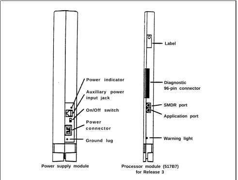
FIGURE 1-5 Module controls and indicators.
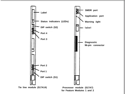
MODULE CONTROLS The from panel controls, indicators, and special
AND INDICATORS connectors (excluding line and station jacks) on control unit modules are described below. Refer to Figure 1-5 to locate these items.
Power Supply Module. The controls and indicators for this module are the following:
● Power indicator. Its light goes on when power is supplied to the module.
Label
Status indicators (LEDs)
DIP switch (S2)
Port 4
Port 3
Port 2
Port 1
DIP switch (S1)
SMDR port
Application port
Warning iight
l a b e l
Diagnostic 96-pin connector
Tie line module (517A14) Processor module (517A7) for Feature Moduies 1 and 2
FIGURE 1-5 Module controls and indicators (continued).
● On/off switch. This switch applies or removes power to the earner.
● Power connector. This is a male connector for the ac power cord.
● Ground lug. This connects the control unit chassis to an approved ground for the building.
VOICE TERMINALS
Processor Module. This module has the following port and light:
● SMDR port. This port is an interface to Station Message Detail Recording (SMDR) for call reports on call activity or a printout of system administration.
● Warning light. When this red light is lit it indicates that there is a problem with either the Feature Module, line or station module, or the Processor Module.
Tie Line Module. The controls and indicators for this module are the following:
● Status indicators (LEDs). The three status indicators show the condition of the Tie Line Module.
Green = test condition Amber = busy
Red = standby mode
● Dual In-Line Package (DIP) switch (S2). This switch controls the signaling format for tie line ports 3 and 4.
● DIP switch (S1). This switch controls the signaling format for tie line ports 1 and 2.
● Ports 4 through 1. These ports are jacks for tie lines.
Voice terminals are the user’s link to the MERLIN II system. They are designed to allow easy access to system features, and have various buttons and indicators to
facilitate operation The buttons on a voice terminal can function as line buttons or feature buttons. There are fixed feature buttons for the transfer, hold, recall, conference and drop features.
Voice terminals work like special input/output (I/O)
devices. The control unit performs all the decision making for the system while voice terminals act as the system’s sensors. Voice terminals inform the control unit of button depressions and feature status. They also inform the user of specific conditions by flashing lights or generating tones.
Voice terminals are connected to the control unit by a 4-pair wire. Each pair has a specific function:
●
●
●
●
Voice 1 pair. The control unit uses this pair of wires for the primary audio path to and from the voice
terminal. The control unit selects this pair to complete the path for outgoing, incoming, and intercom calls.
Control pair. The control unit receives information on voice terminal status and user input on this pair of wires. It also uses this path to send ringing and lighting instructions to the voice terminal.
Power pair. This pair provides power to the voice terminal.
Voice 2 pair. The control unit uses this pair of wires for the secondary audio path to and from the voice terminals. This pair is used with the analog voice terminal to provide the Voice Announcement to Busy Voice Terminal and the Simultaneous Voice and Data features.
Voice terminals used with the MERLIN II system are listed here. Refer to Figure 1-6 for examples of analog voice terminals, including the MERLIN II Display Console. Figure 1-7 shows digital voice terminals.
● Analog voice terminals
> > > > > . > > > > > > > > >
7102A
5-Button
10-Button
10-Button HFAI
10-Button with Built-In Speakerphone (BIS-10)
BIS-22
BIS-22 with Display
34-Button
34-Button Deluxe
34-Button (SP-34)
34-Button (SP-34D) BIS-34
BIS-34 with Display
Display Console (used to administer a system with Release 3)
NOTE: The new 7102A single-line voice terminal (not illustrated) has been certified for the MERLIN II system. It is the same as a basic telephone and must be connected to a 012 module.
● Digital voice terminals
> 7 4 0 6 D
> 7406D with Display
> 7406D with Data Stand
10-Button 10-Button
HFAI BIS-10
BIS-22D
with display 34-button
BIS-34 BIS-34D
with display
Display console
FIGURE 1-6 A selection of analog voice terminals.
7406D with display and Data Stand 7406D with
Data Stand
FIGURE 1-7 A selection of digital voice terminals.
BASIC OPERATION OF VOICE
TERMINALS
Voice terminals perform a variety of functions. With a voice terminal, a user can make and receive intercom and outside calls, page someone, and, with the proper voice terminal (the attendant console), administer the MERLIN II system. Buttons on voice terminals maybe
programmed for different functions. The following paragraph describe the basic operations of voice terminals.
● Administration. Two voice terminals, the Display Console and the BIS-34D, can be used to administer systems with Feature Module 1 and Feature Module 2. The Display Console, however, is the only voice
●
●
●
●
●
Dialing out or in. When a voice terminal goes off-hook, it signals the control unit to make a connection through a network switch to an available or requested outside line. When the path is established, the voice terminal receives a dial tone. The control unit will select a path in its multiplexing scheme to make the connection. A call coming into the will
activate the ring indicator in the control unit and generate control signals to alert the voice terminal.
Intercom call. Intercom calls can be made from one voice terminal to-any other voice terminal connected to the control unit. Dialing the intercom number of
another voice terminal will cause the control unit to establish a voice path between both voice terminals.
Loudspeaker paging. The system interfaces with auxiliary equipment such as a power amplifier and loudspeaker for single or multiple zone external paging.
Programming. In programming mode, instructions keyed into a voice terminal are stored in the control unit’s memory; the voice terminal itself has no
memory. When a particular feature is requested by a voice terminal, the control unit examines its memory to determine the features for that station.
For an analog voice terminal, you enter and exit programming mode by using the T/P switch. For a digital voice terminal, which doesn’t have a T/P switch, you must use a dial code to enter and exit programming mode. For a basic voice terminal, the administrator must program any feature changes.
Telephone paging. The MERLIN II system allows paging over voice terminal speakers. The Group Page feature allows paging to a maximum of 10 voice terminals. The Page All feature allows paging to all voice terminals in the system.
SYSTEM
ACCESSORIES
Figure 1-8 shows several of the MERLIN II system accessories described here.
● Alerter Accessories. Devices such as a horn, bell,
strobe, or chime can be connected to a Supplemental Alert Adapter so that people working in noisy or remote areas of a building can be alerted to incoming calls.
● Attendant Intercom Selector. Can be attached to a 34-Button Deluxe voice terminal when a MERLIN system has more than eight lines or more than 20 voice terminals. A system attendant can use the selector’s 30 buttons to access up to 120 Auto Intercom numbers. The light beside each button indicates whether a voice terminal or basic telephone is busy and whether a voice terminal’s message light is on.
● Auxiliary Power Unit. This unit must be added to the
control unit if the total number of voice terminals and voice terminal accessories (including Hands-Free Units and Headset Adapters) is greater than the control unit’s power capacity. The control unit supports up to 45 unit loads, and each Auxiliary Power Unit adds 20 unit loads to the system.
● Basic Telephone and Modem Interface. The BTMI connects telephones and data communications devices such as autodialers, answering machines, cordless telephones, facsimile machines, and modems to the MERLIN II system. A timer may be connected to a BTMI for automatic answering based on time of day.
Basic Telephone and Modem interface 2 (BTMI-2)
General Purpose Adapter (GPA)
Off-Premises Telephone Interface (OPTI)
Hands-Free Unit (HFU)
I n d o o r bell
Extra alert strobe
In-Range Out- of-Building Protectors (IROB)
Headset with Headset Adapter
Alerter accessories
Indoor horn
Indoor/outdoor alerter
FIGURE 1-8 A selection of MERLIN II system accessories.
● Basic Telephone and Modem Interface 2 (BTMI-2). The BTMI-2 is a replacement for the BTMI. It
connects telephones and data communications devices such as autodialers, answering machines, cordless telephones, facsimile machines, and modems to the MERLIN II system. A timer may be connected to a BTMI-2 for automatic answering based on time of day.
Unlike the BTMI, the BTMI-2 does not support
Conference, Drop, or line selection features. It can be used with MERLIN II systems with Feature Module 1, Feature Module 2, and Release 3.
● Basic Telephones. Basic Touch-Tone telephones, connected to the MERLIN system with the
Off-Premises Telephone Interface (OPTI) and to outside telephone lines, provide service to people at a remote location. On-premises Basic Touch-Tone telephones can be connected to the system with a Basic Telephone and Modem Interface 2 or a Basic Telephone Module.
● Frequency Generator. If your basic carrier or expansion carrier has a Basic Telephone (012)
Module, you must connect a Frequency Generator to the Power Supply Module, located in the first slot of each carrier containing Basic Telephone Modules.
The Frequency Generator converts 117-volt, 60-Hz input power to 105-vol~ 30-Hz ringing voltage for basic telephones connected to the Basic Telephone Module.
● General Purpose Adapter (GPA). Permits
connection of accessories such a modem with PCs or data terminals, cordless telephones, and autodialers to a MERLIN II system voice terminal. To use this
●
●
●
●
●
Hands-Free Unit (HFU). Provides the voice terminal user with full speakerphone capability. This includes hands-free telephone conversation, on-hook dialing, monitor-on-hold, and teleconferencing at a short distance from the voice terminal. To use this
accessory, you must program AUtO Answer- Intercom. The HFU is for use with all analog voice terminals except 5-button and 10-button HFAI. An HFU used with a 7406D voice terminal requires a local power unit.
Headset-and-Headset- Adapter. Enables a user to
answer and listen to calls without lifting the handset. The headset and headset adapter is for use with all analog voice terminals except 5-button and 10-button HFAI.
In-Range, Out-of-Building (IROB) Analog Voice Terminal Protectors. A voice terminal can be placed in another location outside of the main building but within 1000 feet of the MERLIN H system control unit. IROB protectors protect the control unit and voice terminal from exposure to lightning, contact with power lines, and power currents induced by nearby power lines.
Loudspeaker Paging System. An optional
loudspeaker paging system allows people with
MERLIN II system voice terminals to page co-workers and/or make announcements through loudspeakers.
Music Coupler. A music coupler connects a music source (such as a cassette player) to the MERLIN II system. It also provides a secondary bridged
connection to provide Music-on-Hold. In addition, it allows the music source to be connected to a
loudspeaker paging system to provide background music at the same time.
●
●
●
●
Off-Premises Range Extender (OPRE). The OPRE will be available in place of the Off-Premises Telephone Interface (OPTI) for users of Feature Module 1, Feature Module 2, and Release 3. The OPRE will allow users to connect off-premises Touch-Tone Basic telephones to the MERLIN II system.
NOTE: As of this printing the Off-Premises Range Extender is not available. Installation
information will be supplied in a CIB with the product.
Off-Premises Telephone Interface (OPTI).
Connects off-premises Touch-Tone Basic telephones to the MERLIN II system. Allows you to use an off-premises telephone to access many of the features of the on-premises communication system. The OPTI is used with MERLIN II Feature Module 1. It can also be used with Feature Module 2 and Release 3, but only for two-digit intercom numbers.
Power Failure Telephone. A power failure telephone allows calls to be made and received in case of a power failure. A Basic Touch-Tone or rotary telephone, when connected to a Power Failure
Telephone jack on a module in the control unit, bridges onto the lowest line number in the block of jacks that it serves on the module when a power outage occurs.
Theory of Operation
SYSTEM
ARCHITECTURE
The MERLIN II system architecture provides a digital network that supports voice and data communications. The modular nature of the system makes the base
configuration efficient and easy to expand. The control unit contains the memory for the system’s features, Input/Output (I/O) functions, and interface requirements. The various modules are electrically connected to a backplane assembly that provides common circuitry for the I/O bus, Time Division Multiplex (TDM) bus, and power distribution. Refer to Figure 1-9 for a fictional block diagram of MERLIN II system architecture. System architecture is made up of the following items: a
Processor Module interconnected to intelligent port modules by an I/O bus; a communications network made up of a TDM bus connected to the DigitaI Switch Element (DSE) of each module; and a Power Supply Module.
● Power Supply Module. The Power Supply Module converts 117 VAC line voltage to the following outputs: +5 VDC, -5 VDC, and -48 VDC (tip/ring).
● Processor Module. The central processor complex
consists of a main board and the Feature Module. The main board contains the 68000 microprocessor, RAM, a real-time clock, interrupt circuitry, and port interface to the modules through the I/O bus.
Communication between the Processor Module and the port processors on the various modules occurs over a parallel address/data bus. This structure allows
memory-mapped I/O with up to 1 megabyte per second bandwidth.
● Input/Output Bus. Included in the I/O bus are a
16-bit address bus and an 8-16-bit data bus. The address bus selects the module that receives instructions from the 68000 microprocessor. The microprocessor provides instructions to the port processors and Digital Switch Elements (DSEs) through the 8-bit data bus.
● Time Division Multiplex Bus. The Time Division
Multiplex bus (TDM) is a major part of the control unit. It connects the DSEs to allow voice and data to flow in and out of the MERLIN II system. The TDM bus is parallel, 8 bits wide, and runs at 2.048 MHz. Each TDM cycle has 256 time slots for voice, data, tones, and clocks.
Voice signals on the TDM bus are encoded in “Mu-Law 255” Pulse Code Modulation (PCM) format for domestic use and “A-Law 100” for international applications. See “Analog to Digital Signal
Processing” on page 1-40. Data signals are processed according to Digital Communications Protocol (DCP).
● 408 or 008 Module. A 408 Loop Start Line/ATL
Station Module or 008 module is required in slot 1 of the basic carrier of the control unit. Note, however, that the 008 module does not provide any outside lines
If you use a 008 module in this slot, you must provide for outside lines using another module.
The 408 module has a port processor to handle real-time intensive tasks such as ATL line protocol and central office rotary outpulsing. The port processor receives instructions from the main processor over the I/O bus. The instructions are stored in the dual port RAM. Buffer circuitry interfaces the I/O bus to the port processor.
The 408 module converts analog signals to digitaI for switching. Analog signals come into the 408 module through the outside lines and are converted to digital levels by coder-decodes (codecs). Voice and data signals going to the station jacks are converted to analog signals by codecs. Interface circuitry couples the analog output to the station jack. The DSE
interfaces voice and data with the TDM bus. The main processor (through the 1/0 bus) directs the DSE to place or remove samples from the TDM bus in specific time slots.
● 008D Module. The 008D Digital Module provides a digital interface to the system for PCs and other data devices. This module does not require codecs because no analog to digital conversion is required. Data flow through the module is controlled by the port processor, which receives its instructions from the I/O bus. Dual Line Interface (DLI) circuitry assures proper clocking and synchronization during all transfer cycles.
● 012 Module. The 012 Module interfaces basic
ANALOG TO DIGITAL SIGNAL
PROCESSING
Analog to Digital Signal Conversion
processor. The port processor directs Touch-Tone circuitry to output tones. The tones are placed on the TDM bus by the DSE through buffer circuitry. After a tip condition occurs at the remote end, a conversation may occur.
The MERLIN II system receives analog signals from the central office lines and analog modules. In order to be switched, the analog signals must be converted to digital signals. Digital transmissions have several advantages over analog transmissions. They produce superior bit error rates and have lower noise/signal degradation, simpler circuitry in some cases, and greater flexibility. They also have various performance advantages, such as speed and a nonblocking architecture.
If an analog signal is sampled in increments equivalent to twice the frequency of that signal, then the sample can faithfully reproduce the signal at a digital level.
The first step in analog to digital conversion is to sample the pulse amplitude of the analog signal. Then the sample is converted into a series of amplitude steps. This
technique is referred to as Pulse Amplitude Modulation (PAM). Analog to digital converters (codecs) are an integral part of voice and data systems. Codecs use a variety of encoding techniques. The MERLIN II system uses Pulse Code Modulation (PCM).
The process of converting an analog signal to a digital level increases the capacity and efficiency of data
transmissions. However, a digitized analog signal retains some of the problems of older transmission systems, such as having to be amplified.
Quantizing
Commanding
PCM uses PAM as its starting point but goes further.
PCM digitizes the information and sends the 8-bit code via PAM. PCM digitizes the PAM information by comparing each PAM sample to a point on a chart. Each point has a distinct 8-digit binary code. Therefore, it is the binary code, not the amplitude pulse, that is transmitted in PCM.
The process of converting PAM samples into discrete PCM values is known as “quantizing”. In the case of voice grade signals eight bits are commonly used to encode one PAM sample. Quantizing with eight bits allows 256
unique values to represent the analog signal being sampled. With adequate sampling of an analog voice signal, the digital product can be toll quality.
The quantizing process creates errors due in part to the “rounding off” of PAM samples into discrete PCM values. This distortion can be minimized by increasing the number of bits used to sample the analog signal or to increase the sampling rate.
Distortion also occurs in the quantizing process because equal consideration is given to all amplitude levels. Linear quantizing divides the amplitude range into equal
segments which results in unnecessary quality at levels where voice signals are unlikely to occur. Commanding eliminates this distortion by using a nonlinear scale which has smaller divisions and more accuracy in areas of the scale where voice signals are most likely to occur.
Commanding is, in effect, a compression/expansion of the quantizing scale. This nonlinear scale is more accurate in areas where signal amplitudes occur most (thereby
Mu-Law 255
A-Law 100
DIGITAL SWITCHING
Mu-Law 255 is a commanding scheme which uses a
compression ratio that is compatible with modern channel bank equipment. The scale is divided into 16 intervals, with each interval having 16 levels. Therefore, it has 256 discrete values. Mu-Law 255 has a negative and positive zero; therefore, it really has 255 discrete values. This commanding scheme is used in the United States and Japan.
The commanding scheme used in Europe is A-Law. It follows the same basic theory as Mu-Law 255 except that its scale is different. The scale tends to be more linear than Mu-Law 255. Because the intends tend to be equal, A-Law 100 does not concentrate its accuracy in areas of the scale where voice signals occur the most.
The Time Division Multiplex (TDM) bus allows many users to communicate over a common electrical
connection. The TDM bus is physically distributed across the backplane of the control unit and connects all
line/station modules. It is 8 bits wide and has a frequency of 2.048 MHz. The frame repetition rate is 8 KHz
providing a 64 Kbps channel on each of the 256 time slots. The TDM bus has specific time slots for various functions.
During a conversation between station A and station B, a time slot is reserved for station A to transmit on and
another for station B to receive on. Because the TDM bus cycles 8 thousand times per second, the conversation is continuous. The TDM bus carries tones and control signals to stations. Unlike other bus configurations, the stations on the TDM bus receive all transmissions. If a station is not assigned to any of the time slots, the TDM bus will ignore the data. Refer to Figure 1-10 for an example of the TDM bus.
The Digital Switch Element (DSE) functions as a digital switch for voice and data. It also performs the operations for commanding schemes such as A-Law and Mu-Law.
Each module has a DSE to interface codecs or digital transceivers to the TDM bus. The actual digital switching occurs when the DSE is programmed by the system I/O bus to place (transmit) data or retrieve (receive) data on the TDM bus in specific time slots. This process also involves time slot interchanging so that an available slot in the TDM cycle can be filled with a talk (transmit) or listen (receive) slot. The DSE provides dynamic conferencing ability by allowing up to 16 time slots to be conference together and sent out to a single port (station).
408 Module
CODEC 008D Module
D / A converter DSE i n t e r f a c e DSE Interface circuity
A / D converter
Analog voice terminal
TDM Bus
256 Time slots in one TDM cycle
0 1 2 3
…
60 61 62 63…
150 … 160…
200 … 220 … 225 TimeTime slots for control signals. Time slots for tones. Analog station talks on time slot 150 and listens on time slot 160. The conversation is continuous.
Digital station sends data on time slot 200 and receives data on time slot 220.
SYSTEM CAPACITY The MERLIN II system hardware limits the system capacity for the items found in Table 1-2.
TABLE 1-2 MERLIN II System Capacity
Item Capacity
Module slots 17
Board signatures 16
Time slots - 256
Simultaneous duplex connections 108
Tones 40
Table 1-3 lists items that the system architecture either allows or requires.
TABLE 1-3 Port Requirements for Features and System Accessories
Feature
Music-on-Hold interface
External paging interface
Analog Simultaneous Voice/Data
Analog Voice Announcement to Busy Voice Terminal
Digital Simultaneous Voice/Data
Extra alert devices (with SAA)
Port Requirements
1 CO line (administered)
1 CO line (administered)
2 ATL station ports
2 ATL station ports
1 DCP station port
1 ATL station port
E&M SIGNALING Most signaling systems, other than loop signaling, are separate from the trunk equipment. They are normally located between the trunk equipment and the line facility. E&M signaling systems derive their name from the
historical designations of the signaling leads on
schematics covering these systems. By convention, the "E" stands for ear and the "M" stands for mouth (rEceive and transMit). The E&M lead signaling interface consists of two leads between the switching equipment (central office) and the signaling equipment (PBX). The “M lead carries signals from the switching equipment to the
signaling equipment. The “E” lead carries return signals from the signaling equipment to the switching equipment. The E&M interface is designated as TL31M, and the 50-pin connector is designated as RJ2GX. At the RJ2GX interface, the PBX is the switching equipment side, and the network side (toward the central office) is the
MERLIN II System T R T 1 R1 M E Central office RJ2GX T1 R1 T R E M Off-hook
Site #1 dials number for site #2
E lead
On-hook
RJ2GX Centraloffice
SITE #l Dial tone M lead E lead M lead SITE #2
M lead of site #1 connected to E lead of site #2
M lead of site #2 connected to E lead of site #1
Conversation Disconnect Disconnect E lead Ring M lead M lead E lead Dimension PBX Off-hook On-hook
FIGURE 1-11 E&M signaling.
E&M Tie Line Parameters
The MERLIN II system 400EM Tie Line Module has four line ports. Each must be administered individually. All tie line options are software administered except for the
signaling format parameters (signaling mode and signaling type). These are selected by DIP switches on the Tie Line Module. The following is an explanation of tie line
options. For more information, see “Administering Tie Lines” on page 3-50 in Section 3, “Administration”.
Direction A tie line may be administered in one of the three following ways:
● Two-way (default): Calls may be made in either direction.
● Outgoing only: Calls may be made but not received.
● Incoming only: Calls may be received but not made.
Type There are four types of tie line options.
●
●
●
●
Wink start (default): The originating end of the tie line transmits an off-hook signal and waits for the remote end to send a signal indicating that it is ready (a wink). This is also know as a dial repeating tie line.
Automatic start: Incoming calls are routed directly to
an attendant station without a start signal. This is also known as an automatic ringdown tie line.
Immediate start: No start dial signal is necessary. Dialing may begin immediately following seizure of a line. This is also known as a dial repeating tie line. Delay dial start: The originating end of the tie line transmits an off-hook signal and waits for the remote end to send a delay dial signal (an off- hook signal followed by an on-hook signal). This is also known as
a dial repeating tie line.
Signaling Mode Signaling mode designates the
electrical interface used.
● E&M mode: The signaling leads are isolated from the transmission leads. The E&M mode can be either protected or unprotected.
● Unprotected mode: Must be used for the E&M
Type 1 Standard interface in order to meet voltage drop criteria for the interface. This mode is used when there is a network interface.
● Protected mode: Resistance is added in tie M lead to provide additional protection from foreign
voltages and transients. This mode is used on local tie lines, such as between systems in different
buildings.
● Simplex mode: The signaling leads are superimposed onto the analog transmission leads to provide a two-pair interface. Resistance is included in the signaling leads for protection from foreign voltages and
transients. This mode is used primarily with E&M Type 5 signaling on local tie lines.
Signaling Type Signaling type designates the logical
signaling used. There are the following three options:
● Type 1 Standard (default): The M leads are used for signaling from PBX to line. Off-hook is -48 VDC and on-hook is local ground. Signaling in the other
direction uses local ground for off-hook and open for on-hook.
● Type 1 Compatible: This interface is back-to-back compatible with Type 1 Standard. It allows direct connection between systems where no intermediate signaling equipment is used.
● Type 5: A symmetrical 2-wire arrangement that signals in both directions by means of open for on-hook and ground for off-hook. The primary application of Type-5 interface is local tie lincs.
Dialing Mode This option sets the dialing mode for the tie line.
● Touch-Tone
● Rotary (default)
Dial Tone This option determines whether the dial tone
originates from the remote or local end of the tie line, or both (you receive a second dial tone).
● Remote (default) ● Local
Answer Supervision Time This option sets a time limit
in milliseconds (ms) for the remote station to signal the calling station.
● 20 to 4800 ms (increments of 20 ms)
● 300 ms (default)
Tie Line Disconnect Time This option sets a time limit
for the release of the E or M lead.
● 140 to 2400 ms (increments of 10 ms)
● 300 ms (default)
Your choice of signaling format (signaling mode and type) depends on the particular application. Using Table 1-4 “Tie Line Preferred Signaling Formats,” you can
TABLE 1-4 Tie Line Preferred Signaling Formats
Installation Situation Preferred Signaling Format From
MERLIN II System MERLIN II System Far End
Signaling Protected Signaling Protected
Mode and or Mode and or
To Location Type Unprotected Type Unprotected
MERLIN II Same Site Simplex N/A Simplex N/A
System or Inter- Type 5 Type 5
building
System 25 Same Site Simplex N/A Simplex N/A
System 75 or Inter- Type 5 Type 5
building
System 85 Same Site Simplex N/A Simplex N/A
or Inter- Type 5 Type 5
building
Dimension Same Site E&M Unprotected E&M Unprotected
PBX Type 1 Type 1
Compatible Standard
Dimension Inter- E&M Protected E&M Protected
PBX building Type 1 Type 1
Compatible standard
Other Same Site E&M Unprotected E&M Unprotected
Type 1 Type 1
Compatible Standard
TABLE 1-4 Tie Line Preferred Signaling Formats (continued)
Insulation Situation Preferred Signaling Format
From
MERLIN II System MERLIN II System Far End
Signaling Protected Signaling Protected
Mode and or Mode and or
To Location Type Unprotected Type Unprotected
Other Inter- E&M Protected E&M Requires a
building Type 1 Type 1 protection
Compatible Standard unit
Network … E&M Unprotected Either Either
interface Type 1
System Connectivity
This section describes typical hardware configurations for a MERLIN II system with accessories and auxiliary
equipment Connectivity diagrams with descriptions are provided for the following:
●
●
●
●
●
●
●
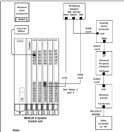
Simultaneous voice and data (analog station) using the analog station module (408) to gain access to a remote host computer.
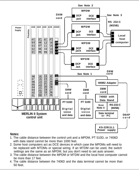
Simultaneous voice and data (digital station) and local host computer access using the digital station module (008D).
Modem pool using the digital station module (008D) and the basic telephone module (012).
Modem pool using the digital station module (008D) and the analog station module (408).
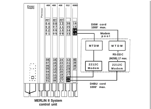
Modem pool on dedocated outside lines for
data-Background music provided for callers through Music-on-Hold.
External loudspeaker paging.
SIMULTANEOUS VOICE AND DATA
Simultaneous voice and data at an analog station allows the user to connect to the system an analog voice terminal and a data terminal or PC with data rates set by the
modem. This feature requires both an odd and even jack to be connected to the voice terminal. Refer to the
connectivity diagram in Figure 1-12.
Simultaneous voice and data at a digital station allows the user to have a digital voice terminal and a data terminal or PC with data rates up to 19,200 bps between digital
endpoints. Note that between the Modular Trunk Data Module (MTDM) and the modem there can be a maximum of 17 feet. Refer to the connectivity diagram, especially Note 2, in Figure 1-13.
R e m o t e host c o m p u t e r
Modem
C e n t r a l Office
P o w e r
S u p p l y 4 0 8 4 0 8 4 0 8 4 0 8 4 0 8
04 PFT 03 02 01 PFT 08 07 06 05 PFT 12 11 10 09 PFT 16 15 14 13 PFT 20 19 18 17 Bridging adapter BR 241-B1 Even Station Odd
■ ■ ■
Analog voice D 8 W terminal cord
■ Line
Other
■
D 8 A C cord
■
VT General Purpose A d a p t e r
Tel Equip
D 8 W ■
cord cord
D 4 B U cord
■
See Notes 1 Line and 2
M o d e m 2 2 1 2 C
T e r m i n a l
■ 08 07 06 05 04 03 02 01 16 15 14 13 12 11 10 09 24 23 22 21 20 19 18 17 32 31 30 29 28 27 26 25 40 39 38 37 36 35 3 4 3 3 RS-232-C (M25B)
MERLIN II System
Control unit Data
terminal or PC
Notes:
1. Bridging adapter connects adjacent odd/even jacks (23, 24) to analog voice terminal. This type of connection is required for features such as Voice Announcement to Busy Telephone or Simultaneous Voice and Data.
2. Total distance between the control unit and the voice terminal cannot be more than 1000 feet without local power.
LOCAL HOST Local host computer access allows shared use of the host COMPUTER ACCESS computer through Modular Processor Data Modules
(MPDMs). The MPDMs may have different data rates or the same rate, each set to a data rate of 19,200 bps or less. Refer to the connectivity diagram in Figure 1-13.
MODEM POOLS Modem pools are groups of modems and associated
equipment used to convert digital data signals to analog data signals or vice versa. Putting modems in pools makes it easier for users to share a limited number of modems. Each modem pool is used exclusively for either incoming or outgoing calls.
Connected to Basic The modem pool members use available basic telephone Telephone Jack jacks to send data between digital endpoints and remote
computers over MERLIN II system lines. Refer to the connectivity diagram in Figure 1-14.
Connected to Analog The modern pool members use available analog station Station Jacks jacks to send data between digital endpoints and remote
computers over MERLIN II system lines. Refer to the connectivity diagram in Figure 1-15.
Connected to Dedicated Outside Lines
The modem pool members use dedicated outside lines to send data betwecn digital endpoints and remote
computers. This type of modem pool would likely be used if thcrc were many data calls to remote computers in order to save the MERLIN II system lines for voice use. Refer to the connectivity diagram in Figure 1-16.
See Note 2
MPDM D 8 W DCP
DCE See Note 3 cord ■ jack interface■
RS 232-C
4 0 8 4 0 8 4 0 8 4 0 8 0 0 8 D M P D M (M25B)
Power Supply
DCP DCE ■
■ jack interface PFT 08 07 06 05 20 19 18 17 ■ ■ ■ ■ PFT 04 03 02 01 PFT 12 11 10 09 PFT 16 15 14 13 Local host computer M P D M
■ DCP
jack interfaceDCE ■
M P D M DCP DCE
■
Jack interface■
D 8 W See Note 1 cord 08 07 06 05 04 03 02 01 16 15 14 13 12 11 10 09 24 23 22 21 20 19 18 17 32 31 30 29 28 27 26 25 36 35 34
33 400B2 Adapter
D8W
D8W D8W
cord cord cord 7406D with
Data Stand PT 510D PT 510D
S e e Note 4
RS-232-C (M25B) D i g i t a l
voice and data
D i g i t a l v o i c e and data
MERLIN II System control unit
Data terminal
o r P C D6AP c o r d
KS-22911L1 Power supply
Notes:
1. The cable distance between the control unit and a MPDM, PT 510D, or 7406D with data stand cannot be more than 1000 feet.
2. Some host computers act as DCE devices in which case the MPDMs will need to be replaced with MTDMs or special wiring. If an MTDM can be used, the switch settings are the same as an MPDM, but you don't need to set auto answer.
3. The cable distance between the MPDM or MTDM and the local host computer cannot be more than 17 feet.
4. The cable distance between the 7406D and the data terminal cannot be more than 50 feet.
Power Supply
408 408 408 012 008D
PFT 0 4 0 3 0 2 0 1 PFT 0 8 0 7 0 6 0 5 PFT 1 2 1 1 1 0 0 9 3 6 3 5 3 4 3 3 1 6 1 5 1 4 1 3 D8W cord 1000' max. Modem p o o l
08 07 06 05 04 03 02 01 16 15 14 13 12 11 10 09 24 23 22 21 20 19 18 17 3 2 3 1 3 0 2 9 2 8 2 7 2 6 2 5 40 39 38 37 D4BU cord
MERLIN II System control unit
-M T D -M M T D M
RS-232-C (M25B) 17 max.
2 2 1 2 C 2 2 1 2 C M o d e m M o d e m
-1000' max.
FIGURE 1-14 Connectivity of a modem pool using a basic telephone module.
P o w e r
Supply 4 0 8 4 0 8 4 0 8 4 0 8 0 0 8 D
PFT 04 03 02 01 PFT 08 07 06 05 PFT 1 2 1 1 1 0 0 9 PFT 16 15 14 13 20 19 18 17 D8W cord Modem pool
-M T D -M M T D M RS-232-C (M25B)
17' max. 2 2 1 2 C
M o d e m
2 2 1 2 C M o d e m D4BU cord 08 07 06 05 04 03 02 01 16 15 14 13 12 11 10 09 24 23 22 21 20 19 18 17 3 2 3 1 3 0 2 9 2 8 2 7 2 6 2 5 36 35 34 33
B a s i c Telephone and Modem
Interface 2
B a s i c Telephone and Modem Interface 2 -D8W cord 1000’ max.
MERLIN II System control unit
Power Supply
4 0 8 4 0 8 4 0 8 4 0 8 0 0 8 D
PFT 04 03 02 01 PFT 0 8 0 7 0 6 0 5 PFT 1 2 1 1 1 0 0 9 PFT 1 6 1 5 1 4 1 3 2 0 1 9 1 8 1 7 RS-232-C (M25B) 17’ max. - - - -
/
D8W cord 1000' max./
M T D M 2 2 1 2 C Modem 08 07 06 05 04 03 02 01 1 6 1 5 1 4 1 3 1 2 1 1 1 0 0 9 2 4 2 3 2 2 2 1 2 0 1 9 1 8 1 7 32 31 30 29 28 27 26 25 36 35 34
33 M T D M
2 2 1 2 C Modem -Modem pool D4BU to Central Office line jack
MERLIN II System control unit
FIGURE 1-16 Connectivity of a modern pool on dedicated outside lines.
GENERAL Modems are an essential part of MERLIN II system
REQUIREMENTS FOR features involving local and remote computer access. Any
MODEMS modem other than the 2212C used with system hardware
should meet the following requirements to ensure proper operation under all conditions. Modem requirements differ according to applications. When planning the system, remember the various modem configurations such as a single modem for analog voice/data or modem pools. The planning information recorded on the individual Station Configuration forms should reflect the exact modem arrangement for each station.
Basic Requirements for Modems
●
●
●
●
●
●
●
●
●
Requirements for Outgoing Modem Pools
The following paragraphs describe the basic requirements for any modem, and specific requirements when used in outgoing and incoming modem pools.
NOTE: Modems can meet these requirements through
fixed features or through hardware and software options that can be set. An option setting may make a modem appropriate for one pool in the MERLIN II system but not another.
The basic-requirements for modems are the following:
Full-duplex operation, for switched networks
A single speed between 300 bps and 19,200 bps
Serial transmission of characters in a binary asynchronous format
EIA RS-232-C interface
Peak signal level compatible with the MERLIN II system
Modular jack connection for telephone network
Loss of earner disconnect so that the modem goes on-hook and turns received line signal detector, EIA lead RLS (carrier on) off
Disconnect if EIA lead DTR (data terminal ready) goes off
Passing of break character and long space signal
Saving of options during power outage
In addition to meeting the basic requirements, a modem used for outgoing calls must have the following