Study the Effect of Wind Load and Dead Load on RC Hyperbolic
Cooling Tower by the Provision of Stiffeners
Mariya Jacob1, Aswathi Mohanan2
1
Civil Department, KTU University, Thiruvanathapuram, Kerala, India
2
Asst. Professor, Civil Department, KTU University, Thiruvanathapuram, Kerala, India
Abstract
Reinforced concrete hyperbolic cooling tower is an important part in thermal and nuclear power plants. The taller high thicker tower subjected to self weight and dynamic loads. This paper deals with effect of wind load as well as dead load on the structures by providing different types of cross section of stiffeners and there by increase the stability and decrease the stress concentration on the structures. For the purpose of study finite element method is carried out by wind analysis on ANSYS software. The adding stiffeners which helps to reduce the shell thickness from 200mm to 160mm and minimize the dead weight also. Based on the analysis, types of stiffeners, optimized dimensions and material used for the stiffeners are defined and methodology is discussed.
Keywords: R.C hyperbolic cooling tower, FEM, Wind analysis, Types of cross section of stiffeners
1. Introduction
Hyperbolic cooling tower are the one large type of shell structures used for cooling of water in thermal and nuclear power stations. The main process involves is, evaporation of water to reject heat to atmosphere and cooling of working fluid. Due to its large space availability at the bottom and accelerating convective air flow in upward direction, hyperbolic shape is to be most preferable for the geometry of the tower. These structures subjected to both self weight and environmental forces like earthquake force and wind force. The high taller and thick shell of the structure contributing high dead loads on the structures. Therefore dead load and wind load considered as the major load for analysis and design of the structures. In this study minimize the dead load by reducing the shell thickness and provides stiffeners.
Research works about cooling tower have been reported with review of literature survey. sachin kullkarny [1], this paper deals with static and dynamic analysis of hyperbolic cooling tower. Seismic and wind analysis carried out for 2
existing tower and obtain optimal height with low concentration of stresses. A.M.EI. Ansary [2], in this study he developed a numerical tool that is capable of achieving an optimal shape and design of tower by coupling of non-linear FEA modal. Prashanth N [3], studied effect of seismic and wind loads on hyperbolic cooling tower of varying dimension and RC shell thickness with respect to reference tower. Y.Tamura [4],this paper describes about a new approach for analyzing wind induced responses and corresponding equivalent static wind load by a consistent coupling method and an aero elastic model was developed. Xin Jia [[5],investigated failure mode of RC hyperbolic cooling tower ,consider changes of material and geometric properties .Result is that, tower would still fail by loss of strength ,characterized by the existence of an ultimate load and of yielding of the reinforcement.
2. Objectives
a) To find out the influence of wind loads on RC
hyperbolic cooling tower by the provision of stiffeners using finite element software
b) To compare the results of an existing hyperbolic
cooling tower and hyperbolic cooling tower with stiffener by wind analysis.
c) To optimize size of cross section of stiffener with
minimum stress and deformation condition
3. Description of Geometry of Tower
and top end is free. The detail information shown in figure1.
Fig. 1 Geometry of the hyperbolic cooling tower
The material properties of RC tower is consider as, unit
weight of concrete 24 kN/m3, Poisson’s ratio of 0.15 and
Young modulus of 31GPa respectively.
4. Forces Consider For Analysis
4.1 self-weight
Self- weight, of hyperbolic cooling tower is determined by multiply unit weight of concrete with surface area and shell thickness. In the case of ANSYS 16.2 workbench, self – weight is assigned by applying gravity load.
4.2 Wind Load
The wind pressure at a given height [Pz] will be computed as per IS: 875 (part 3)-1987. For computation of design wind pressure, the basic wind speed (Vb) will be taken as Vb=39 m/s at 9.2m height above mean ground level. Then design wind speed (Vz) is computed at a height z, the risk coefficient K1=1.06 will be considered and coefficient K2 terrain category 2 as per table 2 of IS: 875 (part-3)-1987. Coefficient K3 taken as 1 for the tower under consideration. The wind pressure at a given height determined by using the equation as per code.
Pz = 0.6 Vz2 N/m2 (1)
Vz =Vb x K1 x K2 x K3 (2)
5. Description of finite element model
Finite element analysis is adopted because of the complexity of the material properties, the boundary conditions and the tower structure. The finite element analysis of the cooling towers has been carried out using ANSYS workbench 16.2. In this study, shell portion of the cooling towers has been modeled and assuming bottom end is fixed condition
5.1 Geometric model of cooling tower by FEA
The hyperbolic cooling tower is modeled by sketching the curved portion by arc command in a given height and attaching base portion by line command. This 2 dimensional figure is then changed in to 3 dimensional one by using revolve option by 360 degree.
Fig .2 Finite element model of cooling tower
5.2 Meshing and Loads Application
Fig .3 Meshing of cooling tower
Only self-weight and wind load is considered for loading condition of the cooling tower. Self-weight calculated by assigning gravity load. This is automatically generating the software. For wind load calculation IS: 875 (part-3)-1987 is referred.
Fig .4 Loads on cooling tower
5.3 Finite Element Analysis
Wind analysis is carried out for this study. First we creating the Geometry of the model in ANSYS by using arc and line command & we have to input material
properties and make mesh by quadrilateral method to
model in Pre processor. Then assigning the loads & boundary conditions and input the Pressures alongside to the model as wind pressure. Finally solve the problem in solution & read the results in General post processor
.
6. Optimization
Based on the researchers found that, construction of the stiffeners increases the buckling safety factor and structural stability. The self weight due to high thicker of shell which affects the Structural stable condition. So in order to reduce and slender the shell thickness, stiffener is provided on the tower.
The arrangement of stiffener is important for stability and economic condition. So that stiffeners is provided by reducing shell thickness from 200mm to 180mm. For that 4 vertical stiffeners and 4 horizontal stiffeners provided with equal distance of spacing which gives the better results. Mainly two different types of materials are used for stiffeners. Steel and concrete stiffeners. Steel is more economic than concrete. In case of steel stiffener, five different types of cross section of stiffener taken. Channel, T-section, rectangular hollow section, I-section, and circular hollow section .In concrete, square and circular section of stiffener consider.
Fig .5 Von-mises stresses on channel section
Fig .6 Total deformation on channel section
Channel section of size 370x80x11x19 mm gives the optimized section compared to other types of steel stiffener.
Fig .7 Total deformations on square section
Square stiffener of size 480x480 mm concrete stiffener gives least value of deformation and von-misses stresses compared to circular section.
Fig .8 Von-misses stresses on square section
Based on this results additional rings are applied by reduce the shell thickness into 160mm for channel and square section. Addition of 2 horizontal stiffener rings provides gives results of slight reduction in deflection and stresses
Table 1: Optimum size of steel stiffeners
Cross sections
Optimized size (mm)
Total deformat ion (mm)
Von-mises stresses
(MPa)
Channel 370x80x11x19 25.162 4.8453
T- section 330x170x10x15 25.162 4.8459
Rectangular tube
640x240x16 25.234 4.8547
I-section 290x270x15x20 25.287 4.8326
Circular hollow section
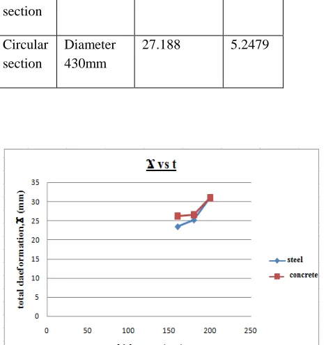
Table 2: Optimum size of concrete stiffeners
Fig .9 Total deformations by steel and concrete stiffeners
Fig .10 Von-mises stresses by steel and concrete stiffeners
7. Conclusions
In this project, effect of wind load and self-weight of hyperbolic cooling tower by the provision of various types of stiffeners is studied by reducing shell thickness.
1. On comparing cooling towers with and without
stiffeners in wind analysis, provision of stiffeners on cooling towers gives least value of deformation and von-misses stresses for varying shell thickness
2. Among 5 types of steel stiffeners of different cross sections, channel section of size 370x80x11x19 mm is the optimized section and in 2 types of concrete stiffeners, square section of size is 430x430 mm shows better results compared circular stiffener
3. Additional stiffener provision gives only slight reduction in deflection and stresses & also an un economic condition for extra steel stiffeners.
8. References
[1] Sachin kulkarni, Prof A.V.Kulkarni, “Static and Dynamic Analysis of Hyperbolic Cooling Tower”, Journal of Civil Engineering Technology and Research, ( 2014), Volume 2,
Number 1 pages 39-61
[2] A. M. El Ansary, A. A. El Damatty, and A. O. Nassef, “Optimum Shape and Design of Cooling Towers”, World Academy of Science Engineering and Technology International Journal of Civil Environmental, (2011), Volume: 5, No: 12
[3] Prashanth N, “To study the effect of seismic and wind loads On Hyperbolic cooling tower of varying dimension and RCC Shell thickness”, The International Journal of Science & Technoledge, (2013), Volume 1 Issue 3 September [4]Y.Tamura, “A new methodology for analysis of
Equivalent static wind loads on super-large cooling towers”, Journal of Wind Engineering and Industrial Aerodynamics (2013)Volume 111, pages 30-39
[5] Xin Jia, “Revisiting the failure mode of a RC hyperbolic Cooling tower, consider changes of material and geometric Properties”, Journal of Engineering Structures (2014), Volume 47, pages 148-154
Cross sections
Optimized size
(mm)
Total deformation
(mm)
Von-mises stresses
(MPa)
Square section
430x430 26.661 4.92
Circular section
Diameter 430mm