R E S E A R C H
Open Access
A synchronization technique for generalized
frequency division multiplexing
Ivan S Gaspar
1*, Luciano L Mendes
2, Nicola Michailow
1and Gerhard Fettweis
1Abstract
Generalized frequency division multiplexing (GFDM) is a block filtered multicarrier modulation scheme recently proposed for future wireless communication systems. It generalizes the concept of orthogonal frequency division multiplexing (OFDM), featuring multiple circularly pulse-shaped subsymbols per subcarrier. This paper presents an algorithm for GFDM synchronization and investigates the use of a preamble that consists of two identical parts combined with a windowing process in order to satisfy low out of band radiation requirements. The performance of time and frequency estimation, with and without windowing, is evaluated in terms of the statistical properties of residual offsets and the impact on symbol error rate over frequency-selective channels. A flexible metric that quantifies the penalty of misalignments is derived. The results show that this approach performs practically as state-of-the-art OFDM schemes known in the literature, while it additionally can reduce the sidelobes of the spectrum emission.
Keywords: GFDM; Synchronization; Windowing; Metric
1 Introduction
Many of today’s digital communication systems use orthogonal frequency division multiplexing (OFDM) [1] as physical layer interface, mainly because of its robust-ness against frequency-selective channels and easy means of implementation. However, OFDM has some important drawbacks that make it questionable for future wireless systems as 5G networks [2]. In particular, the high out-of-band (OOB) emissions [3] of OFDM signals are an obstacle when using this technology in fragmented spec-trum and dynamic specspec-trum allocation scenarios. Clearly, OFDM is not a straightforward choice for 5G networks, and consequently, new waveforms are being investigated for next-generation standards. However, it is highly con-venient if the techniques developed for OFDM can be somehow be applied for new waveforms.
Normally, synchronization techniques for OFDM neglect the effects of the OOB in the preamble design. However, this is an important aspect to be addressed with generalized frequency division multiplexing (GFDM) [4]. Therefore, the main contribution in this paper is the
*Correspondence: [email protected]
1Technische Universität Dresden, Georg-Schumann-Str. 11, Dresden D-01187, Germany
Full list of author information is available at the end of the article
investigation of a solution for the GFDM synchroniza-tion that does not increase the OOB emission and has a performance equivalent to the solutions designed for OFDM.
GFDM is a flexible solution to address the requirements imposed by the new scenarios foreseen for the 5G net-works [2]. In this scheme, a symbol composed of several subcarriers and multiple subsymbols is used to transmit a data block, where each subcarrier is pulse-shaped with a transmission filter. In order to avoid spending addi-tional samples on ramp up and ramp down of the filter response, the impulse response for each subsymbol is applied through circular convolution. This approach is also called tail biting [4]. Different pulse shapes can be used as prototype filters, which introduce a new degree of freedom to the system. The subcarrier filtering not only reduces OOB emissions but also might introduce intercarrier interference (ICI) and intersymbol interfer-ence (ISI). However, receiving techniques such as zero forcing [5] or a matched filter in combination with suc-cessive interference cancellation (SIC) [6] can reduce the impact of the self-generated interference and lead to an error rate performance equivalent to OFDM. Imple-mentation approaches based on fast Fourier transform (FFT) algorithm show that it is possible to efficiently
construct GFDM transceivers with the technology avail-able today [7].
One of the main challenges in the multicarrier receive chain is symbol time offset (STO) [8] and carrier fre-quency offset (CFO) estimation [8]. Among the syn-chronization approaches available for OFDM, data-aided methods allow the use of both autocorrelation and cross-correlation properties, and one-shot synchronization can be achieved in bit pipe and burst communications. A sequence composed of two repeated OFDM symbols was first proposed in [9] in order to explore a strong autocor-relation property for CFO estimation, and shortened data symbols were suggested to address wider CFO estimation range. This idea is addressed by [10] with the construction of a single OFDM symbol constituted with two repeated parts. A coarse STO can be achieved with this proposal as well, but the use of cyclic prefix (CP) and cyclic suffix (CS) creates a plateau effect in the autocorrelation, which introduces ambiguity and reduces the precision of the technique. In [11], a solution using additional integration, i.e., moving average along the CP and CS length, to remove plateau effects is proposed. Nevertheless, the metric has a pyramidal shape, which leads to STO estimation errors in noisy environments. These methods are explored in the algorithm in [12] to obtain a robust CFO estimation, and after correcting the CFO, the integrated autocorrelation method is combined with a cross-correlation, leading to an optimized impulsive time metric. An additional thresh-old criterion allows the fine estimation of the time offset of the first tap of a multipath channel, based on the statistical properties of the previous samples and a given probability of false alarm [13].
In contrast to the large number of synchronization tech-niques that are available for OFDM, there is a lack of solutions for GFDM. All mentioned techniques consider a rectangular pulse shape, which produces non-negligible OOB emissions and low decaying spectrum sidelobes. This paper presents an approach for data-aided synchro-nization scheme for GFDM pinching of block boundary of the preamble with a window function to provide smooth fade-in and fade-out transitions. As additional contri-bution, this paper also presents a metric that evaluates the effect of residual offset errors in the GFDM symbol. This metric allows quantifying the equivalent signal-to-noise ratio (SNR) penalty caused by residual time and frequency misalignment for different GFDM parameter-ization, including the OFDM case. In perfect synchro-nization conditions, this metric reveals the ICI and ISI introduced by a given prototype filter.
The remaining of this paper is organized as follows: Section 2 brings the background about GFDM. Section 3 presents the proposed solutions for time and frequency synchronization of GFDM signals. Section 4 presents the performance results obtained with the non-windowed and
windowed schemes, while Section 5 introduces the metric derived to evaluate the impact of time and frequency mis-alignments in GFDM signals. Finally, Section 6 concludes this paper.
2 GFDM background
The block diagram of the GFDM transmitter is depicted in Figure 1.
In the first step, data from a binary source is arranged in K subcarriers carrying M subsymbols each, which result in a total of MK parallel substreams. The binary data is mapped into complex valued quadrature ampli-tude modulation (QAM) symbols. Each stream is critically upsampled by a factor N=MK, i.e., N − 1 zeros are appended. These zero-stuffed sequences are filtered with a corresponding transmit filter
gk,m[n]=g[(n−mK)modN] exp
where g[n] denotes the impulse response of a prototype filter with N samples, whilek, m, andn are subcarrier, subsymbol, and time sample indices, respectively. This sequence can also be represented as a column vectorgk,m.
Notice that the modulo operation in combination with a prototype filter effectively produces a circular convolution of the upsampled data symbols with the filter (tail biting filtering) as depicted in Figure 2. Therefore, the sequence after the filtering process remains of length N samples. Finally, the baseband transmit signal in digital domain is obtained through the summation of all subcarrier and subsymbol signals according to
x[n]=
with dk,m being the data symbol transmitted in themth
subsymbol of the kth subcarrier. A single CP and/or CS can be added to the entire GFDM symbol, leading to the transmit signalx˜[n].
In matrix notation, the generation of the transmit sam-ples x = (x[n])T withn = 0, 1,. . .,N− 1 can be also expressed as
x=Ad, (3)
with the data vector being arranged as
d=d0,0. . .d0,M−1d1,0. . .d1,M−1. . .dK−1,M−1T (4)
and the transmit matrix as
A=g0,0 . . .g0,M−1g1,0. . .g1,M−1. . .gK−1,M−1
Figure 1Block diagram of the GFDM transmitter.
The insertion of CP and CS can be obtained with the use of an extended transmission matrix
˜
x=A(e)d, (6)
whereA(e)=wEAand
E= ⎛ ⎜ ⎝
0LCP,N−LCP−1 | ILCP IN
ILCS | 0LCS,N−LCS−1 ⎞ ⎟
⎠ (7)
is the extension matrix that replicatesLCPsamples for the prefix andLCSfor suffix, resulting inL=LCP+LCS addi-tional samples.Ii denotes the identity matrices,0i,j is an i×jmatrix containing zeros, andwis a generic diago-nal matrix that contains theN+Lcoefficients of a time window function.
Figure 2Exemplary illustration of different time shifts of a prototype filter within a GFDM block withM=8 subsymbols.
The matrix representation of (5) is useful for under-standing of the receiver depicted in Figure 3.
The received baseband samples are obtained according to
˜
y=h∗ ˜x+ ˜v, (8)
where his a realization of a multipath channel, v˜ is an AWGN vector, and∗denotes convolution. It is assumed that CP and CS are large enough to accommodate the channel delay spread. The received signal after CP and CS removal is denoted byy.
Assuming perfect knowledge of the channel impulse response and perfect time and frequency synchronization at the receiver, the cyclic extension can be disregarded, and as it makes the convolution with the channel circu-lar, the signal can be equalized in the frequency domain, yielding
z=IFFT
FFT(y) FFT(h)
. (9)
The vector of the estimated data symbolsdˆ is obtained by
ˆ
d=Bz, (10)
andBis a receiver matrix.
Figure 3Basic block diagram of the GFDM receiver.
BMF=AH. (11)
While this procedure maximizes the SNR per subcarrier, it does not remove the self-generated interference and can lead to very poor performance, depending on the choice of the prototype filter. Alternatively, the zero-forcing (ZF) receiver matrix, which is based on the inverse of the transmitter matrix, is given by
BZF=A−1. (12)
is able to remove any self-generated interference once
BZFA = IN. However, becauseξ = iN=−01[B]k,i2 ≥ 1
for anyk, the ZF receiver can enhance the noise, leading to a performance degradation when compared with OFDM.
The performance gap between the GFDM receivers and the OFDM depends on the prototype filter, which can be designed to minimize this performance loss. The GFDM prototype filter must address also other requirements, such as low OOB emission. Therefore, a trade-off between all requirements must be found during the pulse shape design [14]. A simple example of the impact of the fil-ter design in the introduced MF and ZF receivers will be addressed in Section 5. Details about more advanced GFDM receivers, the linear minimum mean square error (MMSE), and SIC approaches can be found in [5-7].
3 Synchronization approach for GFDM
In the following, a preamble-based synchronization approach for GFDM will be explored. Consider a GFDM preamble block that consists of Mp = 2 subsymbols and Kp subcarriers. In this block, a PN sequence c =
c[0] ,. . .,c[Kp−1]
T
of lengthKp is transmitted twice, i.e., the preamble carries the data vector [10]:
dp= c[0]. . . c[Kp−1]c[0] . . .c[Kp−1]T. (13)
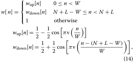
The two repeated parts are extended by introducing smooth block boundaries in the preamble in order to con-trol the OOB emissions. For this purpose, a special time windoww=(w[n])Twith ramp-up transitionwup[n] and
ramp-down transitionwdown[n] is defined. As an exam-ple, the corresponding coefficients can be taken from a variation of the Tukey pulse [15]:
w[n]= is the length of the ramp-up and ramp-down transitions, and v(n)is known as the Meyer wavelet auxiliary function [16]:
v(n)=n4(35−84n+70n2−20n3). (15)
Finally, the windowed preamble can be written as
pw=A(we)dp, (16)
where A(we) is the extended modulation matrix from (6),
which incorporates the block transitions inw.
Note that the preamble sequence presented in [12], which is designed for OFDM, can be reproduced using the GFDM matrix notationp1 = A(1e)dp, whereA(1e) is
con-structed with a rectangular window, i.e.,w[n]= 1forn∈ {0,N+L−1}.
The prototype filterg[k] can also be defined as a rect-angular function covering exactly the duration of one subsymbol for both non-windowed and the windowed preamble once the two repeated subsymbols are cyclically connected.
a
b
Figure 4Proposed preamble.(a)Preamble in time domain.(b)
Power spectrum density of the windowed and non-windowed preamble.
the extended approach. While the non-windowed pream-blep1produces non-negligible spectrum sidelobe of−35 dBc, the proposed smoothing window in pw is able to drastically reduce the OOB several orders of magnitude below what traditional OFDM can achieve.
On the receiver side, a set of samplesr[n] is collected. Among those, the transmitted preamble needs to be received at least once, in order to be able to estimate time and frequency offsets. An autocorrelation of the sequence r[n] is performed according to [10] as
ρ[n]=
n+N−1
k=n
r[k]∗r[k+N/2] . (17) From this, a normalized autocorrelation
μS[n]= 2|ρ[n]| 2
n+N−1
k=n |r[k]|2
(18)
can be derived. The presence of CP and CS creates a plateau effect in the metric, but this ambiguity can be resolved by integrating over the length of CP and CS [11], which yields
μM[n]= 1 L+1
n
k=n−L
μS[k] . (19)
With this result, the coarse STO estimation is obtained by searching for the peaknˆMof (19), i.e.,
ˆ
nM =argmax
n
(μM[n]). (20)
The angle ofρ[nˆM] reveals the effects of phase rotation
ˆ
and is used to estimate the CFO; hence,
ˆ
= ∠ρ[nˆM]
π . (21)
The CFO information can be used to correct the fre-quency offset in the received signal, yielding
r[n]=r[n]∗·exp
−j2πˆ
Nn
. (22)
This operation allows the usage of a sharper metric employing cross-correlation with the known transmitted preamble, which is given by
ρC[n]= 1 N
N−1
k=0
r[n+k]p×[k] , (23) wherep×[k] contains the two halves of the original pream-ble obtained from the operationp×=Adp.
The metrics (19) and (23) can be combined in order to suppress side peaks that result from the repeating parts inside the preamble [12], which leads to
μA[n]= |ρC[n]| ·μM[n] . (24)
A more accurate STO estimation is obtained by search-ing for the peak valuenˆAof (24) around the range [nˆM− N/2, nˆM+N/2]:
ˆ
nA= argmax
ˆ
nM−N2≤n≤ˆnM+N2
(μA[n]). (25)
Figure 5 presents a realization ofμS[n],μM[n],|ρC[n]|,
and μA[n] and illustrates the metric evolution in the schemes from [10] to [11] and [12]. Without windowing, the plateau effect inμS[n] is eliminated inμM[n], and this metric is then multiplied with|ρC[n]|to remove its side
peaks. With windowing the final result, μM[n]·|ρC[n]|
differs only slightly, while the main difference is an alter-ation in the shape of μS[n]. By choosing the window length to be within the CP and CS region, the plateau is suppressed. So, with a proper time offset adjustment, it would be possible to combineμS[n] directly with|ρC[n]|
and further simplify the algorithm without computing μM[n].
Although the impulsive shape ofμA[n] results in pre-cise STO estimation in single path channels, in time-variant frequency-selective channels, the first multipath peak cannot be found using only the maximum value prin-ciple. Fading propagation conditions can affect the initial channel tap gain such that it can be lower than one of the other echoes.
Finding the position of the first multipath is addressed in [13] with a threshold criterion proposed to identify other multipath peaks before the maximum peak with a given probability of false alarmpFA. Based on the central limit theorem, samples that do not correspond to the pream-ble echoes in the cross-correlation output are interpreted as complex Gaussian random samples, and the threshold is derived from a Rayleigh cumulative density function (CDF), resulting in [13]
TTh=
whereλis an adjustable parameter defined according to the channel impulse response characteristics.
For frequency selective channels, the estimation of the first multipath is then performed in the range(nˆA−λ, nˆA] and is given by
ˆ
nf = argfirst
ˆ
nA−λ<n≤ˆnA
(|ρC[n]|>TTh). (27)
An evaluation on the complexity of the algorithm [12] can be found in [17]. The effect of the refined search for the position of the first multipath will be better evalu-ated in the next section in terms of the STO and CFO estimation errors.
4 Performance analysis of the synchronization
algorithm
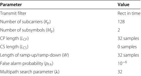
The system parameters used for the simulation are pre-sented in Table 1.
In order to analyze the performance of the proposed windowed preamble, the synchronization technique is evaluated in a time-variant frequency-selective channel. The unknown time offsetθ and frequency offsetεwill be estimated considering a channel impulse response with 32 taps. The tap gains vary linearly in decibel scale from 0
Table 1 Simulation parameters for the preamble
Parameter Value
Transmit filter Rect in time
Number of subcarriers (Kp) 128
Number of subsymbols (Mp) 2
CP length (LCP) 32 samples
CS length (LCS) 0 samples
Length of ramp-up/ramp-down (W) 32 samples
False alarm probability (pFA) 10−6
Multipath search parameter (λ) 32
to−13 dB. Each tap is multiplied by a Rayleigh distributed random variable with parameterσ=1/√2.
The mean error and the mean square error of CFO and STO estimations for non-windowed and windowed preambles have been evaluated for 1,000 realizations at each value of SNR and are presented in Figures 6 and 7, respectively.
The Cramér-Rao lower bound is included in Figure 6 and is computed according to [10] to be used as a ref-erence. The gap observed in the CFO estimation, which occurs for both non-windowed and windowed preambles, is due to the coherence loss between the segments of the preamble introduced by the time-variant frequency-selective channel.
The mean squared error of the STO estimation is within tenths of a sample as the SNR is increased for the non-windowed and the non-windowed preambles. For the particu-lar parameters used in the simulation, it is observed that the mean value of the STO in Figure 7 presents a positive offset behavior that decreases with the increment of the
Figure 7Mean error and mean squared error of the STO estimation.
SNR. This is a consequence not only of the multipath delay profile but also of the threshold criterion used for search-ing the first multipath. The threshold is proportional to the noise level, and if a low false alarm probability is spec-ified, the chance to ignore a severely attenuated first path gets higher.
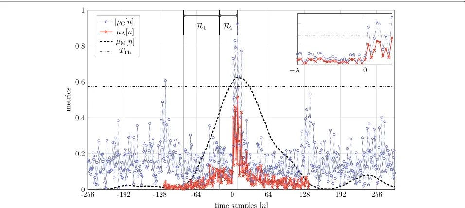
An illustration of positive residual STO estimation is provided by Figure 8. It contains one realization of the syn-chronization process in a SNR of 0 dB for the windowed preamble. Although|μM[n]|is not sharp, this metric can coarsely identify the region where the preamble is present and provides the CFO estimation. Once the CFO is com-pensated, the cross-correlation |ρC[n]|is obtained. The
search for the highest peak is performed withμA[n], but it does not represent the first multipath, located in the time sample position 0.
Two regions are explored for a refined search for the position of the first multipath in |ρC[n]|: region
1 (R1) defines the range used to compute the thresh-old value, and region 2 (R2) defines the range where peaks higher than the threshold are considered as pre-vious multipaths. The zoomed curve shows the range
ˆ
nA− λ ≤ n ≤ ˆnA. In this example,h[0]<< h[1] and the threshold criterion points thath[1] should be consid-ered as the first multipath, resulting in a positive offset error.
As can be seen in Figure 8, even when the channel delay profile has a weak first tap and the SNR is low (0 dB), the residual estimation error of the position of the primary path is small. Furthermore, in higher SNR conditions, the impact of losing a weak multipath is not as severe as a potential ISI from an adjacent transmitted sequence in a bit pipe communication system, which might happen if a negative residual error is introduced.
5 Metric to evaluate synchronization errors
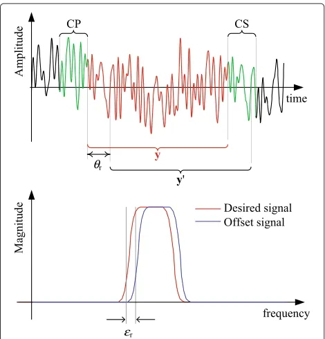
The synchronization algorithms used to estimate the time and frequency offset might result in residual errors, which are, respectively, termed here asθr=θ− ˆnfandεr=ε− ˆε. Figure 9 depicts the residual time offsetθrwithin the CP and CS interval and the residual frequency offsetεrwithin one subcarrier bandwidth.
Misalignment in the time and frequency synchroniza-tion leads to performance degradasynchroniza-tion. A metric to evaluate the influence of the residual synchronization errors is necessary to analyze the influence of imperfect
Figure 9Illustration of residual (top) time and (bottom) frequency offsets in a received signal.
synchronization on the system performance. Considering a channel without distortion as well as a givenθr andεr, the estimated symbols on the receiver side are
ˆ
d=By=By=BAd=Gd, (28)
whereyis the received signal after synchronization with residual time and frequency offsets, and Gis the over-all system matrix. The matrix that represents the overover-all residual time and frequency offsets is given by
= 1 NfreqF
H
timeF (29)
whereFis the Fourier matrix,
freq=
is the matrix representing the frequency shifts and
time=
is the matrix representing the time shifts.
For a linear detection, ifG=IN, the recovered symbols
equal the transmitted symbols. Hence, the mean square
error between G and the identity matrix can be seen as a measure of the degradation introduced by the self-generated interference in a non-orthogonal system and the time and frequency offsets. In this sense, a metric to evaluate the interference caused by residual synchroniza-tion errors can be defined by
= 1
It is important to observe that in case of perfect syn-chronization, = IN, the metric can also be used to
evaluate the prototype filter g[n] and the performance of the system, BA. For instance, Figure 10 exhibits the influence of the MF receiver with raised cosine (RC) and root-raised cosine (RRC) [14] as a function of the roll-off parameterα, assuming perfect synchronization.
From Figure 10, it is possible to conclude that small roll-off values leads to smaller interference, while RC filter outperforms RRC for any value of α. This is an inter-esting counterintuitive result, because the interference introduced by the MF with RC is composed by ISI and ICI, while the RRC is a Nyquist pulse and thus creates only ICI [14].
When the roll-off is equal to zero, the self-interference is absent, both RRC and RC became a rect filter in frequency domain. This is a corner case where GFDM implements the orthogonal concept of the localized single-carrier frequency-division multiple access (SC-FDMA) scheme [18].
Since the degradation introduced by self-generated interference depends only on the transmission matrix and the corresponding receiver matrix, the metric proposed in (32) can be combined with the noise enhancementξ to compute the impact of both the prototype filter and synchronization errors in a given SNR, as
γ=
E E+ξN0
, (33)
whereEis the average energy of the signal, andN0is the noise power spectral density.
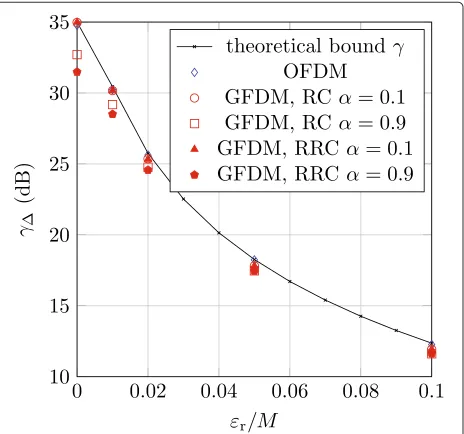
Figure 11 shows an example of SNR degradation for GFDM signals in different parameterizations with resid-ual frequency offset. The OFDM case, whereM= 1 and g[k] is a rectangular prototype filter, is presented in order to be compared with the lower bound [9]
γ ≥ E/N0sinc 2(ε)
1+0.5947E/N0sin2(π ε)
. (34)
Figure 11 shows that the metric (32) is consistent with the lower bound proposed in [9] for the OFDM case, although GFDM has further SNR decrement because of the noise enhancement or self-interference. Furthermore, if the impact of self-generated interference on the met-ric value is known, then (32) can be used to evaluate the impact of synchronization errors in the system per-formance. Notice that the self-interference degradation can be easily obtained from (32) by assuming perfect synchronization, as shown in Figure 10. When using ZF, the noise enhancement ξ is also smaller employ-ing the RC than RRC, and it can be even neglected if α→0.
The metric is then useful as a synthesis tool, allowing for the evaluation of different GFDM configurations and estimation of its performance under presence of time and frequency offsets. The parameters in Table 2 describe a payload packet that is appended to the windowed pream-ble. The RC is chosen with a smaller roll-off, and the scheme is now evaluated in a time invariant channel with the delay profile presented in Figure 12, and a simulation
Figure 11SNR degradation versus relative frequency offset in ZF receiver.
Table 2 Configuration of the GFDM data block
Parameter Value
Mapping 16-QAM
Transmit filter RC
Roll-off (α) 0.1
Number of subcarriers (K) 128
Number of subsymbols (M) 9
CP length (LCP) 32 samples
CS length (LCS) 16 samples
Length of ramp-up/ramp-down (W) 16 samples
is performed with both non-windowed and windowed preamble assuming perfect knowledge of the channel impulse response in the reception.
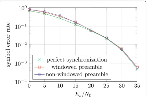
Figure 13 presents the symbol error rate (SER) perfor-mance curve considering a perfect synchronization as a reference and also the synchronization obtained with the use of the preamble. In this particular power delay profile, the first multipath is not the highest value, and it can rep-resent an indoor reception with a receiver device in a fixed position. Under this circumstance, both non-windowed and windowed algorithms perform without noticeable STO estimation errors and the SER performance curves are similar for both approaches.
The main difference between the SER obtained ing the synchronization approaches and the curve assum-ing perfect synchronization is that the high variance of the CFO in low SNR regime leads to a performance gap when the synchronization techniques are considered. However, all curves tend to match each other for high SNR, since in this case, the CFO variance became neglectable, as shown in Figure 6.
6 Conclusions
In this paper, time windowing has been proposed in com-bination with a synchronization preamble in order to
Figure 13SER analysis over time-invariant frequency-selective channel for a GFDM data block appended to the preamble.
preserve the advantageous spectral properties in a GFDM transmission. A window has been presented, which is able to provide a considerable reduction in the spectrum sidelobes, several orders of magnitude below that can be achieved with a standard preamble designed for OFDM.
The results have further shown that the windowing can contour the plateau effect in the autocorrelation metric without the need of additional integration. As an exten-sion to previous work on the original non-windowed OFDM preamble, the mean value of the residual time off-set has been investigated. The results show that the sign of the error is always positive. This implies that ISI from the previous symbol is avoided, and misestimation of the block start should be within the CP. Specially when the operation is in the low SNR, this leaves the potential to improve the estimation result with a feedback loop.
Also, a metric to evaluate the impact of the residual CFO and STO estimation errors is presented. The same met-ric can reveal details about the self-interference created by different prototype filters and receiver configurations in a non-orthogonal waveform like GFDM. The overall performance of the system using the low OOB windowed preamble scheme is simulated in terms of SER vs. SNR in a time-invariant frequency-selective channel. As an over-all result, the proposed scheme exhibited no degradation in performance when compared to the standard method used in OFDM, yet keeping a spectrum sidelobes sev-eral dBs below the one presented by the non-windowed preamble. Therefore, the synchronization scheme pro-posed in this paper can be employed in the scenarios foreseen for the next-generation wireless networks, where standard OFDM approaches are not suitable.
Competing interests
The authors declare that they have no competing interests.
Acknowledgements
This work has been performed in the framework of the ICT project ICT-318555 ‘5GNOW’, which is partly funded by the European Union. The authors would
like to thank Instituto Nacional de Telecomunicações (Inatel) and Conselho Nacional de Desenvolvimento Científico e Tecnológico (CNPq) for partially funding the work presented in this paper.
Author details
1Technische Universität Dresden, Georg-Schumann-Str. 11, Dresden D-01187,
Germany.2Instituto Nacional de Telecomunicações, Av. João de Camargo, 510
Santa Rita do Sapucai, MG 37540-000, Brazil.
Received: 1 December 2013 Accepted: 21 April 2014 Published: 10 May 2014
References
1. V Savaux, Y Louët, M Djoko-Kouam, A Skrzypczak, Application of a joint and iterative MMSE-based estimation of SNR and frequency-selective channel for OFDM systems. EURASIP J. Adv. Signal Process.2013(1), 128 (2013) 2. G Wunder, P Jung, M Kasparick, T Wild, F Schaich, Y Chen, S Brink, I Gaspar,
N Michailow, A Festag, L Mendes, N Cassiau, D Ktenas, M Dryjanski, S Pietrzyk, B Eged, P Vago, F Wiedmann, 5GNOW: non-orthogonal, asynchronous waveforms for future mobile applications. IEEE Commun. Mag.52, 97–105 (2014)
3. JVD Beek, F Berggren, Out-of-band power suppression in OFDM. IEEE Comm. Lett.12(9), 609–611 (2008)
4. G Fettweis, M Krondorf, S Bittner, GFDM - generalized frequency division multiplexing. Paper presented at the IEEE 69th vehicular technology conference, Hilton Diagonal Mar (Barcelona, Spain, 26–29 April 2009), pp. 1–4 5. N Michailow, S Krone, M Lentmaier, G Fettweis, Bit error rate performance
of generalized frequency division multiplexing. Paper presented at the 76th, IEEE vehicular technology conference (VTC Fall’12) (Québec, Canada, 3), pp. 1–5
6. R Datta, N Michailow, M Lentmaier, G Fettweis, GFDM interference cancellation for flexible cognitive radio PHY design. VTC.1, 1–5 (2012) 7. I Gaspar, N Michailow, A Navarro, E Ohlmer, S Krone, G Fettweis, Low
complexity GFDM receiver based on sparse frequency domain processing. Paper presented at the, IEEE 77th vehicular technology conference (VTC Spring) (Dresden, Germany, 2–5 June 2013), pp. 1–6 8. ARS Bahai, BR Saltzberg, M Ergen, Synchronization, inMulti-Carrier Digital
Communications: Theory and Applications of OFDM(Springer, New York, 2004), pp. 83–101
9. PH Moose, A technique for orthogonal frequency division multiplexing frequency offset correction. IEEE Trans. Comm.42(10), 2908–2914 (1994) 10. T Schmidl, D Cox, Robust frequency and timing synchronization for
OFDM. IEEE Trans. Comm.45(12), 1613–1621 (1997)
11. H Minn, M Zeng, V Bhargava, On timing offset estimation for OFDM systems. IEEE Commun. Lett.4(7), 242–244 (2000)
12. A Awoseyila, C Kasparis, B Evans, Improved preamble-aided timing estimation for OFDM systems. IEEE Commun. Lett.12(11), 825–827 (2008) 13. C Kasparis, BG Evans, A cross-correlation approach for improved timing
estimation in, OFDM broadcasting systems. Paper presented at the 24th AIAA international communications satellite systems conferences (ICSSC), (San Diego, CA, USA, 11–14 June 2006), pp. 1039–1048
14. M Matthé, N Michailow, I Gaspar, G Fettweis, Influence of pulse shaping on bit error rate performance and out of band radiation of generalized frequency division multiplexing. Paper presented at the ICC’14 -workshop on 5G technologies (ICC’14 WS - 5G), (Sydney, Australia, 10) 15. P Bloomfield,Fourier Analysis of Time Series: An Introduction
(Wiley-Interscience, New York, 2000)
16. Y Meyer,Ondelettes et opérateurs: Ondelettes(Actualités mathématiques, Hermann, 1990)
17. H Abdzadeh-Ziabari, MG Shayesteh, Robust timing and frequency synchronization for ofdm systems. IEEE Trans. Veh. Tech.60(8), 3646–3656 (2011)
18. HG Myung, J Lim, D Goodman, Single carrier FDMA for uplink wireless transmission. IEEE Veh. Tech. Mag.1(3), 30–38 (2006)
doi:10.1186/1687-6180-2014-67

![Figure 5 presents a realization of metric is then multiplied withschemes from [10] to [11] and [12]](https://thumb-us.123doks.com/thumbv2/123dok_us/898376.1108272/5.595.302.540.454.704/figure-presents-realization-metric-multiplied-withschemes.webp)
![The effect of web based depression interventions on self reported help seeking: randomised controlled trial [ISRCTN77824516]](data:image/gif;base64,R0lGODlhAQABAIAAAP///wAAACH5BAEAAAAALAAAAAABAAEAAAICRAEAOw==)