R E S E A R C H
Open Access
A novel CSI-based fingerprinting for
localization with a single AP
Lei Zhang
1,2,3, Enjie Ding
1,2,3, Yanjun Hu
1,2,3*and Yafeng Liu
1,2,3Abstract
WiFi-based indoor localization techniques are critical for location-based services. Among them, fingerprint-based method gains considerable interest due to its high accuracy and low equipment requirement. One of the major challenges faced by fingerprint-based position system is that in some places there are not enough access points (AP) to provide features for accurate location. To address that, we propose a novel fingerprint-based system using only a single AP. We propose a novel phase decomposition method to obtain the phase of multipath provided by a AP and use the decomposed phase as a fingerprint after the feature exaction by principal component analysis (PCA). Performance in the laboratory, meeting room, and corridor is investigated, and our system is also compared with a RSSI-based and a CSI-based fingerprint localization system. As the experimental results suggest, the minimum mean distance error is 0.6 m in the laboratory, 0.45 m in the meeting room, and 1.08 m in the corridor, outperforming the other two systems.
Keywords:WiFi network, Indoor localization, Channel state information, Phase decomposition, MIMO-OFDM
1 Introduction
In outdoor environments, GPS-based localization tech-niques make our lives more convenient in many aspects [1, 2]. Since the GPS signals cannot penetrate efficiently indoors to localize objects [3], some other techniques are used to replace GPS to provide accurate location in-formation [4, 5] in indoor environment. Among the in-door localization techniques, the WiFi-based localization techniques have become one of research hotspots due to the ubiquitous WiFi infrastructure. However, in some occasions, there may not be enough APs to implement the location methods [6–8], hence it is necessary to study the location method based on single AP.
Since the received signal strength indication (RSSI) is capable of reflecting the distance between the AP and the node, traditional WiFi-based models use RSSI as a metric. A RSSI-based model or fingerprint can be built, and examples for RSSI-based localization systems are
DWELT system [9] as well as Horus system [10].
Nevertheless, RSSI fluctuates significantly in some
scenarios as being susceptible to multipath effect [11]. The positioning accuracy of most systems ranges from
3 to 10 m [12]. To overcome the fluctuation of RSSI,
Hossain et al. proposed SSD [13] that localizes nodes
using the signal strength difference. However, RSSI is limited as it fails to reflect the spatial, temporal, and environmental characteristics.
Signals transmitted in WiFi networks exploit
orthog-onal frequency division multiplexing (OFDM) [14],
which are transmitted and received by multiple subcar-riers. The received signal impacted by scattering, fading, and power loss with distance can be represented by the physical layer information known as channel state information (CSI). By modifying driver firmware, CSI can be obtained using Intel 5300 or Atheros 9390 cards [15, 16]. Due to multipath, subcarriers will propagate along different paths, which makes the amplitude and phase of each subcarrier different from each other.
It is witnessed in recent years that CSI-based tech-niques have been widely adopted in localization. In com-parison with coarse-grained RSSI, CSI is a fine-grained indicator containing amplitude and phase information during signal propagation [17–20]. Moreover, similar to RSSI-based techniques, model-based techniques are also
used. LiFS using the subcarriers with minimal
* Correspondence:[email protected]
1
School of Information and Control Engineering, China University of Mining and Technology, Xuzhou 221000, China
2IoT Perception Mine Research Center, China University of Mining and
Technology, Xuzhou 221000, China
Full list of author information is available at the end of the article
interference by multipath is designed by Wang et al. [21] for accurate localization of fingerprint. The combination of the amplitude with spatial diversity is used by Wu et
al. [22] for indoor location. Furthermore, to achieve
higher accuracy by obtaining high data dimension, FIFS [23] and CSI-MIMO [20] systems, both aggregate ampli-tude and phase information of all subcarriers of all an-tennas for indoor location fingerprinting. Angle of arrival (AOA) estimation is also applied in CSI-based
localization such as ArrayTrack [24] whose key method
is that make the number of antennas greater than the number of paths, and then deduces AOAs using MUSIC algorithm. By increasing the number of APs or the num-ber of antennas, CSI-MIMO and ArrayTrack achieve high positioning accuracy, respectively. In practice, most of today’s WiFi networks deployment is primarily for communications rather than for positioning. Thus, there may be insufficient APs to provide CSIs to generate a fingerprint, and increasing the number of antennas re-sults in additional hardware costs which may not be available in practical applications as well.
In the present study, we try to advance CSI-based in-door localization to achieve centimeter-level localization resolution only by using a single commercial AP under the phase of multipath offered by CSI of subcarriers using multiple input multiple output (MIMO) to derive the location signatures.
The main contributions of this paper are as follows:
1. We design a method to obtain phases of multipath by decomposing construction CSI matrix of a single AP. 2. We propose to use phase information of multipath
for indoor fingerprinting. To the best of our knowledge, this is the first work to leverage phase information of a single AP for indoor fingerprinting. 3. We analyze the effectiveness of the proposed location
signature using deterministic k-nearest neighbor (KNN), probabilistic Bayes algorithms, and support vector machine (SVM) in the experimental scenarios. 4. We investigate impact factors on the localization
accuracy of our system such as the number of decomposition path, the size of training and estimation samples, the number of APs, and the size of the cell.
5. We evaluate the performance of our system with RSSI-based and CSI-based localization system.
The rest of this study is structured as follows. The re-lated work is briefly presented is in Section2. Section3 in-troduces preliminary study including CSI. In Section 4, our proposed localization system is detailed. The evalu-ation results of our system are discussed in Section5. The conclusion is drawn and the future research is directed in the final Section.
2 Related work
Increasing demand of location-based service (LBS) draws a great deal of attention to WiFi-based localization in in-door environments. We catalog this into two classes, device-free localization and device-based localization.
2.1 Device-free localization
As it is not convenient for a subject to carry a device,
Jie et al. [25] implement a localization system with
non-equipped entity. Some other systems [26–30] have been proposed which constitute fingerprint-based or model-based solutions. Model-based algorithms, which do not require any laborious effort to build and main-tain a radio map, estimate the distance from the object to an AP by using statistical models. LiFS [21] achieves the accuracy of about 1 m in indoor environments by using selected subcarriers of CSI to build a model. Due to the changes of direction, reflecting, or scattering sig-nals, it is hard to obtain an accurate relationship be-tween the signal and the location. Fingerprint-based algorithms, however, need no prior knowledge of the relationship between the distance and signals, gain much attention in the localization systems. General fingerprint-based technique has two phases named the offline and localization phase. Offline phase is to collect signals for generating fingerprints from every spot of an interested area to build a radio map. During the localization phase, observed fingerprint is matched against the radio-map by using matching algorithms. Zhou et al. [31] establish the nonlinear relationship be-tween CSI fingerprints during the offline phase and es-timate locations through SVM regression. Unlike
fingerprinting localization, MaTrack [32] uses
Dynamic-MUSIC method to identify the angles for localization through detecting the subtle reflection sig-nals from the human body.
2.2 Device-based localization
Due to security or commercial reasons, in some scenar-ios, we not only need the position but also the identity information of a person in which the device-free
localization system is not suitable. Device-based
localization system can provide identity information as human carrying specialized equipment. Compared to using RSSI of WiFi for localization such as Horus [10]
and RADAR [33], CSI-based localization systems
pro-vide higher accuracy. PILA [18] designs an algorithm to identify direct path from multipath and uses MUSIC al-gorithm to jointly estimate the AOA and time of arrival
(TOA) of each path. PhaseFi [34] implements a scheme
ToneTrack [35] increases the effective bandwidth to ob-tain the TOA of APs by leveraging the frequency-agile
technique. Similar to ToneTrack, CHRONOS [36] uses
Chinese remainder theorem to measure the time of fly (TOF) across different channels and then estimate dis-tance between devices and AP through leveraging the TOF measurements. In addition to considering position-ing accuracy, positionposition-ing efficiency is also of great
import-ance to localization systems. For instimport-ance, CRIL [37]
accounts for dynamic environments introduces coupled RSSI and INS localization system to improve the efficiency of location estimation.
3 Preliminaries
3.1 CSI
In wireless communication systems, CSI reveals the channel response properties of transmission links, which includes the combined effect of scattering, fad-ing, and power decay with distance. In most WiFi net-works, multiple input multiple output (MIMO) and OFDM technologies are employed to transmit data more effectively. In these networks, CSI represents the subcarriers properties of each transmitting and
receiv-ing antennas. Halperin et al. [38] released a tool by
which both the amplitude and phase measurements of each MIMO-OFDM subcarrier can be aggregated from Intel’s IWL 5300.
According to the bandwidth of WiFi, it is considered as a narrowband flat fading channel, and the channel model is defined as follows:
y¼CSIxþn ð1Þ
wherey andxdenote the received and transmitted signal vectors, respectively, CSI denotes the channel frequency response, andnis the additive white Gaussian noise.
In 802.11n standard, 56 or 114 subcarriers are used for data transmission in the OFDM system. Each antenna of the IWL 5300 exports 30 out of all subcarriers and the index of subcarriers varies with bandwidth and grouping
Ng. TheCSIkdenotes the channel frequency response of
the subcarrierkshown as follows:
CSIk ¼
XL
l¼1
αle−j2πðf0þkΔfÞτl ð2Þ
where αl and τl denote the signal magnitude and the
TOF of path l, respectively. f0is the central frequency,
Δf is the frequency interval of adjacent subcarriers, and the 30 subcarriers are written as follows:
CSI¼½CSI1;CSI2;…CSI30; ð3Þ
3.2 MIMO
MIMO technology using multiple transmitting and re-ceiving antennas greatly increases the capacity and spectrum utilization of the communication systems without increasing the bandwidth. Due to the multipath effects, it is difficult to achieve high-speed data transmis-sion in cluttered indoor environments [39]. However, in MIMO systems, multipath effects can serve as a favor-able factor, as the signal among different transmitting antennas uses multipath propagation. Moreover, if the antennas of both transmitting and receiving are inde-pendent, the data transmission will be improved in these parallel spatial channels created by the MIMO system.
Sett andras the number of transmitting and receiving
antennas, respectively. Each transmitting and receiving antenna pair is comprised of a data-stream. The CSIs data of all antennas are defined as follows:
ð3Þ
where theCSIrtis a vector denoting the CSI of 30
sub-carriers between the transmitting antenna t and
receiv-ing antennar.
4 Motivation and localization system design In this section, we investigate the challenges posed by CSI phase measurements to improve the location
esti-mation. In accordance with (2), CSI is the
superpos-ition of multipath signals. If there is only a direct path, phase can serve as a fingerprint for localization. However, in practical indoor environments, indoor propagation is dominated by severe multipath as
shown in Fig. 1, and raw phase information is not
suitable for generating fingerprints. To use phase as a fingerprint, we design a method to obtain the phase from multipath.
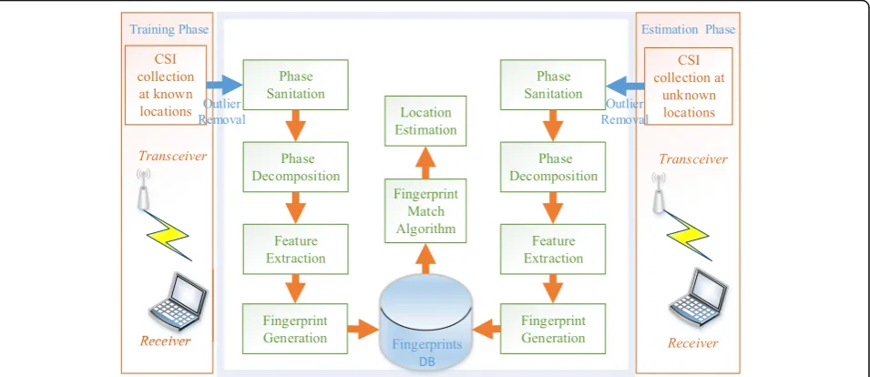
The architecture of the system is designed with four
key constituent blocks, as shown in Fig. 2. We will
describe each block in detail in the following
subsections.
4.1 Overview
4.1.1 Training phase
In training phase, a mobile device is placed at a known lo-cation for the collection of CSI data. After outlier removal, a phase sanitation block is used to calibrate phase, and then the phase information of the multipath is obtained through a phase decomposition block, which is presented later in this section. A unique fingerprint of one location is generated using the feature extraction method based on dimensionality reduction. This work is repeated on each location until we store the whole fingerprint coupled with the coordinates in the fingerprint database.
4.1.2 Estimation phase
During the online phase, we randomly select some un-known locations to collect CSI data. Similar to the train-ing phase, the collected CSI data is processed ustrain-ing the same method to generate a position fingerprint. A fin-gerprint matching algorithm is employed to compare it with the location fingerprint database to estimate the object location.
4.2 Outlier removal
As the outliers appear during our collection due to the indoor environmental noise, which is capable of affecting the localization system performance. Consequently, we
implement Pauta Criterion [40] to remove these biased
measurements, as shown in the following:
Vm ¼ Xm−X
>3S ð4Þ
S¼
ffiffiffiffiffiffiffiffiffiffiffiffiffiffiffiffiffiffiffiffiffiffiffiffiffi
Xn
i¼1 Xi−X
2
n−1
v u u u t
ð5Þ
where Xm denotes the one of all the measurement, and
X is the median. We declareXmas an outlier if it meets
the condition according to (4). The CSIs of four subcar-riers before and after performing outlier removal are shown in Fig. 3. It is observed that the Pauta Criterion works well to remove the significant outliers.
Fig. 1Signal propagation
4.3 Phase sanitization
The hardware imperfection makes it impossible to gain the genuine CSI phase. Practically, there are two major causes of the measurement errors. One is the carrier frequency offset (CFO) as the center frequency is not synchronized between the transmitter and receiver. The
sampling frequency offset (SFO) generated by
non-synchronized clocks of ADC makes the measure-ment errors different for different subcarriers. The mea-sured phase of subcarrierkis written as follows:
∠CSIdk¼∠CSIkþ2πnk
NΔtkþβþZ ð6Þ
where the∠CSIdk and the∠CSIkdenote the measured and
the genuine values of the subcarrierk, respectively.nkis
the index of sub-carriers, andΔtkindicates the time offset
due to SFO.Nis the FFT size from the IEEE 802.11n spe-cification.βis the unknown phase offset for CFO, andZis the measurement noise. It is unlikely to obtain the true phase information as the unknownΔtkandΔtk. To
elim-inate phase offset Δtk and Δtk, the linear transformation
algorithm [41] is used to achieve this goal.
The offsetband the slopeaare defined as follows:
a¼∠CSIdN‐∠CSId1 nN‐n1 ¼
∠CSIN‐∠CSI1
nN‐n1 ‐
2π
N Δt ð7Þ
b¼301 X30
i¼1∠ d CSIk¼301
XN
k¼1
∠CSIkþ230πΔtN
XN
nk¼1
nkþβþZ ð8Þ
In the OFDM system, the symmetric frequency of the subcarriers leadsPNnk¼1nk¼0. Then, theb is written as follows:
b¼301 X30 i¼1
∠CSIdk¼1 30
XN
k¼1
∠CSIkþβþZ ð9Þ
By subtracting the linear term ank+b from the raw
phase, we obtain the calibrated values as follows:
∠CSIgk¼∠CSIk−∠CSIN−∠CSI1 nN‐n1 nk‐
1 30
XN
k¼1
∠CSIk ð10Þ
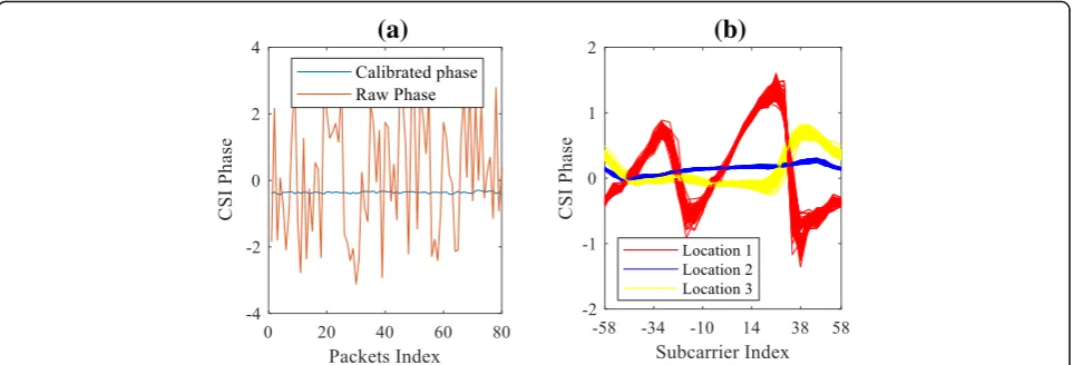
The CSI phase after sanitation is shown in Fig. 4a.
Calibrated phases are less fluctuant and more concen-trated, in comparison with the raw phases which scatter randomly over many different angles. The calibrated phases for about 80 packets at 3 different locations are shown in Fig. 4b. As can be seen, the calibrated phases are stable at one given location and differing in different locations, suggesting that it can be very suitable for in-door fingerprint positioning.
4.4 Phase decomposition
Compared with RSSI, CSI is a fine-grained information, yet the CSI value of each subcarrier is also a superpos-ition of some paths due to the bandwidth of WiFi net-work. In this part, we strive to acquire the phase information of as many paths as possible by designing a phase decomposition method.
SetCSI0as the subcarrier of index 0. According to 2),
CSIk is a linear combination of the phase of each path
and the phase of subcarrier 0. To simplify the notations,
CSIkis represented as follows:
CSIk ¼
In the 802.11n standard, when BW = 40 MHz and Ng = 4 (grouping), the index of the sampled subcarriers
ranges from −58 to 58, in which the interval of
sub-carrier index is 4. For the convenience of presentation, assuming that there are five paths here, and a Hankel matrix can be built:
X¼
Actually,Xis written as follows:
X¼ΔSΔT ð14Þ
It is easy to prove that
V¼
V is a Vandermonde matrix [42]. Therefore, the
prob-lem arises to find a Vandermonde decomposition of X.
The decomposition algorithm [43] is shown as follows:
(a)
(b)
According to phase decomposition, the phase can be extracted from each path. On the other hand, it cannot be used for the calculation of TOF as it contains some unknown phase offset caused by ADC.
4.5 PCA-based feature extraction
Assuming that our system has N transmitting antennas
and Rreceiving antennas. In line with the phase
decom-position method, the dimension of a vector is N*R*L = p
whereLdenotes the assumed number of paths. As each lo-cation consists ofTpackets, we haveT p-dimensional vec-tor, and the size of a location matrixVisT*Pwhich may be a very high dimension for real time localization. To reduce
the dimension and yield the robust feature, principal com-ponent analysis (PCA) is conducted for the location matrix. For the high dimension data, PCA selects the greatest vari-ance dimension data as the principal components.
For the location matrixV, we first calculate the median vector of the matrix and subtract it from each row to
realize the mean-centered value. Set M and σ as the
mean-centered matrix and the convenience matrix ofM,
respectively. Assuming thatλidenotes the eigenvalue of σ, and xi is eigenvector corresponding to eigenvalues.
Thus, there is a vectorxiwhich satisfiesσxi=λixi. Let T
eigenvectors and eigenvalue form matrixΦandΛ:
Φ¼½x1 x2 ⋯ xT
Λ¼ diagðλ1 λ2 ⋯ λTÞ ð21Þ
By normalizing every eigenvector to unit magnitude and orthogonal with each other, it is yielded that
Φ0Φ¼ΦΦ0¼I
σ¼ΦΛΦ0 ð22Þ
With rlargest eigenvalues of σ,T-r projection matrix is yielded:
Φ¼xp1 xp2 ⋯ xpr ð23Þ
For each location, we project the location matrix into a corresponding matrix as a fingerprint matrix:
F¼MΦp ð24Þ
5 Experiment implementation and performance metrics
5.1 Experimental equipment and scenarios
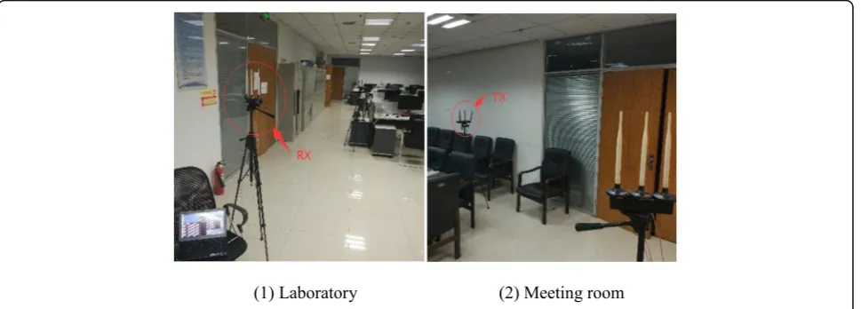
Our system is evaluated in the laboratory, meeting room,
and corridor as shown in Fig. 5. The D-Link dir-859
wireless APs and the SONY laptops mounted WiFi Wireless Link 5300 Cards serve as transmitters and
receivers, respectively. The APs operation in IEEE 802.11n mode has three antennas. In some places close to AP, the transmitting antenna and receiving antenna are very close, the signals from different antennas at-tenuating very similarly, causing the AP to actively merge similar channels. In this case, we are unable to obtain the CSI of all three antennas and the channel merging process is controlled by internal program of an AP that could not be intervened. Thereby, we use two of the three antennas as transmitting antennas.
We select the three experimental scenarios due to dif-ferent floor areas and mobility. The scenarios can be cat-egorized into static and dynamic based on the mobility, which depends on the number of people present and the frequency of their mobility during experimentation. In the meeting room, it is almost static with one people sit-ting at their place most of the time during experimenta-tion. In contrast, the laboratory is fully occupied with
the people at every desk location with the frequent mo-bility such as moving in and out of the place, therefore it can be a typical dynamic environment. Similar with the laboratory, corridor also can be seen as a dynamic envir-onment since people frequently walk by.
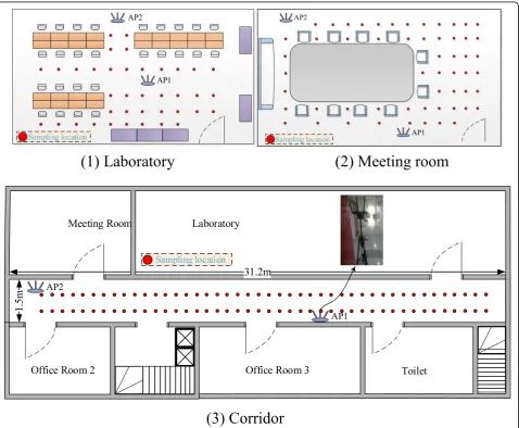
In training phase, the areas fall into many cells with the size of about 0.6 m × 0.6 m and label each cell with a number. At each cell, we collect 1000 packets from each AP. During the estimation phase, some cells are randomly selected, and 200 packets are gained at each cell. The layout and major parameters
of three scenarios are shown in Fig. 6 and Table 1,
respectively.
5.2 Performance metrics
Two metrics are used to evaluate the performance of our indoor localization system.
5.2.1 Cell estimation accuracy
The cell estimation accuracy (CEA) suggests the ratio of the number of correctly estimated testing cells to all cell locations during the estimation phase, which is calcu-lated as follows:
CEA ¼ 1 N
XN
i¼1
I yð i¼^yiÞ ð25Þ
whereNdenotes the number of total testing cells. 5.2.2 Median distance error
The estimation phase may suggest that some testing cells are being misclassified. Given such circumstances, the aver-age distance between the center points of the estimated cells and true cells are calculated, which is termed as median dis-tance error. Formally, the median disdis-tance error is given by
MDE ¼ 1 N
XN
i¼1 yi−^yi
k k2 ð26Þ
where‖·‖2denotes the L2 norm.
Combining with the size of cell size, the CEA could be used to express the precision of positioning and the
median distance error (MDE) is utilized to represent the overall performance of positioning system.
5.3 Overall performance
The most machine learning algorithms can be catego-rized into deterministic and probabilistic algorithms, so we selected KNN, SVM, and Bayes as matching algo-rithms. KNN and SVM are deterministic algorithms which use the distance between a test fingerprint and each training fingerprint from the fingerprint database to estimate the test location. Bayes algorithm was a probabilistic algorithm that estimates the test location by maximizing the posterior probability.
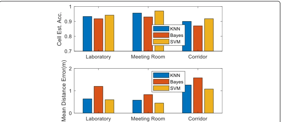
Three fingerprint matching algorithms are used to examine the overall performance of our system in the three scenarios with only one AP. The cell estimation accuracy and median distance error in three scenarios are shown in Fig. 7. It is observed from Fig.7 that the CEA in laboratory is higher than that in the meeting room, while the MDE is lower than that in the meeting room and among all scenarios, the corridor also reaches the maximum MDE and the minimum CEA. This is pri-marily because the furniture, the number of people, and the frequency of their mobility in the meeting room are less than those in the laboratory. Thus, the multipath ef-fect is small during our experiment. In comparison with the other matching algorithms, SVM reaches the best cell estimation accuracy and the lowest median distance error in both scenarios. The overall performance in the two different environments is summarized in Table2.
Table 1Main parameters of the scenarios
Parameters Laboratory Meeting room Corridor
Size 23.6 m × 5.8 m 7.2 m × 5.8 m 31.2 m × 1.5 m
Access points 2 2 2
Cells 81 42 88
5.4 Impact of the number of decomposition path
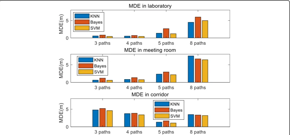
As the number of specific paths in the environment can-not be accurately obtained, we can only intuitively as-sume the number of paths in the environment. We investigate the impact of the number of decomposition paths, as shown in Fig. 8. It is observed that more de-composition paths do not result in higher positioning accuracy. In contrast, due to the noise in the indoor en-vironment, considerable decomposition path may make it difficult for differentiation of each fingerprint, as the fingerprint dimension increasing more noise is intro-duced to the fingerprint. We believe that 2–3 decompos-ition paths are appropriate in a scenario where the multipath effect is not obvious, and 4–5 decomposition paths are appropriate in a multipath effect environment.
5.5 Impact of size of training and estimation samples
We have evaluated four combinations: 1 k/200, 500/100,
200/50, and 50/50. Figure 9 presents the MDE of four
combinations. Bayes algorithm needs to calculate the
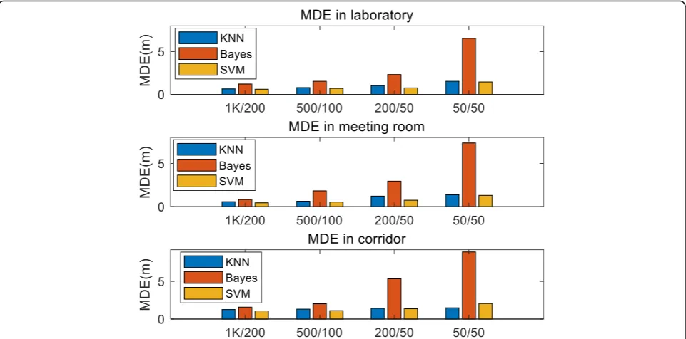
prior probabilities, and if there is not enough data for calculating the prior probabilities, the location accuracy would decrease Moreover, in Bayesian algorithm, it is as-sumed that the features are independently and identi-cally distributed; however, this assumption is often not valid in practice. Therefore, it can be seen from the Fig.9, on the condition of small size of training and esti-mation samples Bayes achieves the highest MDE com-pared to KNN and SVM.
KNN calculates the Euclidean distance between the features of test location and the features in the finger-print database to estimate location. The same as Bayes algorithm, it also needs a large amount data to improve the location accuracy. SVM is different from KNN, as it can build the model for classification only using a few samples. Additionally, SVM is good at dealing with high-dimensional and non-linear data.
The SVM approach performs the best in all of combi-nations as shown in Table 3. The best accuracy is 0.6 m in the laboratory and 0.45 m in the meeting room. They are both reached under the combination of 1 K/200 with SVM algorithm. In comparison with the other two algo-rithms, Bayes algorithm needs more data to achieve high accuracy as it calculates the prior and posterior probabil-ities. In brief, a larger amount of data improves the esti-mation of the data characteristics and is conducive to building a more accurate model to improve the position-ing accuracy.
Table 2Overall performance
Scenario Performance metric KNN Bayes SVM
Laboratory CEA 0.933 0.918 0.942
MDE (m) 0.64 1.20 0.60
Meeting room CEA 0.956 0.93 0.97
MDE (m) 0.58 0.83 0.45
5.6 Impact of the number of APs
Although our system only uses one AP to reach ac-curate localization, the number of APs is also a cru-cial factor for localization. In all scenarios, two APs are used to investigate the impact for positional ac-curacy. The MDE for different numbers of APs is
demonstrated in Fig. 10. It is observed that adding an
AP will only reduce the MDE by about 0.05 m when
KNN and SVM approaches are used for localization. This level of reduction is inconsequential in some ap-plication scenarios. However, it would be very useful for Bayes to increase the accuracy whose MDE drop from 1.21 to 1.08 m in the laboratory and from 0.83 to 0.63 m in the meeting room, respectively.
5.7 Impact of the size of cell
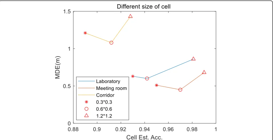
The size of cell is also an important factor that affects the positon accuracy. We conduct experiments in la-boratory, meeting room, and corridor respectively to analyze the impact of the sizes of cell. We select three size of cell which are 0.3 m × 0.3 m, 0.6 m × 0.6 m, and 1.2 m × 1.2 m. The results are shown in Fig.11. As can be seen from the figure, the size of 0.6 m × 0.6 m reaches the minimum mean distance error. Since the variance of the feature in a fingerprint is not small enough com-pared to the distance between two adjacent cells, if the size is too small, the features of the fingerprint would be very similar to that of the fingerprint of the adjacent cell in feature space, which would make it difficult to distin-guish. Hence, too small size would not help to improve positioning accuracy, but would only increase the labor and time during building the fingerprint database. On the other hand, if the size is too big, the measurement scale would be more extensive which would not be beneficial to improve the position accuracy, too.
Fig. 9MDE for different size of training and estimation samples. In the top figure, blue, orange, and yellow bar represent the median distance error of different size of training and estimation samples by using KNN, Bayes, and SVM as the match algorithm in the laboratory, respectively. In the middle figure, blue, orange, and yellow bar represent the median distance error of different size of training and estimation samples by using KNN, Bayes, and SVM as the match algorithm in the meeting room, respectively. In the bottom figure, blue, orange, and yellow bar represent the median distance error of different size of training and estimation samples by using KNN, Bayes, and SVM as the match algorithm in the corridor, respectively
Table 3MDE for different sizes of training and estimation
samples
Scenario Sample size KNN (m) Bayes (m) SVM (m)
Laboratory 1K/200 0.64 1.21 0.6
500/100 0.79 1.53 0.7
200/50 1.02 2.31 0.76
50/50 1.53 6.54 1.45
Meeting room 1K/200 0.58 0.83 0.45
500/100 0.63 1.83 0.54
200/50 1.22 2.95 0.75
50/50 1.38 7.36 1.31
Corridor 1K/200 1.26 1.58 1.08
500/100 1.31 2.03 1.11
200/50 1.42 5.34 1.36
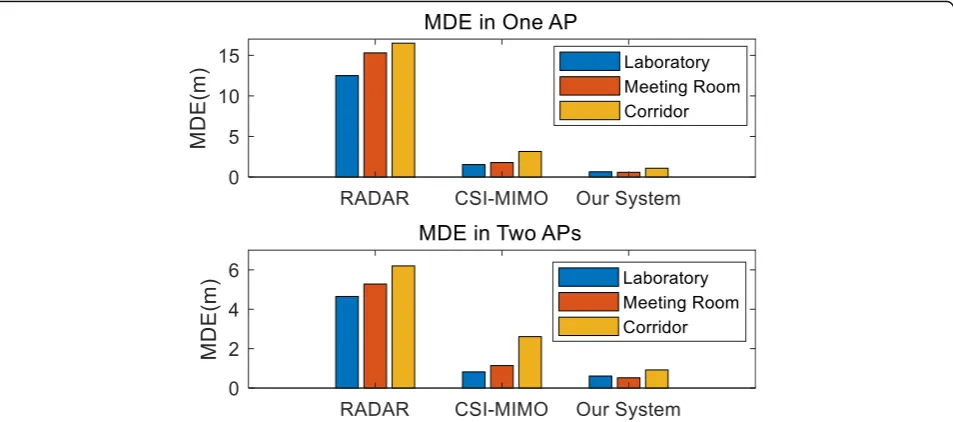
5.8 Comparison with other localization system
Our localization system is compared with two
fingerprint-based systems, i.e., a RSSI-based system
(RADAR) [33] and a CSI-based system (CSI-MIMO)
[20] in the three environments. In the experiments, the RSSI used in the RADAR system is the mean signal strength of the three receiving antennas and in the
CSI-based system, we use the same CSI data as that in our system. KNN approach is introduced to all the three systems for matching fingerprints. The performance of the three systems under the conditions of one AP and two APs are shown in Fig.11.
Since an AP only provides one RSSI, the RADAR sys-tem lacks features for localization whose MDE is
Fig. 10MDE for different number of APs. In the top figure, blue and orange represent the median distance error of different match algorithm under the one AP and two APs conditions in the laboratory, respectively. In the middle figure, blue and orange represent the median distance error of different match algorithm under the one AP and two APs conditions in the meeting room, respectively. In the bottom figure, blue and orange represent the median distance error of different match algorithm under the one AP and two APs conditions in the corridor, respectively
15.3 m in laboratory, 12.5 m in the meeting room, and 16.5 m in the corridor, respectively. Two APs contrib-ute to reducing the MDE for RADAR, the MDE de-creases significantly in all three scenarios. Similar to RADAR, more APs are also conducive to improving the localization accuracy for our system. With two APs, the MDE of our system is 0.61 m in the laboratory, which is better than 0.82 m reached by CSI-MIMO. In terms of one AP, the advantage of our system is apparent, reaching 0.64 m in the laboratory, 0.58 m in the meet-ing room, and 1.12 m in the corridor. Moreover, this is superior over 1.53 m, 1.78 m, and 3.15 m of
CSI-MIMO system, respectively (Fig.12).
6 Conclusion
In this study, a fingerprint-based localization system is presented that only using a single AP. We use the phase information for fingerprinting localization and a linear transformation algorithm to eliminate the noise in the phase. A new phase decomposition method is proposed to acquire the phase information of multipath, and a PCA-based algorithm is used to extract features for the generation of a fingerprint. The performance in the la-boratory, the meeting room, and the corridor is validated. The results reveal a minimum mean distance error of 0.6 m in the laboratory, 0.45 m in the meeting room, and 1.08 m in the corridor. We also analyze the impact factors on the localization accuracy of our system and compare our system with a RSSI-based and a CSI-based fingerprint localization system. The results demonstrate that our sys-tem outperforms the other two syssys-tems.
Our future work will focus on more complex scenarios where multiple sensing elements are used to obtain more exact information for localization. Research is on-going to verify whether the current system can also be extended to a multi-level floor.
Abbreviations
CSI:Channel state information; LBS: Location-based service; MIMO: Multiple input multiple output; OFDM: Orthogonal frequency division multiplexing; RSSI: Received signal strength indication
Acknowledgements
The authors would like to thank the reviewers for their helpful advice.
Funding
This work is supported by the National key research and development plan under Grant (No: 2017YFC0804401).
Availability of data and materials
The data used to support the findings of this study can be obtained by emailing the corresponding author.
Authors’contributions
All authors read and approved the final manuscript.
Competing interests
The authors declare that they have no conflict of interests.
Publisher’s Note
Springer Nature remains neutral with regard to jurisdictional claims in published maps and institutional affiliations.
Author details
1School of Information and Control Engineering, China University of Mining
and Technology, Xuzhou 221000, China.2IoT Perception Mine Research Center, China University of Mining and Technology, Xuzhou 221000, China.
3National and Local Joint Engineering Laboratory of Internet Application
Technology on Mine, Xuzhou 221008, Jiangsu, China.
Received: 27 September 2018 Accepted: 14 February 2019
References
1. G.A. Amagsila, M.E. Cabuhat, J.E. Tigbayan, et al., A framework for mobile application of flood alert monitoring system for vehicle users using Arduino device [C]//humanoid, nanotechnology, information technology, communication and control, environment and management (HNICEM), 2017 IEEE 9th international conference on. IEEE, 1–6 (2017)
2. F.A. Milaat, H. Liu, Decentralized detection of GPS spoofing in vehicular ad hoc networks [J]. IEEE Commun. Lett.99, 1–1 (2018)
3. S. He, S.H.G. Chan, Wi-fi fingerprint-based indoor positioning: recent advances and comparisons [J]. IEEE Communications Surveys & Tutorials
18(1), 466–490 (2017)
4. K. QIAN et al., Enabling phased array signal processing for mobile WiFi devices. IEEE Trans. Mob. Comput.17(8), 1820–1833 (2018)
5. M.O.G.H.T.A.D.A.I.E.E. Vahideh, G. DEMPSTER Andrew, Determining the best vector distance measure for use in location fingerprinting. Pervasive and Mobile Computing23, 59–79 (2015)
6. S. He, S.H.G. Chan, L. Yu, et al., SLAC: calibration-free pedometer-fingerprint fusion for indoor localization [J]. IEEE Trans. Mob. Comput.17(5), 1176–1189 (2018)
7. S. He, W. Lin, S.H.G. Chan, Indoor localization and automatic fingerprint update with altered AP signals [J]. IEEE Trans. Mob. Comput.16(7), 1897– 1910 (2017)
8. X. Tian, M. Wang, W. Li, et al., Improve accuracy of fingerprinting localization with temporal correlation of the RSS [J]. IEEE Trans. Mob. Comput.17(1), 113–126 (2018)
9. W. Su, E. Liu, A.M. Calveras Augé, et al., Design and realization of precise indoor localization mechanism for Wi-Fi devices [C]//KSII transactions on internet and. Inf. Syst.10(12), 5422–5441 (2016)
10. M. Youssef, A. Agrawala, The Horus location determination system [J]. Wirel. Netw14(3), 357–374 (2008)
11. Z. Yang, Z. Zhou, Y. Liu, From RSSI to CSI:Indoor localization via channel response [J]. ACM Comput. Surv.46(2), 1–32 (2013)
12. S. Yiu, M. Dashti, H. Claussen, et al., Wireless RSSI fingerprinting localization [J]. Signal Process.131, 235–244 (2017)
13. A.K.M.M. Hossain, Y. Jin, W.S. Soh, et al., SSD: a robust RF location fingerprint addressing mobile devices' heterogeneity [J]. IEEE Trans. Mob. Comput.
12(1), 65–77 (2013)
14. "802.11n-2009 - IEEE Standard for Information technology-- Local and metropolitan area networks-- Specific requirements-- Part 11: Wireless LAN Medium Access Control (MAC) and Physical Layer (PHY) Specifications Amendment 5: Enhancements for Higher Throughput," 2009, 1–565 15. S. Sen, J. Lee, K.H. Kim, et al., Avoiding multipath to revive inbuilding WiFi
localization [C]// proceeding of the, international conference on Mobile systems, applications, and services. ACM, 249–262 (2013)
16. D. Halperin, W. Hu, A. Sheth, et al., Tool release: gathering 802.11 n traces with channel state information [J]. ACM SIGCOMM Computer
Communication Review41(1), 53–53 (2011)
17. R. Zhou, J. Chen, X. Lu, et al., CSI fingerprinting with SVM regression to achieve device-free passive localization [C]// IEEE, international symposium on a world of wireless, Mobile and multimedia networks. IEEE, 1–9 (2017) 18. Z. Tian, Z. Li, M. Zhou, et al., Sub-meter localization using CSI from
commodity Wi-Fi devices [J]. Sensors16(10), 1664 (2016) 19. X. Wang, L. Gao, S. Mao, et al., DeepFi: deep learning for indoor
fingerprinting using channel state information [C]// wireless communications and NETWORKING conference. IEEE, 1666–1671 (2015) 20. Y. Chapre, A. Ignjatovic, A. Seneviratne, et al., CSI-MIMO: An efficient Wi-fi
fingerprinting using channel state information with MIMO [J]. Pervasive & Mobile Computing23, 89–103 (2015)
21. J. Wang, H. Jiang, J. Xiong, et al., LiFS: low human-effort, device-free localization with fine-grained subcarrier information [C]// international conference on Mobile computing and NETWORKING. ACM, 243–256 (2016) 22. K. Wu, J. Xiao, Y. Yi, et al., CSI-based indoor localization [J]. IEEE Transactions
on Parallel & Distributed Systems24(7), 1300–1309 (2013)
23. J. Xiao, K. Wu, Y. Yi, et al., FIFS: Fine-grained indoor fingerprinting system [C]// international conference on computer communications and networks. IEEE, 1–7 (2012)
24. J. Xiong, K. Jamieson, ArrayTrack: A fine-grained indoor location system [C]// Usenix conference on networked systems design and implementation. USENIX Association, 71–84 (2013)
25. J. Xiao, K. Wu, Y. Yi, et al., Pilot: Passive device-free indoor localization using channel state information [C]//distributed computing systems (ICDCS), 2013 IEEE 33rd international conference on. IEEE, 236–245 (2013)
26. M. Seifeldin, A. Saeed, A.E. Kosba, et al., Nuzzer: a large-scale device-free passive localization system for wireless environments [J]. IEEE Trans. Mob. Comput.12(7), 1321–1334 (2013)
27. J. Wang, L. Zhang, X. Wang, et al., A novel CSI pre-processing scheme for device-free localization indoors [C]//proceedings of the eighth wireless of the students, by the students, and for the students workshop. ACM, 6–8 (2016) 28. G. Yang, WiLocus: CSI based human tracking system in indoor environment
[C]//measuring technology and mechatronics automation (ICMTMA), 2016 eighth international conference on. IEEE, 915–918 (2016)
29. J.W. Yang, G. Cho, Utilizing CSI to improve distance estimation precision in the indoor environment [J]. International Journal of Software Engineering and Its Applications9(3), 49–56 (2015)
30. S. Shi, S. Sigg, Y. Ji, Probabilistic fingerprinting based passive device-free localization from channel state information [C]//vehicular technology conference (VTC spring), 2016 IEEE 83rd. IEEE, 1–5 (2016)
31. R. Zhou, J. Chen, X. Lu, et al., CSI fingerprinting with SVM regression to achieve device-free passive localization [C]//a world of wireless, mobile and multimedia networks (WoWMoM), 2017 IEEE 18th international symposium on. IEEE, 1–9 (2017)
32. X. Li, S. Li, D. Zhang, et al., Dynamic-music: accurate device-free indoor localization [C]//proceedings of the 2016 ACM international joint conference on pervasive and ubiquitous computing. ACM, 196–207 (2016) 33. P. Bahl, V.N. Padmanabhan, RADAR: an in-building RF-based user location
and tracking system [C]//INFOCOM 2000. Nineteenth annual joint conference of the IEEE computer and communications societies. Proceedings. IEEE.2, 775–784 (2000)
34. X. Wang, L. Gao, S. Mao, CSI phase fingerprinting for indoor localization with a deep learning approach [J]. IEEE Internet Things J.3(6), 1113–1123 (2016) 35. J. Xiong, K. Sundaresan, K. Jamieson, Tonetrack: Leveraging frequency-agile radios for time-based indoor wireless localization [C]//proceedings of the 21st annual international conference on Mobile computing and networking. ACM, 537–549 (2015)
36. D. Vasisht, S. Kumar, D. Katabi,Decimeter-level localization with a single WiFi access point [C]//NSDI, vol 16 (2016), pp. 165–178
37. S. Cai, W. Liao, C. Luo, et al., CRIL: an efficient online adaptive indoor localization system [J]. IEEE Trans. Veh. Technol.66(5), 4148–4160 (2017) 38. D. Halperin, W. Hu, A. Sheth, et al., Predictable 802.11 packet delivery from
wireless channel measurements [C]//ACM SIGCOMM computer communication review. ACM40(4), 159–170 (2010)
39. D. Tse, P. Viswanath,Fundamentals of wireless communication [M] (Cambridge university press, 2005)
40. C. Shen, X. Bao, J. Tan, et al., Two noise-robust axial scanning multi-image phase retrieval algorithms based on Pauta criterion and smoothness constraint [J]. Opt. Express25(14), 16235–16249 (2017)
41. S. Sen, B. Radunovic, R.R. Choudhury, et al., You are facing the Mona Lisa: spot localization using PHY layer information [C]//proceedings of the 10th international conference on Mobile systems, applications, and services. ACM, 183–196 (2012)
42. M.K. Ng, R.H. Chan, W.C. Tang, A fast algorithm for deblurring models with Neumann boundary conditions [J]. SIAM J. Sci. Comput.21(3), 851–866 (1999) 43. D.L. Boley, F.T. Luk, D. Vandevoorde,A general vandermonde factorization of