An Evaluation of Media-Oriented Rate Selection
Algorithm for Multimedia Transmission in MANETs
Mohammad Hossein Manshaei
Plan`ete Project, INRIA, 2004 Route des Lucioles, B.P. 93, 06902 Sophia Antipolis Cedex, France Email:[email protected]
Thierry Turletti
Plan`ete Project, INRIA, 2004 Route des Lucioles, B.P. 93, 06902 Sophia Antipolis Cedex, France Email:[email protected]
Thomas Guionnet
Temics Project, IRISA-INRIA, Campus de Beaulieu, 35042 Rennes Cedex, France Email:[email protected]
Received 15 June 2004
We focus on the optimization of real-time multimedia transmission over 802.11-based ad hoc networks. In particular, we propose
a simple and efficient cross-layer mechanism that considers both the channel conditions and characteristics of the media for
dynamically selecting the transmission mode. This mechanism called media-oriented rate selection algorithm (MORSA) targets loss-tolerant applications such as VoD that do not require full reliable transmission. We provide an evaluation of this mechanism for MANETs using simulations with NS and analyze the video quality obtained with a fine-grain scalable video encoder based on a motion-compensated spatiotemporal wavelet transform. Our results show that MORSA achieves up to 4 Mbps increase in throughput and that the routing overhead decreases significantly. Transmission of a sample video flow over an 802.11a wireless channel has been evaluated with MORSA. Important improvement is observed in throughput, latency, and jitter while keeping a good level of video quality.
Keywords and phrases:ad hoc networks, cross-layer optimization, IEEE 802.11 wireless LAN, MANETs, mode selection algo-rithms.
1. INTRODUCTION
With recent performance advancements in computer and wireless communications technologies, mobile ad hoc net-works (MANETs) are becoming an integral part of com-munication networks. The emerging widespread use of real-time voice, audio, and video applications generates interest-ing transmission problems to solve over MANETs. Many fac-tors can change the topology of MANETs such as the mo-bility of nodes or the changes of power level. For instance, power control done at the physical (PHY) layer can affect all other nodes in MANETs, by changing the levels of interfer-ence experiinterfer-enced by these nodes and the connectivity of the network, which impacts routing. Therefore, power control is not confined to the physical layer, and can affect the
op-This is an open access article distributed under the Creative Commons Attribution License, which permits unrestricted use, distribution, and reproduction in any medium, provided the original work is properly cited.
eration of higher-level layers. This can be viewed as an op-portunity for cross-layering design and poses many new and significant challenges with respect to wired and traditional wireless networks. As soon as we want to optimize data trans-mission according to both the characteristics of the data and to the varying channel conditions, a cross-layering approach becomes necessary. Numerous cross-layer protocols have al-ready been proposed in the literature [1,2,3,4,5]. They fo-cus on the interactions between the application, transport, network, and link layers. With the recent interest on soft-ware radio designs [6], it becomes possible to make the PHY layer as flexible as the higher layers. Adaptive and cross-layering interactions can now affect the whole stack of the communication protocol. Consequently, the classical OSI approach of providing a PHY layer as reliable as possible independently of the type of data transmitted becomes ques-tionable.
Table1: Characteristics of the various physical layers in the IEEE 802.11 Standard.
Characteristic 802.11a 802.11b 802.11g
Frequency 5 GHz 2.4 GHz 2.4 GHz
Rate (Mpbs) 6, 9, 12, 18, 24, 36, 48, 54 1, 2, 5.5, 11 1, 2, 5.5, 6, 9, 11, 12, 18, 22, 24, 33, 36, 48, 54
Modulation BPSK, QPSK, 16 QAM, 64 QAM DBPSK, DQPSK, CCK BPSK, DBPSK, QPSK, DQPSK, CCK
(OFDM) (DSSS, IR, and FH) 16 QAM, 64 QAM (OFDM and DSSS)
FEC rate 1/2, 2/3, 3/4 NA 1/2, 2/3, 3/4
Basic rate 6 Mbps 1 or 2 Mbps 1, 2, or 6 Mbps
In particular, we propose a simple and efficient cross-layer protocol which dynamically adjusts the transmission mode, that is, the physical modulation, rate, and possibly the for-ward error correction (FEC). This protocol called MORSA (media-oriented rate selection algorithm) is convenient for loss-tolerant (LT) applications such as video or audio codecs that do not require 100% transmission reliability (i.e., a cer-tain level of packet error rate (PER) or bit error rate (BER) can be concealed at the receiver). Contrary to mail and file transfer applications, several multimedia applications, such as audio and video conferencing or video on demand (VoD) can tolerate some packet loss. For example, an MPEG video data flow can contain three different types of packet, in-trapicture (I) frames, prediction (P) frames, and biprediction (B) frames. I-frames are more important for the overall de-coding of the video stream, because they serve as reference frames for P- and B-frames. Therefore, the loss of an I-frame has a more drastic impact on the quality of the video play-back than the loss of other types of frames. In this respect, the frame loss requirement of I-frames is more stringent than those of P- and B-frames. Furthermore, as described
inSection 6, some multimedia applications implement their
own error control mechanisms [7,8], making it inefficient to provide full reliability at the link layer.
MORSA takes into account both the intrinsic characteris-tics of the application and varying conditions of the channel. It selects the highest possible transmission rate while guar-anteeing a specific bit error rate: the selected transmission mode varies with time depending on the PER or BER tol-erance and on the signal-to-noise ratio (SNR) measured at the receiver. We show in this paper that by adaptively select-ing the transmission mode accordselect-ing to both loss-tolerance requirements of the application and varying channel condi-tions, the application-layer throughput can be significantly increased and more stability can be achieved in ad hoc rout-ing. Finally, we evaluate the quality of a sample video trans-mitted over a wireless 802.11a channel using MORSA and compare it with the quality obtained when we do not take into account characteristics of the application (i.e., using the standard approach). Our results show that MORSA can reach a comparable video quality than the one obtained with the standard mechanism while using only a very low (5%) FEC overhead at the application level instead of the physical layer FEC (50% or 25%). This significantly decreases transmission delay of the application.
Throughout this paper, we assume that wireless stations use the enhanced distributed channel access (EDCA),
pro-PLCP header Mac header + payload Sent with basic rate Sent with the rate indicated in PLCP
Figure1: Data rates for packet transmission.
posed in the IEEE 802.11e [9] to support different levels of QoS. We have modified the NS simulation tool to evaluate the overall system efficiency when considering the interac-tion between layers in the protocol stack.
The rest of this paper is structured as follows. In
Section 2, we overview the salient features of the MAC and
PHY layers in the 802.11 schemes. We also review some of the automatic rate selection algorithms that were proposed in the literature. InSection 3, we present related work about cross-layer protocols in ad hoc networks. The MORSA scheme and a possible implementation within an 802.11 compliant de-vice are discussed inSection 4. Simulation results with NS are analyzed inSection 5. We evaluate quality of a sample video transmission over a wireless channel inSection 6. Finally, the conclusion is presented inSection 7.
2. BACKGROUND
Today, three different PHY layers are available for the IEEE 802.11 WLAN as shown inTable 1.
The performance of a modulation scheme can be mea-sured by its robustness against path loss, interferences, and fading that cause variations in the received SNR. Such vari-ations also cause varivari-ations in the BER, since the higher the SNR, the easier it is to demodulate and decode the received bits. Compared to other modulations schemes, BPSK has the minimum probability of bit error for a given SNR. For this reason, it is used as the basic mode for each PHY layer since it has the maximum coverage range among all transmission modes. As shown inFigure 1, each packet may be sent with two different rates [10]: its PLCP (physical layer convergence protocol) header is sent at the basic rate while the rest of the packet might be sent at a higher rate. The higher rate, used to transmit the physical layer payload, which includes the MAC header, is stored in the PLCP header.
selection can be performed manually or automatically in each station. A number of rate selection algorithms have been proposed in the literature. They include the auto-rate fall-back (ARF) [11], the receiver-based auto-rate (RBAR), [12] and MiSer [13] schemes.RBAR tries to select the best mode (i.e., the mode with the highest rate) based on the received SNR, while ARF uses a simple ACK-based mechanism to se-lect the rate. MiSer is a protocol based on the 802.11a/h stan-dards whose goal is to optimize the local power consump-tion. While all these automatic rate selection mechanisms try to adapt the transmission mode according to the channel conditions, we are not aware of any protocol that considers characteristics of the application.
Since MORSA is based on RBAR, we detail the latter here. In RBAR, the sender chooses a data rate based on some heuristic (e.g., the most recent rate that was used to success-fully transmit a packet), and then stores the rate and the packet size into the request-to-send (RTS) control packet. Stations that receive the RTS can use the rate and packet size information to calculate the duration of the requested reser-vation. They update their network allocation vectors (NAVs) to reflect the reservation. While receiving the RTS, the re-ceiver uses the current channel state as an estimate of the channel state when the upcoming packet is supposed to be transmitted. The receiver then selects the appropriate rate with a simple threshold-based mechanism and includes this rate (along with the packet size) in a clear-to-send (CTS) control packet. Stations that overhear the CTS calculate the duration of the reservation and update their NAVs accord-ingly. Finally, the sender responds to the CTS by transmitting the data packet at the rate selected by the receiver. Note that nodes that cannot hear the CTS can update their NAVs when they overhear the actual data packet by decoding a part of the MAC header called thereservation subheader. Further in-formation concerning RBAR, including implementation and performance issues in 802.11b, is available in [12].
3. RELATED WORK
Several cross-layer mechanisms such as mechanisms for TCP over wireless links [1,5], power control [14], medium ac-cess control [2], QoS providing [15], video streaming over wireless LANs [16], and deployment network access point [1] have been proposed.
The Mobileman European Project [17] introduced inside the layered architecture the possibility that protocols belong-ing to different layers can cooperate by sharing network sta-tus information while still maintaining separation between the layers in protocol design. The authors propose applying triggers to the network status such that it can send signals be-tween layers. In particular, This cross-layering approach ad-dresses the security and cooperation, energy management, and quality-of-service issues.
The effect of such cross-layer mechanisms on the rout-ing protocol, the queurout-ing discipline, the power control al-gorithm, and the medium access control layer performance have been studied in [2]. Figure 2: BER versus SNR for various transmission modes
(802.11a).
A cross-layer algorithm using MAC channel reservation control packets at the physical layer is described in [4]. This mechanism improves the network throughput significantly for mobile ad hoc networks because the nodes are able to perform an adaptive selection of a spectrally efficient trans-mission rate.
Reference [16] describes a cross-layer algorithm that em-ploys different error control and adaptation mechanisms implemented on both application and MAC layers for ro-bust transmission of video. These mechanisms are media access control (MAC) retransmission strategy, application-layer forward error correction (FEC), bandwidth-adaptive compression using scalable coding, and adaptive packetiza-tion strategies. Similarly a set of end-to-end applicapacketiza-tion-layer techniques for adaptive video streaming over wireless net-works is proposed in [18]. In [19], the adaptive source rate control (ASRC) scheme is proposed to adjust the source rate based on the channel conditions, the transport buffer oc-cupancy, and the delay constraints. This cross-layer scheme can work together with hybrid ARQ error control schemes to achieve efficient transmission of real-time video with low delay and high reliability. However, none of these algorithms have tried to adapt the physical layer transmission mode in 802.11 WLANs. More examples could be cited, but we are not aware of any cross-layer algorithm that takes into account the physical layer parameters (e.g., PHY FEC) as explained in
Section 2.
Table2: SNR (dB) threshold values to select the best transmission mode.
PHY rate Standard Media-oriented Media-oriented
(with FEC) (no LT) (0.1% LT)
12 Mbps 0.68 6.12 4.94
18 Mbps 4.75 7.37 6.18
36 Mbps 11.39 14.22 13.5
54 Mbps 17.29 21.58 20.3
Table3: Loss-tolerance classification.
Bits 6-7 Application sensitivity
00 No tolerance in payload
01 Low loss tolerance in payload
10 Medium loss tolerance in payload
11 High loss tolerance in payload
4. CROSS-LAYER MODE SELECTION PROTOCOL
This section describes the MORSA mechanism and discusses implementation issues.
4.1. Algorithm description
As we already mentioned, real-time multimedia applications can be characterized by their tolerance to a certain amount of packet loss or bit errors. These losses can be ignored (if they are barely noticeable by human viewers) or compen-sated at the receiver using various error concealment tech-niques. In our scheme, the sender is able to specify its loss tolerance (LT) such that the receiver uses both this informa-tion and the current channel condiinforma-tions to select the appro-priate transmission mode (i.e., rate, modulation, and FEC level). More precisely, the sender includes the LT informa-tion in each RTS packet to allow the receiver to select the best mode. The LT information is also included in the header of each data packet such that the receiver can decide whether or not to accept a packet. While receiving the RTS, the re-ceiver uses the information concerning the channel condi-tions along with the information related to LT to select the best data rate for the corresponding packet. The selected rate is then transmitted along with the packet size in the CTS back to the sender, and the sender uses this rate to send its data packets. When a packet arrives at the receiver side, if the re-ceiver is able to decode the PLCP header, it can identify the BER tolerance for the encoded payload. If the packet can tol-erate some bit errors, it has to be accepted even if its pay-load contains errors. As will be shown later, our mechanism makes it possible to define new transmission modes that do not use FEC but that exhibit comparable throughput perfor-mance.
To take into account both the SNR and the LT informa-tion, we have modified the RBAR threshold1mechanism. For
1These thresholds are used to select the best transmission mode in the receiver.
802.11a, we assume that the receiver uses FEC Viterbi decod-ing. The upper bound on the probability of error provided in [13,20] is used under the assumption of binary convo-lutional coding and hard-decision Viterbi decoding. Specifi-cally, for a packet of lengthL(bytes), the probability of packet error can be bound by
Pe(L)≤1−
1−Pu 8L
, (1)
where the union boundPuof the first-event error probability
is given by
withdfreethe free distance of the convolutional code,ad the
total number of error events of weight2d, andP
d the
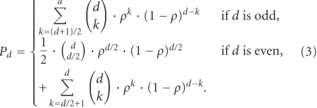
prob-ability that an incorrect path at distancedfrom the correct path is chosen by the Viterbi decoder. When hard-decision decoding is applied,Pdis given by (3), whereρis the
proba-bility of bit error for the modulation selected in the physical layer.3
Figure 2shows an example of the modifications made for
the SNR threshold in RBAR with and without the media-oriented mechanism. Commonly, a BER at the physical layer smaller than 10−5is considered acceptable in wireless LAN
applications. By using theoretical graphs of BER as function of the SNR for different transmission modes on a simple ad-ditive white Gaussian noise (AWGN) channel (seeFigure 2), we can compute the minimum SNR values required. Now, if a particular application can tolerate some bit errors (e.g., a BER up to the 10−3as shown inFigure 2), the receiver can
se-lect the highest rate for the following data transmission cor-responding to this SNR. For example inFigure 2, when the SNR is equal to 5 dB, the receiver can select a 9 Mbps data rate instead of a 6 Mbps data rate if it is aware that the appli-cation can tolerate a BER less than 10−3.
We have calculated the thresholds using (1), (2), and (3) for an application that can tolerate up to 10−3 BER (see
Table 2). The receiver can use arrays of thresholds that are
precomputed for different LTs.
In the following sections, we describe how such a mech-anism can be implemented in 802.11-based WLANs.
2We have used thea
dcoefficients provided in [21].
Bits 0–3 Bit 4 Bit 5 Bits 6-7 Bits 8–15
Traffic ID Schedule pending ACK policy Reserved TXOP duration
Figure3: QoS control field in the 802.11e.
Frame
Figure4: Modifications to the RTS header.
4.2. Implementation issues
We propose to implement MORSA with the help of the EDCA protocol [22,23]. EDCA is one of the features that has been proposed by IEEE 802.11e to support QoS in WLANs [9]. In this protocol, each QoS-enhanced station (QSTA) has 4 queues to support up to 8 user priorities (UPs). Figure 3
shows the QoS control field that is added to the MAC header in the 802.11e specification [9]. Bits 6 and 7 of this header can be used to indicate the loss tolerance information. Table 3
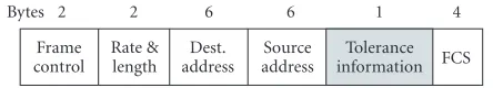
shows a possible meaning for these two bits in our media-oriented mechanism that should be defined in the process of connection setup. LT information is sent to the receiver by adding one byte to the RTS packets as illustrated in
Figure 4.
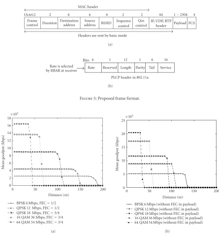
To make our mechanism operational, it is crucial to let the packets with corrupted payload reach the receiver’s ap-plication layer. As such, some modifications of the standard are necessary. First, the CRC at the MAC layer should no more cover the payload but only the MAC, IP, UDP, and possibly the RTP headers. Second, the optional UDP check-sum must be disabled, as described in the UDP lite pro-posal [24]. UDP lite is a lightweight version of UDP with increased flexibility in the form of a partial checksum. The coverage of the checksum is specified by the sending applica-tion on a per-packet basis. This protocol can be profitable for MORSA. Furthermore, to make our mechanism more robust against bit errors, the headers of the different layers (MAC, IP, UDP, and RTP) have to be sent with the basic rate
(see Figure 5). This is somewhat similar to the reservation
subheader used in [12] as explained inSection 2. The cor-responding bandwidth overhead is investigated in the next section.
5. SIMULATION RESULTS
Our simulations are based on the simulation environment described in [25] which uses the NS-2 network simulator, with extensions from the CMU Monarch Project [26] to sim-ulate multihop wireless ad hoc networks. In order to obtain more realistic results, Cisco Aironet 1200 Series parameters are used in our simulations [27]. Further details about the simulation environment are available in [25].
Note that in the following simulations, CTS and RTS control packets and PLCP headers are sent with a BPSK mod-ulation, an FEC rate equal to 1/2, and a 6 Mbps data rate. All throughputs shown in the following figures exclude the MAC and PHY headers; they are denoted as goodputs for the remainder of the paper.
To evaluate the perceived quality for the user using our protocol, we have taken an example of video application that can tolerate 0.1% of bit errors (seeSection 6.2). Thus, we have investigated the throughput performance of MORSA when the BER is equal to 10−3in the following simulations.
Of course other values of the BER can be chosen to perform simulations with similar results.
In our simulation, we assume that bit errors in a packet are distributed according to a binomial distribution. This is an acceptable assumption since the position of the bit errors are not taken into account by NS-2. InSection 6, we will pro-vide more precise models for the distribution of bit errors in our data stream. Letnrepresent the number of bit errors in a packet ofNbits, and letpbe the probability of bit error. The probability of having less thanLbit errors can be calculated by
We first evaluate our mechanism in a simple ad hoc net-work that contains two wireless stations. These wireless sta-tions communicate on a single channel. Station A is fixed and station B moves toward station A. Station B moves in 5 m increments over the range of mobility (0 m–200 m) and is held fixed for a 60stransmission of CBR data towards sta-tion A. In each step, 30 000 CBR packets of size 2304 bytes (including physical layer FEC) are sent.
Figure 6shows the mean goodput of this single CBR
con-nection between two wireless stations versus the distance be-tween them for different transmission modes with and with-out media-oriented mechanism.4
Since no payload FEC is used in our media-oriented pro-tocol, the mean goodput is increased significantly compared to the standard transmission modes. For example, we can ob-serve that the media-oriented mechanism achieves a 4 Mbps mean goodput improvement at the highest rate mode. How-ever, this has a cost in coverage range: in the same example, it is 50 meters less. It should be noted that if an application
Frame
control Duration
Destination address
Source address BSSID
Sequence control
Qos control
IP, UDP, RTP
header Payload FCS
Octet:2 2 6 6 6 2 2 44 1−2304 4
MAC header
Headers are sent by basic mode (a)
Rate Reserved Length Parity Tail Service
Bits: 4 1 12 1 6 16
Rate is selected by RBAR at receiver
PLCP header in 802.11a (b)
Figure5: Proposed frame format.
18 16 14 12 10 8 6 4 2 0
×103
0 50 100 150 200
BPSK 6 Mbps, FEC=1/2 QPSK 12 Mbps, FEC=1/2 QPSK 18 Mbps, FEC=3/4 16 QAM 36 Mbps, FEC=3/4 64 QAM 54 Mbps, FEC=3/4
M
ean
goodput
(kbps)
Distance (m)
(a)
25 20
15 10
5
0 ×103
0 50 100 150 200
BPSK 6 Mbps (without FEC in payload) QPSK 12 Mbps (without FEC in payload) QPSK 18 Mbps (without FEC in payload) 16 QAM 36 Mbps (without FEC in payload) 64 QAM 54 Mbps (without FEC in payload)
M
ean
goodput
(kbps)
Distance (m)
(b)
Figure6: (a) Mean goodput versus distance for standard transmission modes and (b) media-oriented with 0.1% bit errors.
can tolerate more bit errors, the coverage range will be larger than for the standard transmission modes [23].
We have also evaluated the extra bandwidth overhead of the modified frame format. This overhead is caused by hav-ing to send the MAC header at the basic mode and by the ad-ditional byte in the RTS packet.Figure 7compares the mean throughput for the traditional RBAR and for RBAR with the modified frame format. The worst-case overhead at the max-imum rate is about 1 Mbps, but the coverage range does not change much compared to the standard specification.
To evaluate the performance of RBAR under different mode selection mechanisms, we need to calculate arrays of
thresholds for each mechanism (seeSection 4).Table 2shows these threshold values for RBAR and MORSA.5These results
show that if we can tolerate loss, we will be able to send data with a higher rate.
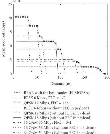
Figure 8 illustrates the performance of RBAR and
MORSA. Since the standard mode selection mechanism can achieve the maximum coverage range and the media-oriented mechanism obtains the maximum mean goodput,
18 16 14 12 10 8 6 4 2 0
×103
0 50 100 150 200
M
ean
goodput
(kbps)
Distance (m)
RBAR with standard transmission modes RBAR with new data frame format
Figure7: Overhead of the modified frame format.
25
20
15
10
5
0 ×103
0 50 100 150 200
M
ean
goodput
(kbps)
Distance (m)
RBAR with standard transmission modes RBAR with media-oriented (MORSA)
Figure 8: RBAR performance for standard and media-oriented protocols (MORSA).
we have defined a new media-oriented mode selection mechanism calledhybrid transmission mode selectionor H-MORSA, to achieve both objectives at the same time (see
Figure 9). The five PHY transmission modes that are used
for the hybrid mode selection mechanism do not use FEC. Then, we evaluate the two media-oriented mechanisms (MORSA and H-MORSA) in ad hoc networks. Figure 10
shows an example of network configuration for 20 nodes which are commonly used for ad hoc network evaluation [12, 26, 28].In our simulation, each ad hoc network con-sists of 20 mobile nodes that are distributed randomly in a 1500×300 meter arena. The speed at which nodes move is uniformly distributed between 0.9v and 1.1v, for different speeds ofv. We use the following speed values 2, 4, 6, 8, and 10 m/s. The nodes choose their path randomly according to
25 20 15
10
5
0 ×103
0 50 100 150 200
M
ean
goodput
(kbps)
Distance (m)
RBAR with the best modes (H-MORSA) BPSK 6 Mbps, FEC=1/2
QPSK 12 Mbps, FEC=1/2
BPSK 6 Mbps (without FEC in payload) QPSK 12 Mbps (without FEC in payload) QPSK 18 Mbps (without FEC in payload) 16 QAM 36 Mbps FEC=3/4
16 QAM 36 Mbps (without FEC in payload) 64 QAM 54 Mbps (without FEC in payload)
Figure 9: RBAR performance using standard or media-oriented protocol (H-MORSA).
Destination
Source 1500 m
300
m
Figure10: Example of ad hoc network topology scenario.
a random waypoint mobility pattern. The same movement patterns are used in all experiments whatever the mean node speed. For example, if node A moves from pointato point
b with a speed of 2 m/s, it will take the same route with 4, 6, 8, and 10 m/s in the other scenario patterns but with dif-ferent delays. All the results are based on an average over 30 simulations with 30 different scenario patterns.
600
Mean speed of nodes (m/s)
Media-oriented mode selection (MORSA)(0.1% LT) Hybrid mode selection (H-MORSA)
Standard mode selection (RBAR)
Figure11: Performance comparison for a single CBR connection in a multihop network, with and without MORSA.
1.4e+ 09 Standard mode selection (RBAR) Hybrid mode selection(H-MORSA) MORSA with 0.1% LT
Figure12: Number of delivered bits to the application (speed =
2 m/s).
routing protocol designed specifically for use in multihop ad hoc networks. It should be noted that routing packets are sent using the basic transmission mode like the RTS, CTS, and ACK control packets.
We use three automatic mode selection mechanisms de-fined in our previous simulations (see Figures8and9). In the standard mode selection mechanism (RBAR) and hy-brid mode selection mechanism (H-MORSA), we may have a hop in the route between source and destination that uses a physical FEC equal to 1/2. Thus, we have to use packets with a payload length equal to 1152 bytes for these simula-tions. However, with MORSA, we are able to send packets with 2304 bytes since no physical layer FEC is used in this mechanism.
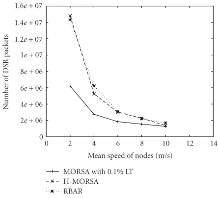
Mean speed of nodes (m/s) MORSA with 0.1% LT
H-MORSA RBAR
Figure13: DSR routing overhead in multihop network.
6e+ 06
Figure14: Performance comparison for a several CBR connection in multihop network, with and without media-oriented mecha-nism.
Figure 11shows the mean goodput of a single CBR
con-nection versus different mean node speeds. For an applica-tion that can tolerate a BER of 10−3, the mean goodput is
about 25% higher when we take into account the applica-tion’s characteristics.
Figure 12shows the number of delivered bits for 30
sce-nario patterns6with mean speed equal to 2 m/s. In the
sce-narios where the number of delivered bits is zero, DSR was not able to find a route between the source and the destina-tion during the whole simuladestina-tion time. As expected, in most
Temporal analysis
Spatial analysis
GOF i GOF i+1 Spatial
synthesis Motion
estimation
Motion compensated
prediction
GOF i GOF i+1 DFD
Rate control
VM JPEG-2000
VM JPEG-2000
Multiplex
Figure15: WAVIX structure.
45 40 35 30 25 20 15 10
0 50 100 150 200 250 300
PSNR
(dB)
Frame number Standard
Media-oriented (a)
16 14 12 10 8 6 4 2
0 500 1000 1500 2000
P
ack
et
tr
ansmission
time
(ms)
Packet number Standard
Media-oriented (b)
2.5 2 1.5 1 0.5 0
0 500 1000 1500 2000
Ji
tt
er
(ms)
Packet number Standard
Media-oriented (c)
45 40 35 30 25 20 15 10
0 50 100 150 200 250 300
PSNR
(dB)
Frame number Standard
Media-oriented (a)
10 9 8 7 6 5 4 3 2 1
0 500 1000 1500 2000
P
ack
et
tr
ansmission
time
(ms)
Packet number Standard
Media-oriented (b)
45 40 35 30 25 20 15 10
0 50 100 150 200 250 300
PSNR
(dB)
Frame number Standard
Media-oriented (c)
Figure17: PSNR, transmission delay, and jitter comparison (SNR=1.3 dB, 12 Mbps, FEC=1/2, QPSK).
of the scenario patterns, MORSA can deliver more data bits to the receiver. One interesting observation is that in some scenario patterns (less than 15% of them), the number of de-livered bits with the standard RBAR and H-MORSA is more than the one in MORSA. The rationale behind this is that DSR packets can be sent with the maximum coverage range in the standard and the hybrid mode selection mechanisms. As a result, the source can find a route to the destination faster than MORSA. Thus, the number of delivered packets in the standard RBAR and the H-MORSA is more than that of MORSA (e.g., scenario number 20).
We have also evaluated the overhead of the DSR routing protocol in different cases. The DSR algorithm has two dif-ferent phases calledroute discoveryandroute maintenanceto manage the routes in ad hoc networks. Inroute discovery, ad hoc nodes need to find a route between the source and the
destination. This is performed only when the source attempts to send a packet to the destination and does not already know a route. In route maintenance, DSR detects changes in the network topology such that the source can no longer use the current route to destination. This can occur if a link along the route is not usable anymore.
Figure 13shows the number of routing overhead packets
45 40 35 30 25 20 15 10
0 50 100 150 200 250 300
PSNR
(dB)
Frame number Standard
Media oriented (a)
5 4.5 4 3.5 3 2.5 2 1.5 1 0.5 0
0 500 1000 1500 2000
P
ack
et
tr
ansmission
time
(ms)
Packet number Standard
Media-oriented (b) 0.7
0.6 0.5 0.4 0.3 0.2 0.1 0
0 500 1000 1500 2000
Ji
tt
er
(ms)
Packet number Standard
Media-oriented (c)
Figure18: PSNR, transmission delay, and jitter comparison (SNR=8.5 dB, 36 Mbps, FEC=3/4, 16 QAM).
We have done different simulations to evaluate the per-formance of our mechanism in the presence of interference for ad hoc networks. For these simulations, 20 nodes are dis-tributed in an area of 500 ×100 meters which is 9 times smaller than previous simulation scenarios. In this simu-lation, 6 UDP connections are set up between 12 different nodes. Data is generated by CBR sources at a saturation rate. The first source starts data transmission at time 3 : 12 and the last one at 25 : 12. For this simulation, nodes are fixed and DSR does not need to useroute maintenance. The results are averaged over 30 different scenario patterns.
Figure 14 shows the performance of MORSA in these
ex-periments. Clearly, MORSA outperforms the standard mode selection (RBAR) and hybrid mode selection (H-MORSA) mechanisms. This is because the media-oriented mechanism considers the application’s characteristics and does not use FEC at the physical layer when the channel condition is good.
6. EVALUATION OF VIDEO QUALITY
Simulation results in NS-2 have shown a significant im-provement in throughput when considering the loss require-ments of the application to select the transmission mode. In this section, we evaluate the effectiveness of the proposed media-oriented mechanism using the simulation of a video transmission over a 802.11a wireless channel. Our previous observations about the performance of the media-oriented mechanism can be further justified by the evaluation of the video quality obtained at the receiver when we employ the media-oriented mechanism. In the following sections, we de-scribe a wireless channel model that can estimate the position and the length of burst error bits in 802.11a. Then, we present a video application that can tolerate a BER equal to 10−3
45 40 35 30 25 20 15 10
0 50 100 150 200 250 300
PSNR
(dB)
Frame number Standard
Media-oriented (a)
3.5 3 2.5 2 1.5 1 0.5 0
0 500 1000 1500 2000
P
ack
et
tr
ansmission
time
(ms)
Packet number Standard
Media-oriented (b) 0.5
0.45 0.4 0.35 0.3 0.25 0.2 0.15 0.1 0.05 0
0 500 1000 1500 2000
Ji
tt
er
(ms)
Packet number Standard
Media-oriented (c)
Figure19: PSNR, transmission delay, and jitter comparison (SNR=17.3 dB, 54 Mbps, FEC=3/4, 64 QAM).
6.1. 802.11a channel model
Wireless channel models can be divided into two main groups: memoryless models and models with memory. In memoryless models, corrupted bits are produced by a se-quence of independent trials. Each trial has the same probabilitypof producing a correct bit and probabilityq=
1−p of producing a bit error. However, in a real commu-nication environment, links have memory and errors often occur in isolated bursts because of multipath fading, impul-sive noise, or switch transients. A classic method to model a wireless channel with memory is using a Markov chain. In this model, the probability of bit error depends on the state of the model. We have considered in this section a model with memory, which is based on the model proposed in [29] for 802.11a WLANs.
In the 802.11a physical layer, the data field will be en-coded with a standard convolutional encoder of different
coding rateR=1/2, 2/3, or 3/4, depending on the data rate. The 1/2 convolutional encoder uses the generator polyno-mialsG0 =1338 andG1 =1718 and simple puncturing is applied to derive higher convolutional rates [30]. Regarding convolutional decoding, it is usually implemented using the Viterbi algorithm.
es-36
Figure20: 95% confidence intervals of PSNR for different trans-mission modes with media-oriented mode selection mechanism.
timate with classical techniques can be estimated with this method.
Then, we use the error event length distribution and the distribution of errorless periods to derive a simple model which describes the residual error at the output of the soft-decision Viterbi decoder. In the next section, we use this model to compute the distribution of corrupted bits for dif-ferent transmission modes.
6.2. Video encoder
The concept of fine-grain scalability (FGS) has been in-troduced in order to allow for dynamic rate adaptation to varying bandwidth and receiver capabilities. Compression solutions based on motion-compensated spatiotemporal sig-nal decomposition have thus gained attention as viable al-ternatives to classical predictive techniques for scalable video representation. The video codec that has been used in the ex-periments reported here, referred to as WAVIX in the sequel, has been developed in this framework.Figure 15shows the structure of WAVIX video encoder.
A group of frames (GOF) is fed into the coding system. In order to fine tune the bit rate allocated to the motion fields, the block-matching motion estimation makes use of a rate-constrained adaptive tree structure. The block size is thus adapted to local motion characteristics in a rate-distortion sense. The rate here refers to the bit rate allocated to encode the motion vectors and the distortion relates to the predic-tion error. The estimapredic-tion itself, to save computapredic-tion time, relies on a hierarchical approach. The motion vectors ob-tained in the first steps of the quadtree are used to initialize the search in the subsequent steps. The motion vectors are then predictively coded. The predictor is given by the me-dian value of neighboring vectors. The prediction error is then coded using Huffman codes.
The GOF is fed to the motion-compensated temporal transform which is based on a two-taps Haar wavelet trans-form. The temporal decomposition is applied iteratively on pairs of images within the GOF. The advantage of the Haar wavelet transform is to achieve a fairly good temporal energy compaction with a limited number of motion fields (8
mo-tion fields for a 3-stage temporal decomposimo-tion of a group of 8 images).Each temporal subband is then further decom-posed by a biorthogonal 9-7 wavelet filter in the horizontal and vertical direction. In the experiments, 3-levels decompo-sition are being used. The subbands resulting from the spa-tiotemporal decomposition are then quantized with a uni-form quantizer and encoded with a context-based bit-plane arithmetic coding as used in the JPEG-2000 standard [32]. The algorithm optimizing the truncation points in a rate-distortion sense handles groups of spatiotemporal subbands. The truncation point rate-distortion optimization leading to quality layers is well suited to fine tune the rate allocated to the texture information, hence to support fine-grain scalabil-ity.
An inter-GOF temporal prediction is also used as an op-tion in the above coding system. The inter-GOF temporal prediction leads to GOFs of type intra and of type inter. The inter-GOF temporal prediction requires one additional tion field. This temporal prediction and corresponding mo-tion estimamo-tion are realized in a closed loop. The closed-loop prediction is done by taking as reference information the cor-responding image coded at a lower rate, as used in a base layer of a scalable representation. A more detailed description of this video codec can be found in [33].
Arithmetic codes are widely used in coding systems due to their high compression efficiency. They are however very sensitive to bit errors. A single bit error may lead to a com-plete desynchronization of the decoder. In order to make the WAVIX codec robust to errors, an error-resilient arith-metic codes decoding technique [34] has been integrated in the video decoder. The technique consists in exploiting the residual redundancy in the bitstream by using soft-decision decoding procedures. The termsofthere means that the de-coder takes in input and supplies not only binary (hard) de-cisions but also a measure of confidence (a probability) on the bits. One can thus exploit the so-called excess rate (or sub-optimality of the code), to reduce the catastrophic de-synchronizationeffect of VLC decoders, hence to reduce the residual symbol error rates. This amounts to exploiting in-ner codeword redundancy as well as the remaining correla-tion within the sequence of symbols (remaining inter symbol dependency).
In practice, the decoding algorithm can be regarded as a soft-input soft-output sequential decoding technique run on a tree. The complexity of the underlying Bayesian esti-mation algorithm growing exponentially with the number of coded symbols, a simple, yet efficient, pruning method is in-tegrated. It allows the user to limit the complexity within a tractable and a realistic range, at a limited cost in terms of estimation accuracy.
In order to increase the resynchronization capability, a
soft synchronizationmechanism has been added. This mech-anism relies on both the use ofsoft synchronizationmarkers and of forbidden symbols. The soft synchronization mark-ers are patterns, inserted in the symbol stream at some known positions, which serve as anchors for favoring the likelihood of correctly synchronized decoding paths. This
(a) (b)
Figure21: A sample of video stream at the receiver, (a) transmitted by media-oriented algorithm with 0.1% bit errors (SNR=1.3, rate=
12 Mbps), (b) original video stream.
power of the chain at a controllable loss in information rate. The forbidden symbols, when used, provide additional error detection and correction capability [35].
The bitstream generated by WAVIX is split into mo-tion vectors and texture. The texture is encoded with the EBCOT algorithm. Hence, it has the same properties as a JPEG-2000 bitstream. The corresponding bitstream is sepa-rated into header and entropy-coded data. The header con-tains high-level information, like GOF sizes, and provides a description of the structure of the entropy-coded data. As this information is essential to the decoder, it is protected by a Reed-Solomon block code with high redundancy (e.g., 127/255).
6.3. Multimedia transmission over 802.11a wireless channel
In this section, we evaluate the quality of the video bitstream at the receiver side when the media-oriented mechanism is used. In our experiments, the WAVIX video encoder is con-figured to encode a sample of 300 CIF video frames. The video bit rate is 2 Mps and each frame is a YUV image.7The
number of frames in each GOF is 8. The activation of the WAVIX error resilience options corresponds to the addition of a 127/255 Reed-Solomon block code for header protection and of synchronization markers as explained inSection 6.2. The overhead of the header protection represents about 5.2% of the video stream while the overhead of the synchroniza-tion markers is negligible.
The transmission delay is calculated by considering the number of retransmissions and the value of the backofftimer [10]. The retransmission limit is defined in the IEEE 802.11 MAC standard specification with the help of the two follow-ing counters: the short retry count (SRC) and the long retry
7The foreman CIF (352×288 pixels) video sequence has been used.
count (LRC). These counters are incremented and reset in-dependently. The SRC is incremented every time an RTS fails and LRC is incremented when data transmission fails. Both the SRC and the LRC are reset to 0 after a successful data transmission. Data frames are discarded when SRC (LRC) reaches dot11ShortRetryLimit (dot11LongRetryLimit). The default values for dot11ShortRetryLimit and dot11Long-RetryLimit are 7 and 4, respectively.
Furthermore, we consider the backofftimer period af-ter each retransmission. For each retransmission, we select a random backoffwhich is drawn from a uniform distribu-tion over the interval [0, CW]. In each retransmission, CW is updated to either 2×(CW +1)−1 or its maximal value aCWmax. Let ¯Tbackoff(i) denote the average backoffinterval
af-tericonsecutive unsuccessful transmission attempts. It can be calculated by [36]
¯
Tbackoff(i)=
2iaCW
min+1
−1
2 ·aSlotTime, 0≤i≤6, aCWmax
2 ·aSlotTime, i≥6, (5) where aCWmin, aCWmax, and aSlotTime are 15, 1023, and
9 microseconds for IEEE 802.11a WLANs [30].
We have chosen 4 SNRs corresponding to 4 different transmission modes (seeTable 2). Using the 802.11a channel model described inSection 6.1, we can find the distribution of bit errors for each SNR and transmission mode at the out-put of Viterbi decoder. The bit errors are distributed over the packets of length 1000 bytes.
Table4: Transmission time comparison for video transmission with and without media-oriented mechanism.
Modulation Data rate (Mbps) FEC rate SNR (dB) Transmission duration Transmission duration
for standard (s) for media-oriented (s)
BPSK 6 1/2 −1.6 8.00 6.92
QPSK 12 1/2 1.3 4.14 3.57
16 QAM 36 3/4 8.5 1.09 0.96
64 QAM 54 3/4 17.3 0.81 0.72
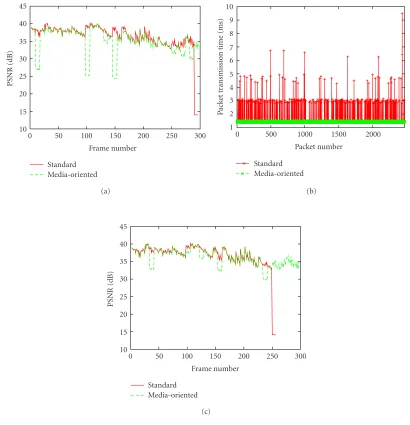
Figures 16, 17, 18, and 19 show the PSNR, sion delay, and interval jitter performance for 4 transmis-sion modes with both the standard and the media-oriented mechanisms.Table 4also shows the overall duration of the transmission for this video stream. As expected, the media-oriented mechanism (with LT = 0.1% and 5.2% FEC head at the application layer) significantly decreases the over-all duration of the transmission (seeTable 4).
We made the following observations from Figures16,17,
18, and 19. The packet transmission time is almost fixed with the media-oriented mechanism while it continuously changes with the number of retransmissions using the stan-dard mechanism. When the media-oriented mechanism is used, the PSNR of the decoded video is equivalent to the standard transmission mode, except for thedrops that cor-respond to GOFs where errors occur. In this case, error re-silience options allow us to decode the GOFs with the best achievable visual quality. The corrupted frames exhibit a lower quality, but their visual content is preserved. When the PSNR remains above 30 dB, the degradation is generally un-noticeable for a human viewer. When the PSNR falls as low as 25 dB, the decoded frames are severely degraded but are still acceptable by a human viewer. The impact of errors on the visual quality depends on the characteristics of the current frame (in particular, the number and positions of errors, and the video content). In applications involving real-time con-straints, as for instance visiophony or streaming, it may be preferable to receive a degraded frame rather than losing it entirely or slowing down the video playback because of pack-ets retransmission.
Another observation from the PSNR calculation is that after 4 consecutive retransmissions, (i.e., when a packet is lost for good), the standard transmission mechanism can-not decode the rest of the video frame (e.g., this occurs at the frame number 220 inFigure 16). However, this problem can be solved at the transmitter side with a more intelligent pack-etization scheme, or by adding resynchronization patterns within the data flow. Nonetheless, in case of packet drop, the visual content of a full GOF may be lost.
Figures16,17,18, and19also show the jitter for the stan-dard and the media-oriented mode selection mechanisms. First, it is obviously and logically correlated to transmission delay. In the media-oriented mechanism, the jitter is much less important than with the standard mode. This is a very desirable property in the case of video transmission. Having a constant time interval between packets arrivals is equivalent
to having a constant time slot available to decode each GOF. Therefore, complexity can be managed easily without the need for excessive buffering.
We have simulated the same scenarios for 10 diff er-ent channel characteristics (different distributions of cor-rupted bits over data flow) in order to calculate the confi-dence interval of the PSNR with the media-oriented trans-mission mode. For each transtrans-mission rate, the 95% confi-dence intervals on the mean PSNR are computed. The inter-vals for the various rates are displayed by horizontal lines as shown inFigure 20. The results show an acceptable PSNR in all transmission modes. Figure 21shows a sample of video stream transmitted with the media-oriented algorithm at 12 Mbps.
7. CONCLUSION
In this paper, we have presented a novel cross-layer mecha-nism in MANETs to select the best transmission mode which takes into account some characteristics of the application. This mechanism, which we believe to be easy to implement in actual devices, uses information from the physical chan-nel and the loss-tolerance requirements of the application to select the optimal PHY rate, modulation, and FEC trans-mission parameters. We have proposed new transtrans-mission modes which do not use FEC and which significantly increase the application throughput. NS-based simulation results in ad hoc networks show that our mechanism achieves up to 4 Mbps increase in throughput in MANETs. The gain ob-tained from the application point of view has been evaluated with the help of the WAVIX video encoder, which can toler-ate a BER equal to 10−3with only 5% of FEC overhead at the
application level. The results show significant improvements in throughput, latency, and jitter.
ACKNOWLEDGMENTS
REFERENCES
[1] S. Shakkottai, T. S. Rappaport, and P. C. Karlsson,
“Cross-layer design for wireless networks,” IEEE Commun. Mag.,
vol. 41, no. 10, pp. 74–80, 2003.
[2] S. Toumpis, “Capacity and cross-layer design of wireless Ad Hoc networks,” Ph.D. thesis, Department of Electrical En-gineering of Stanford University, Stanford, Calif, USA, July, 2003.
[3] A. Safwat, H. Hassanein, and H. Mouftah, “Optimal
cross-layer designs for energy-efficient wireless Ad Hoc and
sen-sor networks,” inProc. 22nd IEEE International Performance,
Computing, and Communications Conference (IPCCC ’03), pp. 123–128, Phoenix, Ariz, USA, April 2003.
[4] W. H. Yuen, H.-N. Lee, and T. D. Andersen, “A simple and ef-fective cross layer networking system for mobile Ad Hoc
net-works,” inProc. 13th IEEE International Symposium on
Per-sonal, Indoor and Mobile Radio Communications (PIMRC ’02), vol. 4, pp. 1952–1956, Lisbon, Portugal, September 2002. [5] G. Holland and N. Vaidya, “Analysis of TCP performance over
mobile Ad Hoc networks,”Wireless Networks, vol. 8, no. 2, pp.
275–288, 2002.
[6] J. Mitola, “The software radio architecture,”IEEE Commun.
Mag., vol. 33, no. 5, pp. 26–38, 1995.
[7] H. Jegou and C. Guillemot, “Source multiplexed codes for
error-prone channels,” inProc. IEEE International Conference
on Communications (ICC ’03), vol. 5, pp. 3604–3608, Anchor-age, Alaska, USA, May 2003.
[8] T. Guionnet, “Codage robuste par descriptions multiples pour transmission sans fil d’information multim´edia,” Ph.D. thesis, University of Rennes, Rennes Cedex, France, 2003.
[9] IEEE 802.11 WG, “Draft Supplement to STANDARD FOR Telecommunications and Information Exchange Between Systems-LAN/MAN Specific Requirements - Part 11: Wire-less Medium Access Control (MAC) and Physical Layer (PHY) specifications: Medium Access Control (MAC) Enhancements
for Quality of Service (QoS),”IEEE 802.11e/Draft 4.2,
Febru-ary 2003.
[10] IEEE 802.11 WG, “Wireless LAN Medium Access Control
(MAC) and Physical Layer (PHY) specifications,” Standard
Specification, IEEE, 1999.
[11] A. Kamerman and L. Monteban, “WaveLAN-II: a
highperfor-mance wireless LAN for the unlicensed band,”Bell Labs
Tech-nical Journal, vol. 2, no. 3, pp. 118–133, 1997.
[12] G. Holland, N. H. Vaidya, and P. Bahl, “A rate-adaptive MAC
protocol for multi-hop wireless networks,” inProc. ACM
In-ternational Conference on Mobile Computing and Networking (MobiCom ’01), pp. 236–251, Rome, Italy, July 2001. [13] D. Qiao, S. Choi, A. Jain, and K. G. Shin, “MiSer: an
opti-mal low-energy transmission strategy for IEEE 802.11 a/h,” inProc. ACM International Conference on Mobile Computing and Networking (Mobicom ’03), pp. 161–175, San Diego, Calif, USA, September 2003.
[14] V. Bhuvaneshwar, M. Krunz, and A. Muqattash, “CONSET: a cross-layer power aware protocol for mobile Ad Hoc
net-works,” inProc. IEEE International Conference on
Communi-cations (ICC ’04), pp. 4067–4071, Paris, France, June 2004. [15] U. C. Kozat, I. Koutsopoulos, and L. Tassiulas, “A
frame-work for cross-layer design of energy-efficient
communica-tion with QoS provisioning in multi-hop wireless networks,” inProc. 23rd IEEE Annual Joint Conference of Computer and Communications Societies (INFOCOM ’04), vol. 2, pp. 1446– 1456, Hong Kong, China, March 2004.
[16] S. Krishnamachari, M. VanderSchaar, S. Choi, and X. Xu, “Video streaming over wireless LANs: a cross-layer approach,” inProc. IEEE Packet Video 2003 (PV ’03), Nantes, France, April 2003.
[17] M. Conti, G. Maselli, G. Turi, and S. Giordano,
“Cross-layering in mobile Ad Hoc network design,”IEEE Computer,
vol. 37, no. 2, pp. 48–51, 2004.
[18] Y. Shan and A. Zakhor, “Cross layer techniques for adaptive
video streaming over wireless networks,” inProc. IEEE
In-ternational Conference on Multimedia and Expo (ICME ’02), vol. 1, pp. 277–280, Lausanne, Switzerland, August 2002. [19] H. Liu and M. El Zarki, “Adaptive source rate control for
real-time wireless video transmission,”Mobile Networks and
Ap-plications, vol. 3, no. 1, pp. 49–60, 1998.
[20] M. Pursley and D. Taipale, “Error probabilities for spread-spectrum packet radio with convolutional codes and Viterbi
decoding,”IEEE Trans. Commun., vol. 35, no. 1, pp. 1–12,
1987.
[21] P. Frenger, “Multi-rate codes and multicarrier modulation for future communication system,” Ph.D. thesis, Chalmers Uni-versity of Technology, Goteborg, Sweden, 1999.
[22] Q. Ni, L. Romdhani, and T. Turletti, “A Survey of QoS
en-hancements for IEEE 802.11 wireless LAN,”Journal of
Wire-less Communication and Mobile Computing, vol. 4, no. 5, pp. 547–566, 2004.
[23] M. H. Manshaei, T. Turletti, and M. Krunz, “A media-oriented transmission mode selection in 802.11 wireless LANs,” in
Proc. IEEE Wireless Communications and Networking Confer-ence (WCNC ’04), vol. 2, pp. 1228–1233, Atlanta, Ga, USA, March 2004.
[24] L. A. Larzon, M. Degermark, and S. Pink, “UDP lite for real time applications,” Tech. Rep. 1999-01, HP Laboratories Bris-tol, BrisBris-tol, UK, April 1999.
[25] M. H. Manshaei and T. Turletti, “Simulation-based
perfor-mance analysis of 802.11a wireless LAN,” inProc.
Interna-tional Symposium on Telecommunications (IST ’03), Isfahan, Iran, August 2003.
[26] “The Rice University Monarch Project, Mobile Networking
Architectures,”http://www.monarch.cs.rice.edu/.
[27] “Cisco Aironet 1200 Series Access Point Hardware Installation
Guide,” available inhttp://www.cisco.com.
[28] D. B. Johnson, D. A. Maltz, and J. Broch, “DSR: the dy-namic source routing protocol for multi-hop wireless Ad
Hoc networks,” in Ad Hoc Networking, C. E. Perkins, Ed.,
chapter 5, pp. 139–172, Addison-Wesley, Boston, Mass, USA, 2001.
[29] R. Khalili and K. Salamatian, “A new analytic approach to evaluation of packet error rate in wireless networks,” Research Report RP-LIP6-2004-10-50, LIP6-CNRS, October 2004. [30] IEEE 802.11 WGPart 11a, “Wireless LAN medium access
con-trol (MAC) and physical Layer (PHY) specifications,”
High-speed Physical Layer in the 5 GHz Band,Standard
Specifica-tion, IEEE, 1999.
[31] G. D. Forney Jr., “Convolutional codes II.
Maximum-likelihood decoding,”Information and Control, vol. 25, no. 3,
pp. 222–266, 1974.
[32] D. S. Taubman and M. W. Marcellin,JPEG2000:
Fundamen-tals, Standards and Practice, Kluwer Academic, Boston, Mass, USA, 2002.
[33] J. Vieron and C. Guillemot, “Low rate FGS video compres-sion based on motion-compensated spatio-temporal wavelet
analysis,” inInternational Conference on Visual
Communica-tion and Image Processing (VCIP ’03), Proc. SPIE, pp. 732–744, Lugano, Switzerland, July 2003.
[34] T. Guionnet and C. Guillemot, “Soft decoding and synchro-nization of arithmetic codes: application to image
trans-mission over noisy channels,”IEEE Trans. Image Processing,
vol. 12, no. 12, pp. 1599–1609, 2003.
detection,” inProc. Data Compression Conference (DCC ’98), pp. 339–348, Snowbird, Utah, USA, March–April 1998. [36] D. Qiao and S. Choi, “Goodput enhancement of IEEE 802.11a
wireless LAN via link adaptation,” inProc. IEEE International
Conference on Communications (ICC ’01), vol. 7, pp. 1995– 2000, Helsinki , Finland, June 2001.
Mohammad Hossein Manshaei received his B.S. degree in electrical engineering and his M.S. degree in communication en-gineering from the Isfahan University of Technology (IUT), Iran, in 1997 and 2000, respectively. He joined as a Research As-sistant at the Department of Electrical and Computer Engineering in IUT in July 2000. He received another M.S. degree in com-puter science from the University of Nice
Sophia Antipolis in 2002. He is currently pursuing his Ph.D. degree in computer science in the Plan`ete Group at INRIA Sophia Antipo-lis. His research interests include wireless networking and adaptive communication protocols.
Thierry Turletti received the M.S. (1990) and the Ph.D. (1995) degrees in computer science both from the University of Nice Sophia Antipolis, France. During his Ph.D. studies in the RODEO Group at INRIA Sophia Antipolis, he designed one of the first videoconferecening tool for the Inter-net. From 1995 to 1996, he was a Post-doctoral Fellow in the Telemedia, Networks, and Systems Group at Laboratory for
Com-puter Science (LCS), Massachusetts Institute of Technology (MIT). He is currently a full-time Researcher in the Plan`ete Group at IN-RIA Sophia Antipolis. His research interests include multimedia applications, multicast transmission, and wireless networking. He currently serves on the Editorial Board of Wireless Communica-tions and Mobile Computing.
Thomas Guionnet received the B.S. de-gree from the University of Newcastle upon Tyne, UK, in computer science, in 1997. He obtained the Engineer degree in com-puter science and image processing and the Ph.D. degree from the University of Rennes 1, France, respectively, in 1999 and 2003. He was a Research Engineer at INRIA from 2003 to 2004 and was involved in the French National Project RNRT VIP and in the