Scholarship@Western
Scholarship@Western
Electronic Thesis and Dissertation Repository
8-21-2015 12:00 AM
Elastic Highly Available Cloud Computing
Elastic Highly Available Cloud Computing
Hassan Hawilo
The University of Western Ontario
Supervisor
Prof. Abdallah Shami
The University of Western Ontario
Graduate Program in Electrical and Computer Engineering
A thesis submitted in partial fulfillment of the requirements for the degree in Master of Engineering Science
© Hassan Hawilo 2015
Follow this and additional works at: https://ir.lib.uwo.ca/etd
Part of the Computer Engineering Commons, and the Systems and Communications Commons
Recommended Citation Recommended Citation
Hawilo, Hassan, "Elastic Highly Available Cloud Computing" (2015). Electronic Thesis and Dissertation Repository. 3103.
https://ir.lib.uwo.ca/etd/3103
This Dissertation/Thesis is brought to you for free and open access by Scholarship@Western. It has been accepted for inclusion in Electronic Thesis and Dissertation Repository by an authorized administrator of
ELASTIC HIGHLY AVAILABLE CLOUD COMPUTING
(Thesis format: Integrated Article)
by
Hassan Hawilo
Graduate Program in Electrical & Computer Engineering
A thesis submitted in partial fulfillment of the requirements for the degree of
Master of Engineering Science
The School of Graduate and Postdoctoral Studies The University of Western Ontario
London, Ontario, Canada
Abstract
High availability and elasticity are two the cloud computing services technical features. Elasticity is a key feature of cloud computing where provisioning of resources is closely tied to the runtime demand. High availability assures that cloud applications are resilient to failures. Existing cloud solutions focus on providing both features at the level of the virtual resource through virtual machines by managing their restart, addition, and removal as needed. These existing solutions map applications to a specific design, which is not suitable for many applications especially virtualized telecommunication applications that are required to meet carrier grade standards. Carrier grade applications typically rely on the underlying platform to manage their availability by monitoring heartbeats, executing recoveries, and attempting repairs to bring the system back to normal. Migrating such applications to the cloud can be particularly challenging, especially if the elasticity policies target the application only, without considering the underlying platform contributing to its high availability (HA). In this thesis, a Network Function Virtualization (NFV) framework is introduced; the challenges and requirements of its use in mobile networks are discussed. In particular, an architecture for NFV framework entities in the virtual environment is proposed. In order to reduce signaling traffic congestion and achieve better performance, a criterion to bundle multiple functions of virtualized evolved packet-core in a single physical device or a group of adjacent devices is proposed. The analysis shows that the proposed grouping can reduce the network control traffic by 70 percent. Moreover, a comprehensive framework for the elasticity of highly available applications that considers the elastic deployment of the platform and the HA placement of the application’s components is proposed. The approach is applied to an internet protocol multimedia subsystem (IMS) application and demonstrate how, within a matter of seconds, the IMS application can be scaled up while maintaining its HA status.
Co-authorship statement
This thesis contains the following manuscripts that have been accepted and published.
1) H. Hawilo, A. Kanso, A. Shami, “Towards an Elasticity Framework for Legacy Highly Available Applications in the Cloud” 10th IEEE SERVICES 2015.
2) H. Hawilo, A. Shami, M. Mirahmadi, R. Asal, "NFV: state of the art, challenges, and implementation in next generation mobile networks (vEPC)," Network, IEEE , vol. 28, no.6, pp.18,26, Nov.-Dec. 2014.
The following coauthors provided experimental and technical support for the studies listed above:
A. Shami provided technical expertise, opinion and perspective, based on his expertise and experience as a professor. He contributed to the work done in Chapter 2 and 3.
A. Kanso provided technical expertise, opinion and perspective, based on his expertise and experience as a researcher at Ericsson Company. He contributed to the work done in Chapter 3.
M. Mirahmadi provided technical expertise, opinion and perspective, based on his expertise and experience as a researcher at IBM Company. He contributed to the work done in Chapter 2.
Acknowledgments
This thesis is the result of a hard work and very busy research program, which would not have been possible without the support of a many of people.
I am very thankful to Prof. A. Shami, who provided thorough and helpful support with a close guidance throughout my masters’ research program. He has been my supervisor and friend.
I am very thankful to Dr. A. Kanso for providing his expertise that was essential for the success of this work. He always made sure to have a close consultation and support throughout my masters’ research program.
Many thanks to my friends and colleagues for the words of support and help during my masters’ research program.
To my family, particularly my parents, thank you for your love, support, and unwavering belief in me. Without you, I would not be the person I am today.
Above all, I would like to thank my wife Manar Jammal for her love and constant support, for all the late nights and early mornings, and for keeping me sane over the past few months (years) . Thank you for being my muse, editor, proofreader, and sounding board, but most of all, thank you for being my best friend.
Table
of
Contents
Abstract ... i
Co-authorship statement ... ii
Acknowledgments ... iii
List of Figures ... viii
List of Tables ... x
List of Abbreviations ... xi
Chapter 1 ... 1
1. Introduction ... 1
1.1 High Availability ... 1
1.1.1 Mean Time to Failure (MTTF) ... 2
1.1.2 Mean Time to Repair (MTTR) ... 3
1.1.3 Mean Time Between Failures (MTBF) ... 3
1.2 Achieving High Availability ... 4
1.2.1 Fault Tolerance ... 4
1.2.2 Redundancy... 5
1.2.3 Logical Entities of Highly Available System ... 6
1.2.4 Redundancy Models by SAForum: ... 7
1.2.4.1 2N Redundancy Model ... 7
1.2.4.2 N+M Redundancy Model ... 8
1.2.4.3 N-way Redundancy Model ... 9
1.2.4.4 N-Way Active Redundancy Model ... 10
1.2.4.5 No-Redundancy Redundancy Model ... 10
1.3 HA with Virtualization ... 11
1.5 Problem Formulation ... 13
1.6 Research Contributions ... 14
Bibliography ... 15
Chapter 2 ... 18
2. NFV: State of the Art, Challenges and Implementation in Next Generation Mobile Networks (vEPC) ... 18
2.1 Introduction ... 18
2.2 Network Function Virtualization ... 19
2.2.1 Openness of Platforms ... 20
2.2.2 Scalability and Flexibility ... 21
2.2.3 Operation Performance Improvement ... 21
2.2.4 Improve Development Cycle ... 22
2.2.5 Reduced CAPEX and OPEX ... 22
2.3 NFV and SDN ... 23
2.4 NFV Framework ... 24
2.5 Proposed Placement of Framework Entities ... 27
2.6 NFV Ecosystem ... 29
2.7 NFV Challenges and Requirements ... 29
2.7.1 Security ... 29
2.7.2 Computing Performance ... 30
2.7.3 Interconnection of VNFs ... 31
2.7.4 Portability ... 32
2.7.5 Operation and Management ... 32
2.7.6 Co-existence with Legacy Networks ... 33
2.7.7 Carrier-Grade Service Assurance ... 33
2.8.1 NFVI as a Service (NFVIaas) ... 35
2.8.2 VNF as a Service (VNFaaS) ... 35
2.8.3 Virtual Network Platform as a Service (VNPaaS) ... 35
2.8.4 Fixed Access Network Functions Virtualization ... 36
2.8.5 Content Delivery Networks Virtualization ... 36
2.8.6 Home Environment Virtualization ... 37
2.8.7 Mobile Network Virtualization ... 37
2.9 Virtualization of the Evolved Packet Core (EPC) ... 38
2.10 Grouping EPC Entities in the NFV Environment ... 39
2.10.1 Segment One ... 40
2.10.2 Segment Two ... 41
2.10.3 Segment Three ... 42
2.10.4 Segment Four ... 42
2.11 Quantitative Analysis ... 44
2.12 Chapter Contribution ... 47
Bibliography ... 47
Chapter 3 ... 51
3. Towards an Elasticity Framework for Legacy Highly Available Applications in the Cloud ... 51
3.1 Introduction ... 51
3.2 High Availability Middleware and Scheduling ... 54
3.2.1 OpenSAF Cluster ... 56
3.2.2 High Availability Scheduling ... 58
3.3 Elasticity Framework ... 58
3.3.1 Application Design and Elasticity Requirement Specification ... 59
3.3.2.1 Identifying the Constraints ... 61
3.3.2.2 Maximizing the Availability of the Application ... 63
3.3.2.3 Optimizing the Placement for Performance and Other Factors .. 63
3.3.3 Automated Elastic Multi-Level Deployment ... 65
3.3.3.1 Infrastructure Elasticity ... 65
3.3.3.2 Platform Elasticity ... 66
3.3.3.3 Application Elasticity ... 67
3.4 Framework Workflow and Implementation ... 68
3.5 Test-bed and Case Study ... 69
3.6 Literature Review... 72
3.7 Chapter Contribution ... 74
Bibliography ... 74
Chapter 4 ... 79
4. Conclusion and Future Work ... 79
4.1 Conclusion ... 79
4.2 Future Work ... 80
List of Figures
Fig. 1.1 Maximum allowable downtime for different availability levels [1]. ... 2
Fig. 1.2 Availability in terms of MTTF, MTTR, and MTBF ... 2
Fig. 1.3 MTTR, MTTF, MTBF [1]. ... 3
Fig. 1.4 2N redundancy model [6]. ... 7
Fig. 1.5 N+1 Redundancy Model [6]. ... 8
Fig. 1.6 N-way redundancy model [6]. ... 9
Fig. 1.7 N-way active redundancy model [6]. ... 10
Fig. 1.8 Vertical Scaling vs Horizontal Scaling. ... 13
Fig. 2.1 Network function virtualization concept. ... 20
Fig. 2.2 Service provider revenues vs traffic [2]. ... 23
Fig. 2.3 NFV differs from SDN. ... 24
Fig. 2.4 Virtualization Layout ... 25
Fig. 2.5 The cloud services ... 26
Fig. 2.6 NFV framework ... 27
Fig. 2.7 NFV Framework Entities Proposed Placements. ... 28
Fig. 2.8 Networking in virtualization environment. ... 31
Fig. 2.9 Base station virtualization evolution. ... 38
Fig. 2.10 vEPC Entities Grouping. ... 41
Fig. 3.1 The different perspectives of the cloud levels. ... 52
Fig. 3.2 Application components deployed in different datacenters. ... 53
Fig. 3.3 Overview of the elasticity framework. ... 59
Fig. 3.4 Snapshot of the application description interface. ... 60
Fig. 3.5 The cloud infrastructure hierarchical overview. ... 61
Fig. 3.6 The orbital distance of a given component. ... 62
Fig. 3.7 HA elastic scheduling algorithm. ... 64
Fig. 3.8 Elasticity framework workflow. ... 68
Fig. 3.9 Installation duration results. ... 71
List of Tables
Table 2.1 NFV challenges and solutions. ... 34
Table 2.2 Grouping of EPC entities in NFV environment. ... 44
Table 2.3 Signaling traffic before and after grouping. ... 46
List of Abbreviations
AIS Application Interface Specification
AMF Availability Management Framework
API Application Program Interface
ATCA Advanced Telecommunications Computing Architecture
CAPEX Capital Expenditure
CDN Content Distribution Network
CMS Configuration Management System
COTS Commercial-of-the-Shelf
CPU Central Processing Unit
CSCF Call Session Control Function
CSI Component Service Instance
DC Data Center
DevOps Development and Operations
DPDK Data Plane Development Kit
DPI Deep Packet Investigation
EMS Element management System
ETSI European Telecommunications Standards Institute
GPRS General Packet Radio Service
GSM Global System for Mobile Communications
GTP GPRS Tunneling Protocol
HA High Availability
HSS Home Subscriber Server
IaaS Infrastructure as a Service
ICT Information and Communication Technology
IMM Information Model Management
IMS IP multi-media Subsystem
Inc. Incorporation
IPSec Internet Protocol Security
IPTV Internet Protocol Television
IT Information Technology
LAN Local Area Network
LDAP Lightweight Directory Access Protocol
LTE Long-Term Evolution
M2M Machine-to-Machine
MAC Media Access Control
MDS Message Distribution system
MME Mobility Management Entity
MTBF Mean Time Between Failure
MTTF Mean Time to Fail
MTTR Mean Time to Repair
NaaS Network as a Service
NFV Network Function Virtualization
NFVI Network Function Virtualization Infrastructure
NIC Network Interface Controller
OCS Online Charging System
OPEX Operational Expenditure
OS Operating System
PaaS Platform as a Service
PCRF Policy and Charging Rules Function
PDCP Packet Data Convergence Protocol
PGW Packet Gateway
QoE Quality of Experience
QoS Quality of Service
RLC Radio Link Control
SaaS Software as a Service
SAForum Service Availability Forum
SCTP Stream Control Transmission Protocol
SDN Software Defined Networking
SG Service Group
SGSN Serving GPRS Support Node
SGW Serving Gateway
SI Service Instance
SMF Software Management Framework
SR-IoV Single Root I/O Virtualization
SU Service Unit
TCP Transmission Control Protocol
TLS Transport Layer Security
UDR Unified Data Repository
UE User Equipment
vEPC Virtualized Evolved Packet Core
VM Virtual Machine
Chapter 1
1. Introduction
With the rapid increase in the number of smart connected devices such as smart phone, tablets and wireless sensors, our society is greatly dependent on computer-based systems. These systems provide services that shaped our communities and how we interact in different field such as healthcare, financial services, and social networks. The need for providing these services continuously to the users is very critical in today’s society. Moreover, users are expecting and eager to have these service accessible anytime and anywhere. In order to provide such services upon which people can rely, application service designers must have a clear view of all the potential causes that may bring down a system and the possible solutions to address these challenges. In particular, the costs of such solutions in terms of computing resources requirements must be known. Users Dependability on a service defines its quality of service attributes such as reliability and availability. For instance, reliability is defined as time to fail from an initial referenced instant, whereas availability is the probability of obtaining a service at an instance of time. Such services require complex computer systems with high level of availability, typically 99.999% (five nines) of the time, which amounts to slightly over five minutes of downtime over a year time interval of continuous operation. This poses a significant challenges on service provides that need to minimize the capital and operational investment expenditures in order to increase their return-on investments.
1.1
High Availability
continuous operation. Fig.1.1. illustrates the maximum allowable downtime of a system against of availability nines.
Fig. 1.1 Maximum allowable downtime for different availability levels [1].
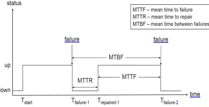
Availability is expressed as a probability representing the portion of which the system is healthy and can deliver its services as intended. Availability can be expressed by the mean time to failure (MTTF) and mean time to repair (MTTR) as shown in Fig.1.2.
Fig. 1.2 Availability in terms of MTTF, MTTR, and MTBF
1.1.1
Mean Time to Failure (MTTF)
1.1.2
Mean Time to Repair (MTTR)
MTTR attribute is defined as the expected time for the system to recover from a failure and return to a healthy state. It is also referred to as the downtime of a system in which it is neither operating nor providing a service.
1.1.3
Mean Time Between Failures (MTBF)
MTBF attribute is defined as the expected time for the system to have two consecutive failures. It is only defined in repairable systems.
Fig.1.3 illustrates MTTF, MTTR, and MTBF.
Fig. 1.3 MTTR, MTTF, MTBF [1].
In order to relate availability to the service time of a service, it can be expressed in terms of service uptime and service outage as follows:
1.2
Achieving High Availability
High availability of an application can be achieved by a set of fault tolerance practices and protective redundancy of application components. HA is not about preventing failures of application component from happening but minimizing recovery time of component failures to assure overall service continuity [2].
1.2.1
Fault Tolerance
Fault tolerance is a failure avoidance approach aiming to mediate and wrap faults from causing service failure. Despite all the fault prevention methods employed by the application developer, there still a probability that a fault can cause a system failure. The main objective of fault tolerance is to ensure that a system can tolerate the possibility of fault occurrence by applying error detection and system component recovery. It can detect and handle faults before causing application service failure. Fault tolerance is considered to manage recovery of unplanned events and outages of the underlying system. The four major faults tolerance phases for achieving service availability [3] are:
1) Error Detection: to successfully sustain a highly available system, the fault occurrence must be first identified.
2) Damage Confinement and Assessment: the failure damage level is evaluated and restrained as much as possible. System state information is communicated between components to limit the scope and propagation of the error.
3) Error Recovery: is the process of eliminating the system failure cause and transforming the system to a healthy state.
4) Fault Treatment and Service Continuation: The key concern in this process is the perception to users that the intended service continues to be functioning as if nothing has happened.
failure response shapes how it reacts when a failure is encountered. The system failure response can be defined as follow:
1) Fail-Operational: The service operates normally in the presence of faults with no degradation of service functionality and performance. This type of failure response assures the highest level of service availability but on the expense of additional system resources to cover all the conceivable failures.
2) Fail-Soft (graceful degradation): The service operates in a degraded functionality and performance. The main objective of this system failure response type is keeping the mission critical functionality of the system functioning normally. 3) Fail-Safe: The service maintains it functionalities for the current operation and
halts its intended operation. This type of system failure response mainly used to secure safe condition for the users being served.
4) Fail-Stop: The service is immediately stop when an error is detected. This type of system failure response also known as Fail-Fast response. It used in situation where error propagation is suspected.
1.2.2
Redundancy
The major fault tolerance approach is to have a redundancy system components protection. Redundant system components translate into additional resources held at idle state in a normal operation of the system. The replicated system components protect the service from potential failures, giving the feel of uninterrupted service even when there are failures in the underlying system. The main two aspect related to redundancy that system designers and administrator must consider are (1) what should be replicated; and (2) in what state these replica stand to achieve the desired service availability.
recently with one of the pioneer information technology (IT) companies; Apple incorporated (Inc.). March 11, 2015, Apple store experienced a complete outage for eleven hours [4]. This outage was caused by a release of faulty update that propagated along all their system components [5]. The best practice of redundant system components protection is applying a redundancy model based on the functionality of the system component. It is necessary to differentiate the role that each system component entitles. A component is considered to have an active role if it is serving current users. The redundant component takes the standby role if it is capable to take over the active role and sustains the service provided by the system. The active and standby components must communicate health conditions to successfully failover the workload up on fault occurrence. Service availability forum defined five types of redundancy models in the SAForum specifications [6].
1.2.3
Logical Entities of Highly Available System
Service availability forum (SAForum) defined the availability management framework (AMF) logical entities as follow [6]:
1) AMF Node: is also a logical entity where the HA middleware and HA application component are executed. The AMF manages its different states and defines its operations.
2) Component: is the logical entity that represents a set of resources to the AMF. It encapsulates specific application functionality. The resources can be a set of hardware resources, software resources, or a combination of the two. In addition, it presents the smallest logical entity on which the AMF performs error detection and isolation, recovery, and repair.
3) Component Service Instance (CSI): represents the workload that the AMF can dynamically assign to a component. High availability (HA) states are assigned to a component on behalf of its component service instances.
present the unit of redundancy from the AMF perspective. It is the smallest logical entity that can be instantiated in a redundancy manner.
5) Service Instances (SI): is aggregated CSIs in one logical entity. AMF assigns the SIs as workload to the SUs.
6) Service Group (SG): is a logical entity combining one or more SUs to form a protective group for a specific service.
1.2.4
Redundancy Models by SAForum:
The redundancy models defined the layout of the components states such as active and standby.
1.2.4.1
2N Redundancy Model
In a 2N redundancy model, at most one SU has the active HA state for all the workloads assigned as SIs. In addition, only one SU has the standby HA state for all the workloads assigned as SIs. Other SUs in the SG are configured to be spare units.
1.2.4.2
N+M Redundancy Model
The N+M redundancy model is an extension to the 2N redundancy model by permitting two or more SUs to have active and standby HA states. N presents the number of SUs having the active HA state. M presents the number of SUs having the standby HA state. This redundancy model mandates that the SU can have a strict HA state. For instance if one SU is assigned active HA state for a particular SI, it cannot be assigned standby HA state for another SI. The most common N+M redundancy model is N+1. Fig. 1.5 illustrates the N+1 redundancy model.
1.2.4.3
N-way Redundancy Model
The N-way redundancy model slightly differs from the N+M redundancy Model. It allows the SUs to have simultaneously active and standby assignments for different SIs. The advantage of this redundancy model is that all SUs can have active HA state while providing protection standby HA state.
1.2.4.4
N-Way Active Redundancy Model
The N-way active redundancy model differs from the previous redundancy models, as it does not support standby HA state. It allows the SI to have a several active SUs.
Fig. 1.7 N-way active redundancy model [6].
1.2.4.5
No-Redundancy Redundancy Model
1.3
HA with Virtualization
Could computing is the paradigm of providing data, software and hardware services on-demand through different means of connectivity [7]. Mainly cloud computing utilizes various virtualization technologies to provide its services. Datacenters packing large number of servers, are the core engines of cloud computing that provide the main resource pools for many information and communication technology (ICT) companies. ICT companies rent cloud resources to provide their own distinct services ranging from business-critical processes and scientific computing [8], to social networking [9] and online gaming [10][11]. With large scale datacenters infrastructure composed from wide range of devices, resource failures are expected to happen [12][13]. Failures occurring during peak service periods, such as flashcrowds [14][15], and just before the outcome of specific application results are generated, leads to a significant low quality of experience (QoE). This low QoE results in revenue losses or customer departure [16].
1.4
Elasticity in Cloud
Elasticity is one of the core attributes of cloud computing paradigm. The elasticity term is heavily used by the cloud providers’ advertisements as a functionality to enhance cloud hosted application workload response.
Elasticity is the ability of a system to adapt its resources according to changes in the workload in an autonomic manner, such that the available resources are provisioned and released to match the current demand in real-time. Elasticity differs from scalability of the system where resources have the ability to be increased but not meant to match the workload [22]. To achieve elasticity in cloud different aspects have to be considered.
1) Automated Up and Down Scaling Configuration:
Elasticity of resource is meant to match the workload in real-time. To provide the real-time aspect of elasticity the scaling process must assure no manual configuration is involved in the process.
2) Elasticity Dimensions:
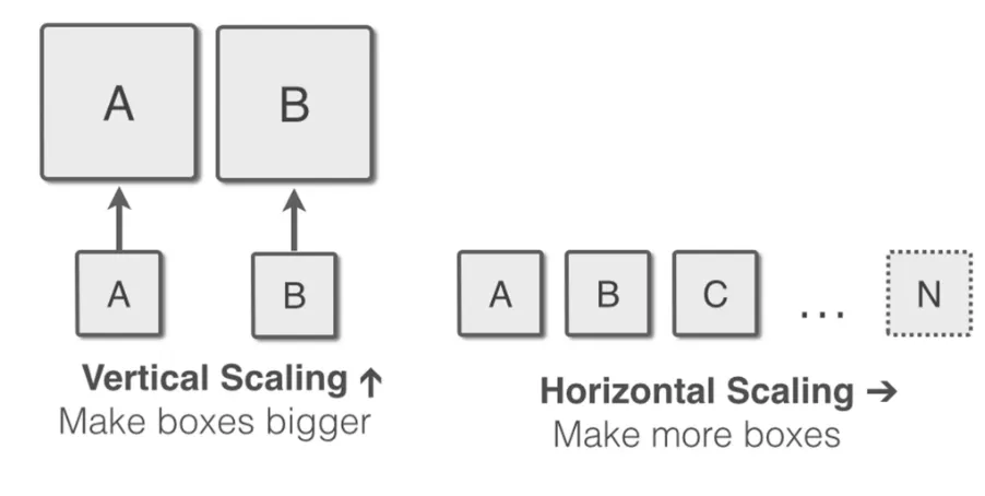
Application service consists of various tiers (1) application software tier (2) application middleware tier (3) system resources tier. Scaling of an application should be defined according which tiers it should scale. For instance, an application can be scaled on the resources tier while maintaining the same number of software instance. This kind of scaling is known as vertical resource scaling 3) Scalability Bounds:
Fig. 1.8 Vertical Scaling vs Horizontal Scaling.
1.5
Problem Formulation
and pay-as-you-go services. Therefore, in order to prepare the cloud to meet the requirements of carrier grade applications, we conducted a research to investigate and provide a solution that satisfies these requirements without sacrificing the advantages of the cloud-computing era.
1.6
Research Contributions
The work described in the subsequent chapters introduces several research contributions.
In particular:
1) Chapter 2 defines various challenges that encounter the NFV application development and deployment along with a set of practices and solutions for these challenges.
2) Chapter 2 proposes a placement for the ETSI NFV framework’s entities in the current cloud computing stack.
3) Chapter 2 defines a grouping criterion for the virtualized evolved packet core (vEPC) entities. The entities’ grouping criterion is conducted to suit vEPC for cloud deployment while maximizing performance and minimizing the signaling traffic between its entities.
4) Chapter 3 defines an elasticity framework for highly available application in cloud. This framework migrates the SAForum specification to the cloud environment to satisfy the carrier grade requirements.
5) Chapter 3 presents the implemented prototype of the framework using various technologies such as DevOps tools and proprietary developed software.
Bibliography
[1] Service Availability Forum, “Application Interface Specification,” http://devel.opensaf.org / SAI-Overview -B.05.03.AL.pdf, 2011.
[2] P. S. Weygant “Clusters for High Availability: A Primer of HP Solutions,” Prentice Hall PTR, Upper Saddle River, NJ, USA, 2001.
[3] P. A. Lee, T. Anderson “Fault Tolerance: Principles and Practice,” Springer-Verlag New York, Inc., Secaucus, NJ, USA, 1990.
[4] CNBC,”http://www.cnbc.com/2015/03/11/some-apple-services-suffering-outages.ht ml,” 2015.
[5] Apple, “http://appleinsider.com/articles/15/03/11/apple-issues-apology-as-itunes-app-store-outage-persists-for-7-hours,” 2015.
[6] Service Availability Forum, “Availability Management Framework,” http://devel.opensaf.org/SAI-AIS-AMF-B.04.01.AL.pdf, 2011.
[7] M.A. Sharkh, M. Jammal, A. Shami, A. Ouda, “Resource allocation in a network-based cloud computing environment: design challenges”, IEEE Communications Magazine, vol. 51, no. 11, pp. 46–52, November 2013.
[8] D. Talia, “Clouds for scalable big data analytics.” IEEE Computer, vol. 46, no. 5, 2013.
[9] Y. Chen, S. Alspaugh, R. H. Katz, “Interactive analytical processing in big data systems: A cross-industry study of mapreduce workloads,” PVLDB, vol. 5, no. 12, 2012.
[11] V. Nae, A. Iosup, R. Prodan, “Dynamic resource provisioning in massively multiplayer online games,” TPDS, vol. 22, no. 3, 2011.
[12] F. Cappello, A. Geist, B. Gropp, L. V. Kale´, B. Kramer, M. Snir, “Toward exascale resilience,” IJHPCA, 2009.
[13] B. Schroeder, E. Pinheiro, W.-D. Weber, “DRAM errors in the wild: a large-scale field study,” in SIGMETRICS, 2009.
[14] I. Ari, B. Hong, E. L. Miller, S. A. Brandt, D. D. E. Long, “Managing flash crowds on the internet,” in MASCOTS, 2003.
[15] P. Bod´ık, A. Fox, M. J. Franklin, M. I. Jordan, D. A. Patterson, “Characterizing, modeling, and generating workload spikes for stateful services,” in SoCC, 2010.
[16] B. Javadi, D. Kondo, A. Iosup, D. H. J. Epema, “The failure trace archive: Enabling the comparison of failure measurements and models of distributed systems,” JPDC, vol. 73, no. 8, 2013.
[17] VMWare Inc., “Protecting Mission-Critical Workloads with VMware Fault Tolerance,”www.vmware.com/files/pdf/ resources/ft_virtualization_wp.pdf, 2009.
[18] Amazon, “Building Fault-Tolerant Applications on AWS,”
http://media.amazonwebservices.com/AWS_Building_Fault_Tolerant_Applications. pdf, 2011.
[19] Google, “Google Cloud SQL now Generally Available with an SLA, 500GB databases, and encryption,” http://googlecloudplatform.blogspot .ca/2014/02/googlecloud-sql-now-generally-available.html, 2014.
[21] CDNetworks,” How Much is Each Second Worth in Ecommerce?,” http://www.cdnetworks.com/blog/how-much-is-each-second-worth-in-ecommerce-check-out-these-15-stats/, 2013.
Chapter 2
2. NFV: State of the Art, Challenges and Implementation in
Next Generation Mobile Networks (vEPC)
As mobile network users look forward to the connectivity speeds of 5G networks, network providers are facing challenges in complying with projected demands without substantial financial investments. Network function virtualization (NFV) is introduced as a new methodology that offers a way out of these bottlenecks. NFV is poised to change the core structure of telecommunications infrastructure to be more cost-efficient. In this chapter, Network Function Virtualization (NFV) is introduced with a discussion about the challenges and requirements of its use in mobile networks. In particular, an architecture for NFV framework entities in the virtual environment is proposed. Moreover, in order to reduce signaling traffic congestion and obtain better performance, this chapter proposes to bundle multiple functions of virtualized evolved packet-core in a single physical device or a group of adjacent devices.
2.1 Introduction
The demand for reducing capital expenditures (CAPEX) and operating expenditures (OPEX) has pushed information technology (IT) specialists toward contemplating designs to achieve more effective capital investments with higher return on capital. Toward this goal, the virtualization technology has emerged as a way to decouple software applications from the underlying hardware and enable software to run in a virtualized environment. In a virtual environment, hardware is emulated, and the operating system (OS) runs over the emulated hardware as if it is running on its own bare-metal resources. Using this procedure, multiple virtual machines can share available resources and run simultaneously on a single physical machine [1].
is pushing network service providers to invest in their infrastructure to keep up with the demand, although studies show that the return on such investments is minimal [2]. Network expenditures depend highly on the infrastructure on which the network relies. The high cost of any network-improvement upgrade or new service release narrows the revenue margin of the service provider. Network operating challenges are not limited to the cost of expensive hardware devices, but also include increasing energy costs and the competitive market for highly qualified personnel with the skills necessary to design, integrate, and operate an increasingly complex hardware-based infrastructure. In addition, managing network infrastructure is another major concern of service providers. These issues do not affect revenue only, but they also increase time-to-market and limit innovation in the telecommunications industry. Therefore, network operators seek to minimize or even eliminate their dependency on proprietary hardware.
To achieve these targets successfully, a group of seven telecom operators has formed an industry specifications group for Network Function Virtualization (NFV) under the European Telecommunications Standards Institute (ETSI). They revealed their solution in October 2012 [3]. More recently, several telecom-equipment providers and IT specialists joined the group.
2.2
Network Function Virtualization
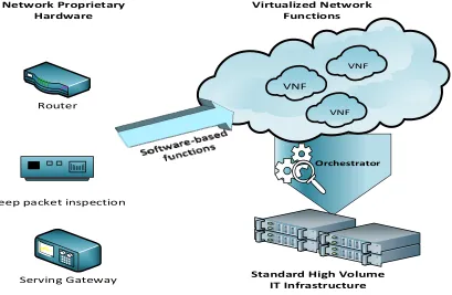
These applications are executed and consolidated on standard IT platforms like high-volume servers, switches, and storage. Through NFV, network functions can be instantiated in various locations such as datacenters, network nodes, and end-user premises as the network requires [3]. Fig 2.1 illustrates the migration of network proprietary hardware to a software-based application on COTS equipment.
Router
Deep packet inspection
Serving Gateway
Network Proprietary
Hardware
VNF
VNF VNF Virtualized Network
Functions
Orchestrator
Standard High Volume
IT Infrastructure
Fig. 2.1 Network function virtualization concept.
NFV is poised revolutionize the telecommunication era from research to industrial implementations. Telecommunication equipment vendors have to reform their doctrine to compete in the new software based telecommunication area. NFV has been foreseen to lead the future of telecommunication. As NFV decouple the network functions from underlying hardware, it offers many benefits to the telecommunication systems. Some of these benefits are listed below.
2.2.1
Openness of Platforms
embrace a standardized form for the interfaces and the network functions themselves. By such act, service providers could avoid the vendor lock-in in their network equipment that have sustained for years. Vendor Locked-in has overwhelmed their budgets, and degraded their network performance. Adopting openness concept assures that service providers benefit from multi-vendor network functions that serve their needs [4]. They merge all the expertise from different vendors since there is no single vendor who masters all the network functionalities. Furthermore, openness of the platforms would facilitate new revenue trends and opportunities for better contribution and innovation from IT and software designing companies, startup companies and academia. Also open source projects could be initiated to improve network functions performance [3].
2.2.2
Scalability and Flexibility
Telecommunication service providers design their networks infrastructure according to network traffic demand in the peak hours to be able to handle that traffic and maintain their targeted quality of service (QoS). Most of the time these equipment would not be efficiently utilized and yet they have to be managed and maintained functional 24/7 to provide the services. Furthermore, proprietary telecommunication equipment occupies space and consumes energy to operate and maintain the functional terms, e.g., temperature of the equipment. NFV addresses these concerns and allow service providers to easily scale their infrastructure in real-time since they are deployed in virtualized environment [5]. Virtualized network functions (VNFs) are dynamically scaled to fulfill the traffic demands. VNFs resources could be scaled up in specific locations where higher demands are needed. NFV also allows resources sharing between lightly utilized VNF and higher demanded VNFs. However, service providers will benefit from downscaling their VNF resources during off peak hours. This down scaling allows service providers to benefit from assigning these resources to serve other tasks or can be easily switched off [3].
2.2.3
Operation Performance Improvement
by the orchestrator of the environment, which senses the network traffic on real-time basis. Intelligent automated resource allocations or instantiation of new VNFs can be used to improve the network service performance in a real-time basis. These orchestration mechanisms can be also used to improve network resiliency and limit service interruption by automatic network failure and fault recovery.
2.2.4
Improve Development Cycle
Any upgrade from developing to releasing new services has been an ordeal in telecommunication industry. It requires lengthy time to develop the software then porting it to specific hardware, besides the required procedures for testing and quality assurance. In addition, the newly introduced service should assure compatibility with the legacy equipment. NFV waives all of these concerns and provide the possibility of having the production, testing and development environment running on the same infrastructure. This reduces the development cycle since the hardware development and porting part is eliminated from the cycle. This elimination leads to reduced time to market and lower CAPEX and OPEX investments during development cycle.
2.2.5
Reduced CAPEX and OPEX
2.3
NFV and SDN
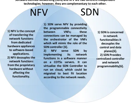
Software defined network (SDN) and NFV are two different independent technologies; however, they are complementary to each other. SDN technology started as a project targeting the network functionalities at Stanford University in 2007. SDN decouples the control plane from the data plane in the network. The control plane is responsible for network management such as path computation. It is centralized and implemented in the SDN controller, which provides the necessary computational power to achieve the goal [6]. Data plane is responsible for transporting the traffic. It is implemented in open flow switches. They are programmable switches that provide application programming interface (API) to be managed and controlled by the SDN controller. SDN will serve NFV by providing the programmable connectivity between VNFs; these programmable connections can be managed by the orchestrator of the VNFs that mimic the role of the SDN controller [6]. On the other hand, NFV can serve SDN by implementing its network functions as software application on COSTs servers. It can virtualize the SDN controller
to run on cloud, which could be migrated to the best-fit location based on to the network needs. Fig.2.3. lists how NFV and SDN differ and complement each other.
NFV
SDN
Software‐Defined Networking (SDN) and NFV are two different independent
technologies; however, they are complementary to each other.
1) SDN serve NFV by providing
the programmable connectivity
between VNFs; these
connections can be managed by
the orchestrator of the VNFs
which will mimic the role of the
SDN controller [6].
2) NFV serve SDN by
implementing its network
functions in a software manner
on a COTSs servers. It can
virtualize the SDN Controller to
run on cloud, which could be
migrated to best fit location
according to the network needs.
1) SDN is concerned
in network
functionalities it
decouples the
control and data
planes[6]. 2) SDN Provides
centralized controller
and network
programmability[6]. 1) NFV is the concept
of transferring the
network functions
from dedicated
hardware appliances
to software‐based
applications. 2) NFV decouples the
network functions
from the proprietary
hardware without
affecting the
functionality.
Fig. 2.3 NFV differs from SDN.
2.4
NFV Framework
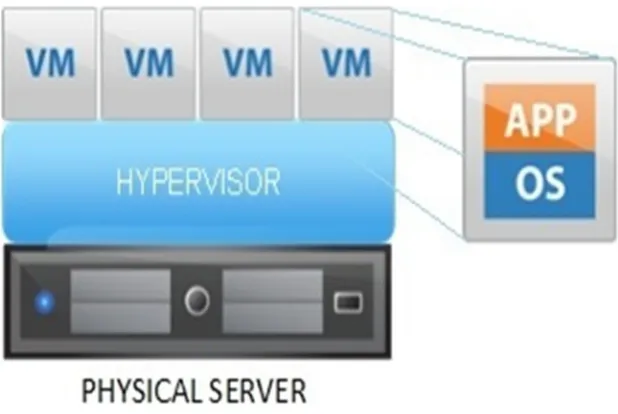
The basic components of virtualized platforms where NFV is deployed, are listed below:
1) Physical server: The physical server is the bare-metal machine that has all the physical resources such as CPU, storage, and random access memory (RAM). 2) Hypervisor: The hypervisor, or virtual machine monitor, is the software that runs
3) The guest virtual machine: A piece of software that emulates the architecture and functionalities of a physical platform on which the desired application is executed.
Virtual machines (VMs) are deployed on high-volume servers that can be located in datacenters, at network nodes, or in end-user facilities. Moreover, most VMs provide on-demand computing resources using cloud enviroments. Cloud-computing services may be offered in various formats [4]; as shown in Fig. 2.5:
1) Infrastructure as a service (IaaS) is referred to as hardware as a service (HaaS). The service provider offers the computing resources (CPU, storage and RAM) to the user without any specific operating system or application preinstalled on the resources by the service.
2) Platform as a service (PaaS) is a computing environment that enables the development and implementation of applications without the hassle of managing the underlying software and hardware.
3) Software as a service (SaaS), referred to as software on demand is a service of providing a specific application (like office, management, or CAD software) to the end-user over the web.
4) Network as a service (NaaS): There is no standard definition NaaS. NaaS is often considered to be provided under IaaS or as a standalone service that provides the connectivity between network nodes, datacenters, virtual machines, and end-user premises.
Fig. 2.5 The cloud services.
The NFV technology takes advantage of the infrastructure and networking services (IaaS and NaaS) to form the network function virtualization infrastructure (NFVI) [5].
Fig. 2.6 NFV framework [5].
2.5
Proposed Placement of Framework Entities
recovery, more efficiently to meet the specified quality-of-service requirements of VMs (VNFs and APPs) [5].
The virtualization layer consists of a cross-platform virtual resource manager that runs on top of the hypervisor to ensure the portability and flexibility of VNF independently of the hypervisor. OpenStack, Eucalyptus, oVirt, OpenNebula, and Nimbula are examples of cross-platform virtual layers [7]. The virtual machine hosts VNF and its element-management system (EMS). Each VNF instance has its private EMS to reduce complexity when migrating an existing VNF or initiating a new one. Operations and business support systems with VNF infrastructure description entities are deployed in a centralized form which provides uniformity of VNF software images and minimize database fragmentation. The proposed placements are illustrated in Fig.2.7.
2.6
NFV Ecosystem
Service providers have shown keen interest in NFV. Observing this interest, telecom equipment vendors and IT companies have started to investigate different aspects of NFV realization. Leading telecommunication equipment vendors like Ericsson, Nokia, Alcatel-Lucent, and Huawei have already started to adopt and upgrade their equipment to support NFV [8]. Moreover, leading IT companies that provide carrier grade software like Wind River, 6wind, Qosmos, and HP have been working closely with Intel to optimize their software on Intel processors in order to achieve higher packet processing computations that enable NFV and SDN on COTS platforms [9]. Intel has released the Data Plane Development Kit (DPDK) and has scheduled the release of signal processing development kit in its software development roadmap to extend and speed up NFV and SDN adoption [10]. Service providers started experimenting with these NFV products and put the devices under heavy testing to ensure that they will meet the expectations as carrier-grade products [11].
2.7
NFV Challenges and Requirements
Although NFV is a promising solution for telecommunications service providers, it faces certain challenges that could degrade its performance and hinder its implementation in the telecommunications industry. In this section, some of the NFV requirements and challenges, and proposed solutions are discussed. Table 2.1 summarizes this section.
2.7.1
Security
Security is an important aspect of the telecommunications industry. NFV should obtain a security level close to that of a proprietary hosting environment for network functions. The best way to achieve this security level is by dividing it according to functional domains. Security in general can be defined according to the following functional domains:
1) Virtualization environment domain (hypervisor) 2) Computing domain
4) Application domain.
Security attacks are expected to increase when implementing network functions in a virtualization environment. A protected hypervisor should be used to prevent any unauthorized access or data leakage. Moreover, other processes such as data communication and VM migration should run in a secure environment [12]. NFV uses APIs to provide programmable orchestration and interaction with its infrastructure. These APIs introduce a higher security threat on VNFs [13].
2.7.2
Computing Performance
The virtual environment underlying hardware server characteristics such as processor architecture, clock rate, cache memory size, memory bandwidth, and speed has a profound impact on VNF performance. VNF software design also plays a major role in VNF performance. VNF software can achieve high performance using the following techniques:
1) A high-demand VNF should be implemented using multi-threading techniques and in a distributed and scalable fashion, in order to execute it on multiple cores or different hosts.
2) Software instances should have independent memory structures to avoid operating-system deadlocks.
3) VNF should implement its own network stack and avoid networking stacks implementation in the operating system, which consume large amounts of computing resources.
4) Direct access to input/output interfaces should be used whenever possible to reduce latency and increase data throughput.
5) Processor affinity techniques should be used to take advantage of cache memories.
2.7.3
Interconnection of VNFs
Unlike the classical approach of interconnecting network functions by a direct connection or through Layer 2 (L2) switches, a virtualized environment uses different approaches. In a virtualized environment, virtual machines can be connected in different scenarios [14]:
1) If two VNFs are on the same physical server and on the same local-access network (LAN), they are connected through the same Vswitch.
2) If two VNFs are on the same physical server but on different LANs, the connection passes through the first Vswitch to the network interface controller (NIC), then to the external switch, and back again to the same NIC. This NIC forwards the connection to the Vswitch of the second LAN and then to the VNF.
3) If two VNFs are on different servers, the connection passes through the first Vswitch to the NIC and then to an external switch. This switch forwards the connection to the NIC of the desired server. Finally, this NIC forwards it to its internal Vswitch and then to the destination VNF.
Some NICs provide direct access from the virtual machine. These NICs are single-root I/O virtualization (SR-IOV) compliant. They offer faster and higher throughput to virtual machines. Each connectivity technique has its own advantages in terms of performance, flexibility, and isolation. Virtual interfaces managed by the
hypervisor have lower performance compared to virtual interfaces offered by SR-IOV-compliant NICs. However, virtual interfaces provided by the hypervisor are simpler to configure, and support VM live migration in a simpler way. The correct choice depends on the VNF workloads. Fig.2.8. illustrates the VNF interconnection cases.
2.7.4
Portability
Virtualized network functions can be deployed in different ways. Each way has its own advantages and drawbacks. Virtualized network functions that are executed directly on bare-metal ensure predictable performance because mappings of software instances to hardware are predictable. This kind of deployment sacrifices resource isolation and makes software-instance security difficult to achieve because multiple software appliances are executed as processes on the same operating system. In addition, the designed software would be OS-dependent.
Deploying virtual network functions through a virtual environment improves portability and ensures that hardware resources are viewed uniformly by the VNF. This deployment also enables each VNF to be executed on its specific operating system while remaining unaware of the underlying operating system. In addition, VNF resource isolation is ensured because VNFs are executed on independent VMs managed by the hypervisor layer, which guarantees no unexpected interactions between them. Strict mapping of resources should be used to guarantee resource isolation.
2.7.5
Operation and Management
Virtual network functions should be implemented as simple drag-and-drop operations in the orchestration management system. To make this a reality, both VNFs and computing infrastructure should be described using standard templates that enable automated management.
interactions are used to interact with the NFVI and request information from other framework entities. In addition, they are used to request information about policies, VNF software images, VNF descriptions, or network forwarding graphs.
2.7.6
Co-existence with Legacy Networks
Virtual network functions should be able to coexist with legacy network equipment. It means that a) it should be able to interact with legacy management systems with minimal effects on existing networks, b) the network forwarding graph should not be affected by the existence of one or more VNFs, and c) a secured transition should be ensured between VNF instances and physical functions, without any service interruption or performance impacts [15].
2.7.7
Carrier-Grade Service Assurance
Challenge Description Solutions and Requirements
Security
Virtualization security risks according to functional domains:
1) Virtualization environment domain (Hypervisor):
Unauthorized access or data leakage. 2) Computing domain:
Shared computing resources: CPU, memory…etc.
3) Infrastructure domain (networking):
Shared logical-networking layer (Vswitches).
Shared physical NICs.
Security implementations according to functional domains:
1) Virtualization environment domain (Hypervisor):
Isolation of the served virtual-machine space, with access provided only with authentication controls.
2) Computing domain:
Secured threads.
Private and shared memory allocations should be erased before their re-allocation.
Data should be used and stored in an encrypted manner by which exclusive access is provided only to the VNF. 3) Infrastructure domain (networking):
Usage of secured networking techniques (TLS, IPSec, or SSH).
Computing performance
The virtualized network function should provide comparable performance to network functions running on proprietary hardware equipment.
VNF software could achieve high performance using the following techniques:
Multithreading to be executed over multiple cores, or could be scaled over different hosts.
Independent memory structures to avoid operating-system deadlocks.
VNF should implement its own network stack.
Direct access to input/output interfaces.
Processor affinity techniques should be implemented.
VNF interconnection
Virtualized environment has different approaches from classical network function interconnection.
VNFs should take advantage of accelerated Vswitches and use NICs that are single-root I/O virtualization (SR-IOV) compliant.
Portability
VNFs should be decoupled from any underlying hardware and software. VNFs should be deployable on different virtual environments to take advantage of virtualization techniques like live migrations.
The VNF development should be based on a cross-platform virtual resource manager that ensure its portability.
Operation and management Existence with legacy networks Carrier-grade service assurance
VNFs should be easy to manage and migrate with existing legacy systems without losing the specification of a carrier-grade service.
To achieve the desired operation and management performance, a standard template of NFV framework entities should be well-defined. It should be able to interact with legacy management systems with minimal effects on existing networks. The NFV orchestrator must monitor network function performance almost in real time.
2.8
Use Cases and Services
The Network Function Virtualization technology in principle considers all network functions for virtualization through well-defined standards. Most likely, NFV services will be provided in a similar way to IT virtualization service models. NFV service models include NFVI as a Service (NFVIaaS), VNF as a Service (VNFaaS), and Virtual Network Platform as a Service (VNPaaS). Service providers will choose between these service models to serve their network-connectivity needs and use cases. Some of the use cases will include, for example, fixed-access network function virtualization, content-delivery network virtualization, and home environment virtualization [17].
2.8.1
NFVI as a Service (NFVIaas)
The NFV Infrastructure can be considered as providing the required infrastructure for an environment in which virtualized network functions can be executed. The NFVIaaS should provide computing and networking capabilities comparable to IaaS and NaaS in cloud computing services. Compatible is assured with any IT application since it provides a standard IT computing resources.
2.8.2
VNF as a Service (VNFaaS)
In VNFaaS the VNF is an application provided by the service provider to the service consumer. The consumer will not be in charge of managing, controlling the NFVI, and VNF instances. Consumers of the VNFaaS do not have to develop or own the VNF application rather they can obtain them on an expense basis from the Service Provider as needed. The Service Provider allocates resources of NFVI and manages the VNF in order to deliver the desired network functionality with the required QoS.
2.8.3
Virtual Network Platform as a Service (VNPaaS)
2.8.4
Fixed Access Network Functions Virtualization
The Virtualization in the fixed access network will mainly target the network functions in the fiber-to-distribution nodes. They are deployed in street cabinets, customer premises, or underground. The hardware footprint of these network functions should be in compact form. Furthermore, the hardware should run with a very low power consumption and assure durability with minimum failure. Implementing the fix access network function with NFV technology will expunge the challenges. NFV offers lower hardware complexity, footprint, and energy consumption. Moreover, NFV will permit rapid service upgrades and deployment to meet all technology revolutions that fix access network is sighting.
VNFs are implemented mainly in Layer 2 (L2) and Layer 3 (L3) network functions in the fixed access network. As for layer 1 functions will be considered for virtualization later. Layer 1 has the signal processing computations that need to be delivered in real-time manner to avoid latency issues. VNFs most probably will be seen at first in L2 and L3 network functions of Multiple Dwelling Units, digital subscriber line access multiplexer, and cable modem termination system.
2.8.5
Content Delivery Networks Virtualization
automated management and orchestration. Efficient resource utilization and lower footprint is achieved through NFV automated resource allocations. In addition, Service resilience is achieved through NFV automated VNF deployment.
2.8.6
Home Environment Virtualization
As the home environment services like internet, VoIP, and on-demand video streaming are increasing ,more client equipment are needed to be installed at the customer home. Service providers have to install a residential gateway to provide all these services to the customer. Furthermore, when a new service is going to be released the customers have to upgrade their home equipment to have access to these services. Virtualizing the home environment network functions such as the residential gateway and digital box will provide a great deal for the service providers and customers. Virtualizing the home environment function and implementing these functions on the cloud introduces a network bandwidth challenge. Higher bandwidth connection should be provided between the customer home and the service provider network. With video streaming in high-definition, VoIP, and internet access the network bandwidth should be almost 1 Gigabit per second with low latency to assure the service quality. This requirement would be achieved in the near future since some service providers have started offering these kind of high-speed connections.
2.8.7
Mobile Network Virtualization
layer. Therefore, virtualization first is considered for implementation in the higher network stack layers. Considering eNodeB, which is the fourth-generation network (LTE) base station, virtualization will be implemented in layer 3 and then in layer 2 [17]. Layer 3 hosts the functionalities of the control and data plane that connects to the mobile core network. Layer 2 hosts the packet data convergence protocol (PDCP), radio link control (RLC), and media access control (MAC) network functions. Virtualizing layer 2 and 3 of the base station provide the opportunity to offer a centralized computing infrastructure for multiple base stations, which lead to lower-cost base stations because only baseband signal processing should be implemented on-site. Furthermore, service providers will benefit from sharing their remote base-station infrastructure to achieve better area coverage with minimum CAPEX and OPEX investment. There are also some efforts to centralize the L1 functionalities of several base stations [18]. They will be able to upgrade VNFs to support multiple telecommunications technologies and adapt them for new releases.
Fig. 2.9 Base station virtualization evolution.
2.9
Virtualization of the Evolved Packet Core (EPC)
introduced in release 8 as a simplified all-IP core network architecture. It is designed to permit mobile broadband services by combining leading-edge IP infrastructure and mobility. Moreover, EPC is designed to support a variety of access technologies [19]. The rapid increase in connectivity demand has led service providers to undertake more CAPEX and OPEX investments beyond financial sense in their mobile core network infrastructure. From this point onward, it is becoming essential to have a flexible, robust, and easily manageable network; a network that could be scaled on-demand in real time and would be easily manageable. Virtualizing EPC offers all these benefits to service providers.
The basic EPC entities to support IP connectivity in LTE are the following:
1) The mobility management entity (MME) is the main control-plane entity in the LTE network.
2) The serving gateway (SGW) is responsible for routing and forwarding user data packets from and to the base station.
3) The packet data network gateway (PDN-GW) (PGW) ensures connectivity between the user data plane and external networks.
4) The Home Subscriber Server (HSS) is the central user information database. 5) The policy and charging rules function (PCRF) is responsible for passing and
deciding the policies and charging in real time for each service and user.
2.10
Grouping EPC Entities in the NFV Environment
Implementing a virtualized EPC (vEPC) is the prime objective of the telecommunication equipment vendors. Since EPC encompasses multiple functionalities, instantiation of VNF in cloud has a tremendous effect on the performance and hence, VNFs are grouped together based on their interactions and workload. Generally, it is beneficial to instantiate each group in one physical server, or one local network depending on the workload.
proposed approach maintains the two EPC principles of flat architecture and decoupling of the control and data planes. The grouping approach divides the entities into four segments. These are listed below and summarized in Table 2.2 and illustrated in Fig.2.10.
Since understanding the LTE framework is necessary to truly grasp the benefit of the proposed grouping. Please refer to [19] for a comprehensive study of the LTE architecture.
2.10.1 Segment One
Furthermore, TLS and SSL are application-layer security protocols that provide better flexibility on a virtualized platform [22].
Fig. 2.10 vEPC Entities Grouping.
2.10.2 Segment Two
authentication and charging functions. The SGSN is assumed in the proposed approach as almost all service providers support 2G and 3G networks besides their 4G networks. The SGSN is not combined with any EPC entities because the SGSN has a control and data plane, which contradicts the EPC architectural decoupling principle. The HLR is the database that conserves the user information in a Global System for Mobile (GSM) core network. The HLR FE is combined with the SGSN for almost the same reasons that combine the MME with the HSS FE. Moreover, this combination enables a unified database and supports the combination of the existing SGSN with the Gn interface to the EPC system. Gn is an interface that is based on the GPRS tunneling protocol (GTP).
2.10.3 Segment Three
In the proposed grouping, the PGW is migrated with the SGW. This merging of the two plane entities follows the flat architecture principle to minimize the number of data-plane processing nodes. Implementing the two entities in one VM or VNF will benefit from centralized processing in the data plane and helps to overcom the processing and network bottlenecks. In this segment, user data are not routed or transferred to the PGW after being served by the SGW. Instead, the segment has direct access to the PGW, which routes it to external networks. Centralized processing in the virtualized environment enables applications to apply the CPU affinity procedure, leading to an efficient use of CPU cache memory. In addition, this merge avoids unnecessary routing through Vswitches, which are a major bottleneck in virtual environments. Higher VNF data throughput could also be achieved using direct network interface access, in order to meet the required latencies and quality of service of the PGW and the SGW. This migration leads to a better data monitoring and charging in addition to the elimination of signaling-transaction traffic between the SGW and the PGW. All signaling signaling-transactions are carried out internally.
2.10.4 Segment Four
because the PCRF requests user information to generate the required policies for each established bearer. This approach prevents information exchange from overwhelming the network node, minimizes the latency of policy-function generation, and speeds policy enforcement to the PGW. As for the OCS and OFCS, the OCS is used to charge network users in a real-time manner, as in a pre-paid credit system, whereas the OFCS is used to charge users after the session is ended, as in billing services known as “pay as you go”. The OCS and the OFCS interact with the PCRF and the PCEF to gather information about the session and enforce charging policies to the PGW, such as terminating the communication session when the credit limit has been exceeded. In addition, this segment groups all the entities that need to interact with the OSS/BSS. Limiting fragmentation of OSS/BSS interactions leads to more efficient control over network services.
![Fig. 1.4 2N redundancy model [6].](https://thumb-us.123doks.com/thumbv2/123dok_us/7749859.1270327/23.612.207.443.387.630/fig-n-redundancy-model.webp)
![Fig. 1.5 N+1 Redundancy Model [6].](https://thumb-us.123doks.com/thumbv2/123dok_us/7749859.1270327/24.612.109.536.286.643/fig-n-redundancy-model.webp)
![Fig. 1.6 N-way redundancy model [6].](https://thumb-us.123doks.com/thumbv2/123dok_us/7749859.1270327/25.612.114.535.228.566/fig-n-way-redundancy-model.webp)
![Fig. 1.7 N-way active redundancy model [6].](https://thumb-us.123doks.com/thumbv2/123dok_us/7749859.1270327/26.612.113.534.154.545/fig-n-way-active-redundancy-model.webp)
![Fig. 2.2 Service provider revenues vs traffic [2].](https://thumb-us.123doks.com/thumbv2/123dok_us/7749859.1270327/39.612.121.524.82.355/fig-service-provider-revenues-vs-traffic.webp)