Available online:
https://edupediapublications.org/journals/index.php/IJR/
P a g e | 20211 M u s kaawaar Kiran , 2 K Siv a Ku mara Swamy
1M.Tech student, Dept. of ECE, Sphoorthy Engineering College,Hyderabad,Telangana, India 2 Professor Dept. of ECE, Sphoorthy Engineering College,Hyderabad,Telangana, India
A BSTRA CT: The high performance Arithmetic units are essential since the speed of the digital processor depends heavily on the speed of the Arithmetic units used is the system.Using quaternary signed digit (QSD) number system both carry free addition and borrow free subtraction can be achieved. The QSD number system requires a special set of prime modulo based logic for arithmetic operations. Using a high radix number system such as Quaternary Signed Digit(QSD),a carry free arithmetic operation can be achieved. Arithmetic Operations such as addition and subtraction for large numbers like 64 and 128 can be computed without the propagation of carry using QSD number system. Design is simulated and analyzed using Xilinx 14.4 ISE Simulator.
KEYW ORDS- Carry free addition, QSD, Redundancy,VLSI
I. INTRODUCTION
Arithmetic operations are widely used and play important roles in various digital systems such as computers and signal processors. QSD number representation has attracted the interest of many researchers. Additionally, recent advances in technologies for integrated circuits make large scale arithmetic circuits suitable for VLSI implementation [1]. However, arithmetic operations still suffer from known problems including limited number of bits, propagation time delay, and circuit complexity. These high performance arithmetic’s are essential since the speed of the digital processor depends heavily on the speed of the adders used is the system. Also, it serves as a building block for synthesis of all other arithmetic operations. Adders are most commonly used in various electronic applications e.g. Digital signal processing in which adders are used to perform various algorithms like FIR, IIR etc. In past, the major challenge for VLSI designer is to
reduce area of chip by using efficient Optimization techniques. Then the next phase is to increase the speed of operation to achieve fast calculations like, in today’s microprocessors millions of instructions are performed per second. Speed of operation is one of the major constraints in designing DSP processors. The redundancy associated with signed-digit numbers offers the possibility of carry free addition. The redundancy provided in signed-digit representation allows for fast addition and subtraction because the sum or difference digit is a function of only the digits in two adjacent digit positions of the operands for a radix greater than 2, and 3 adjacent digit positions for a radix of 2. Thus, the add time for two redundant signed-digit numbers is a constant independent of the word length of the operands, which is the key to high speed computation. The quaternary logic uses 0, 1, 2 and 3 logic levels. The advantage of carry free addition offered by QSD numbers is exploited in designing a fast adder circuit. Additionally, adder designed with QSD number system has a regular layout which is suitable for VLSI implementation which is the great advantage over the RBSD adder. An Algorithm for design of QSD adder is proposed.
Binary signed-digit numbers are known to allow limited carry propagation with a somewhat more complex addition process requiring very large circuit for implementation [3]. A special higher radix-based (QSD) representation of binary signed-digit numbers not only allows carry-free addition and borrow-free subtraction but also offers other important advantages such as simplicity in logic and higher storage density. QSD numbers are represented using 3-bit 2’s complement notation. Each number can be represented by
Available online:
https://edupediapublications.org/journals/index.php/IJR/
P a g e | 2022𝐷 = ∑ 𝑋𝑖4
𝑛−1
𝑖 =0
Where xi can be any value from the set {3, 2, 1, 0, 1, 2, 3} for producing an appropriate decimal representation. A QSD negative number is the QSD complement of the QSD positive number i.e., 3 = 3, = −2 and 1 = −1. For example, 1233QSD = 2310 and
1233QSD = −2310.
The computation speed and circuit complexity increases as the number of computation steps decreases. Two-step schemes appear to be a prudent choice in terms of computation speed and storage complexity. Quaternary is the base 4 redundant number system. The degree of redundancy usually increases with the increase of the radix. The signed digit number system allows us to implement parallel arithmetic by using redundancy.
The major challenges in VLSI design are reducing the area of chip and increasing speed of the circuit. Reducing area can be achieved by optimization techniques and number of instructions executed per second increases as speed increases. The performance of a digital system depends upon performance of adders. The objective is to design carry free adder using QSD number system to achieve fast addition with the help of VHDL, which integrates novel design of high speed QSD adder.
II. SYSTEM DESIGN OF QSD ADDER
Addition is the most important arithmetic operation in digital computation. A carry-free addition is highly desirable as the number of digits becomes large. We can achieve carryfree addition by exploiting the redundancy of QSD numbers and the QSD addition. The redundancy allows multiple representations of any integer quantity i.e., 610 =
12QSD = 22QSD. In QSD number system carry
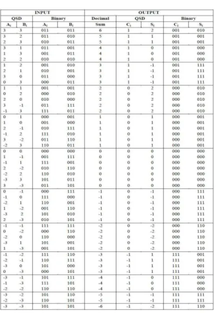
propagation chain is eliminated, which reduce the computation time substantially, thus enhancing the speed of the machine. As range of QSD number is from -3 to 3, the addition result of two QSD numbers varies from -6 to +6. Table I depicts the output for all possible combinations of two
numbers. The decimal numbers in the range of -3 to +3 are represented by one digit QSD number. As the decimal number exceeds from this range, more than one digit of QSD number is required. For the addition result, which is in the range of -6 to +6, two QSD digits are needed. In the two digits QSD result the LSB digit represents the sum bit and the MSB digit represents the carry bit. To prevent this carry bit to propagate from lower digit position to higher digit position QSD number representation is used. QSD numbers allow redundancy in the number representations. The same decimal number can be represented in more than one QSD representations. So we choose such QSD represented number which prevents further rippling of carry. To perform carry free addition, the addition of two QSD numbers can be done in two steps [4]:
Step 1: First step generates an intermediate carry and intermediate sum from the input QSD digits i.e., addend and augend.
Step 2: Second step combines intermediate sum of current digit with the intermediate carry of the lower significant digit.
So the addition of two QSD numbers is done in two stages.
First stage of adder generates intermediate carry and intermediate sum from the input digits.
Second stage of adder adds the intermediate sum of current digit with the intermediate carry of lower significant digit.
To remove the further rippling of carry there are two rules to perform QSD addition in two steps:
Ru le 1: First rule states that the magnitude of the intermediate sum must be less than or equal to 2 i.e., it should be in the range of -2 to +2.
Ru le 2: Second rule states that the magnitude of the intermediate carry must be less than or equal to 1 i.e., it should be in the range of -1 to +1.
Available online:
https://edupediapublications.org/journals/index.php/IJR/
P a g e | 2023adder can have the range of -6 to +6. When the second step QSD adder adds the intermediate sum of current digit, which is in the range of -2 to +2, with the intermediate carry of lower significant digit, which is in the range of -1 to +1, the addition result cannot be greater than 3 i.e., it will be in the range of -3 to +3. The addition result in this range can be represented by a single digit QSD number; hence no further carry is required. In the step 1 QSD adder, the range of output is from -6 to +6 which can be represented in the intermediate carry and sum in QSD format as shown in table I.
We can see in the first column of Table I that some numbers have multiple representations, but only those that meet the above defined two rules are chosen.
Examp le: To perform QSD addition of two numbers A = 107 and B = -108 (One number is +ve and one number is –ve).
First convert the decimal number to their equivalent QSD representation:
(127)10 = 1 × 43 + 3 × 42 + 3 × 41 + 3× 40 = (1 3 3
3)QSD
(128)10 = 1 × 43 + 2 × 42 + 3 × 41 + 0× 40 = (2 0 0
0) QSD
Hence, (-128)10 = (2 0 0 0) QSD
Table I: The Intermediate Carry and Sum between -6 To +-6
The chosen intermediate carry and Intermediate sum are listed in the last column of Table I as the QSD coded number. This addition process can be well understood by following examples:
The main advantage of Quaternary logic is that it reduces the number of required computation steps for developing digital design. Furthermore memory, control unit, and processor can be carried out faster if the Quaternary logic is easily employed and memory utilization also less than binary. These advantages have been shown to be useful for the design of Quaternary computers, for digital filtering. Quaternary representation of admits sign convention also.
transforms for encoding and more efficient for Compression, error correction, and state assignment, representation of discrete information and in automatic telephony.
utilization of transmission channels because of the higher information content carried by every line. It gives exact and more efficient error detection and correction codes and possesses potentially higher density of information storage. We can achieve a carry free arithmetic operation by using higher radix number system such as QSD (Quaternary Signed Digit). Signed digit number system has redundancy associated with it. The redundancy provided in signed digit number system offers the possibility of carry free arithmetic operations which in terms allows for faster processing. In signed digit representation of the system the add time for two redundant signed digit numbers is a constant independent of the word length of the operands which is the key to high speed computation. Binary signed digit numbers allows limited carry propagation with a more complex addition process which requires very large circuit for implementation [1][4].
Available online:
https://edupediapublications.org/journals/index.php/IJR/
P a g e | 2024reduce the circuit area and circuit cost and power efficiency at the same time.
III. THE PROPOSED A PPROA CH
The QSD carry free addition involved the two steps .the first step helps to generates intermediate carry and intermediate sum from the added and augend. second step involves the to combines the intermediate sum of the current digit with the carry of the lower significant digit. To prevent from further rippling of the carry, two rules are also defined the according to first rule it states that the magnitude of intermediate sum must be equal to 2.the second rule defined as the magnitude of carry must be equal to 1.therefore, the magnitude of the second step output cannot be larger than the 3 which is represented by single-digit QSD number: due to this no further carry is required. The range of input number must in between -3 to +3,so the addition result must be in the range of -6 to +6 which needs two QSD digits. The lower significant digit is treated as sum and most significant bit is acts as carry. It contain one disadvantage also that is the generation of the carry can be avoided by mapping the two digit a pair of intermediate sum and intermediate carry such that the nth intermediate sum and the (n-1)th intermediatecarry
is never be form any carry generating pair (3,3),(3,2),(3,1),(3,3),(3,2),(3,1).
The finally we are getting the carry free addition, and here both inputs and output can be encoded in 3-bit 2’s complement binary number. The intermediate carry and sum are shown in binary formate shown in Table II.
At the input side, the addend Ai is represented by 3 variable input as A2, A1, A0 and the augend Bi is represented by 3 variable input as B2, B1, B0. At the output side, the intermediate carry IC is represented by IC2, IC1, IC0 and the intermediate sum IS is represented by IS2, IS1, IS0. The six variable expressions for intermediate carry and intermediate sum in terms of inputs (A2, A1, A0, B2, B1 and B0) can be derived from Table II. So we get the six output expressions for IC2, IC1, IC0, IS2, IS1 and IS0. As the intermediate carry can be represented by only 2 bits, the third appended bit
IC2 is equal to IC1 so the expression for both outputs will be the same[5].
The VHDL code for intermediate carry and sum generator in step 1 adder, by taking the six inputs (A2, A1, A0, B2, B1 and B0) and six outputs (IC2, IC1, IC0, IS2, IS1 and IS0), has been written. The VHDL code is compiled and simulated using Xilinx software. The design is synthesized on FPGA device xc9536xvPC44 in Xilinx XC9500XV technology. Using 6 variable K-map, the logic equations specifying a minimal hardware realization for generating the intermediate carry and intermediate sum are derived. The minterms for the intermediate carry (IC2 , IC1, IC0) are:
Available online:
https://edupediapublications.org/journals/index.php/IJR/
P a g e | 2025Table II: The conversion between the inputs and outputs of the intermediate carry and intermediate
sum
IV RESULT A ND DISCUSSION
In this paper, we propose a high speed and low power QSD addition unit. Xillinx tool gives us an easy way to analyze our results to get the best out of them. The simulation results of the Adder units in QSD are shown below Fig.2.
Fig.2:Simu lation Result of QSD Addition
IV. CONCLUSION
he proposed QSD adder is is written in VHDL code and the design is simulated and synthesized using software Xilinx 14.4 ISE simulator. The QSD addition and subtraction are entrenched and proved. The QSD ALU design performance is better comparing to other designs. The QSD adder complexity is linearly proportional to the number of bits which are of the same order as the simplest BCD and other adder, such as the ripple carry adder. These QSD adders can be used as a building block for other arithmetic operations such as multiplication, division, etc.
REFERENCES
[1] Sachin Dubey, Reena rani “VLSI Implementation of Fast Addition using Quaternary Signed Digit Number System” IEEE International Conference on Emerging Trends in Comp…ICECCN 2013.
[2] Neha W.Umredkar, M.A.Gaikwad, Ph.D. “Review of Quaternary Adders in Voltage Mode MultiValued Logic” International Journal of Computer Applications (0975 – 8887) “Recent Trends in Engineering Technology -2013”.
[3] Reena Rani, Neelam Sharma, L.K.Singh, “FPGA Implementation of Fast Adders using Quaternary Signed Digit Number System” IEEE proceedings of International Conference on Emerging Trends in Electronic and Photonic Devices & Systems (ELECTRO-2009), pp 132-135, 2009.
Available online:
https://edupediapublications.org/journals/index.php/IJR/
P a g e | 2026proceedings of International Conference on Control,
Automation, Communication and Energy Conservation - 2009, 4th-6th June 2009.
[5] P.K. Dakhole, D.G. Wakde, “Multi Digit Quaternary adder on Programmable Device: Design and verification”, International Conference on Electronic Design, pp. 1-4, Dec 2008.
[6] F. Kharbash and G. M. Chaudhry, “Reliable Binary Signed Digit Number Adder Design”, IEEE Computer Society Annual Symposium on VLSI, pp 479-484, 2007.
[7] John Moskal, Erdal Oruklu and Jafar Saniie, “Design and Synthesis of a CarryFree Signed-Digit Decimal Adder”, IEEE International symposium on Circuits and Systems, pp 1089-1092, 2007.
[8] Reilly, E.D. (2003). Milestones in computer science and information technology. Greenwood Press. p. 183. ISBN 1-57356-521-0.
[9] A.A.S Awwal, Syed M. Munir, A.T.M. Shafiqul Khalid, Howard E. Michel and O. N. Garcia, “Multivalued Optical Parallel Computation Using An Optical Programmable Logic Array”, Informatics, vol. 24, No. 4, pp. 467-473, 2000.
[10] O. Ishizuka, A. Ohta, K. Tannno, Z. Tang, D. Handoko, “VLSI design of a quaternary multiplier with direct generation of partial products,” Proceedings of the 27th International Symposium on Multiple-Valued Logic, pp. 169-174, 1997.
[11] A.A.S. Awwal and J.U. Ahmed, “fast carry free adder design using QSD number system,” proceedings of the IEEE 1993 national aerospace and electronic conference, vol 2,pp 1085-1090,1993.
[12] Eurich, J.P. and Roth, G. (1990): "EDIF grows up". IEEE Spectrum, Vol. 27, Issue 11, pp. 68 - 72.
Bio Data
A u th o r
M u s kaawaar Kiran currently pursuing M.Tech in Electronics and Communication Engineering in Dept. of ECE, Sphoorthy Engineering College, Hyderabad, Telangana, India.
Co -A u th o r