Available online: https://edupediapublications.org/journals/index.php/IJR/ P a g e | 1766
Simulation And Implementation of Three-Phase Induction
Motor drive Quasi-Z-Source Fed Inverter with O & P MPPT
SUNDARI SRAVAN KUMAR
Ph.d SCHOLAR FROM SHRI JAGDISHPRASAD JHABARMAL TIBREWALA UNIVERSITY
Dr. Yerra Sreenivasa Rao
Professor from Department of EEE ,
Bvsr Engineering College, Ongole,A.P
ABSTRACT:
This paper proposes utilization of Quasi-Z-source inverter as a solitary stage control change idea for
movable speed drives in photovoltaic applications. Sun based board proficiency is low, To track the
most extreme power from board, Perturb and Observe (P&O) calculations utilized in Maximum Power
Point Tracking (MPPT). Yield Torque-Speed attributes of Induction Machine has been demonstrated and
looked at by MATLAB/Simulink programming.
Keywords: PV Array, P&O method, with MPPT state, without MPPT state, Induction Motor (IM)
1. INTRODUCTION
The most ideal approach to use the electric vitality created by the PV exhibit is to convey it to the AC mains
specifically, without utilizing battery stockpiling. The nonappearance of fuel cost, clamor, contamination the sun
powered vitality source is utilizing for sustainable power source among every single other source. The support cost less.
Be that as it may, the PV framework has low productivity due light and temperature. To enhance the proficiency of PV
framework, Maximum Power Point Tracking (MPPT) has been produced, for example, P&O, Constant Voltage et
cetera. Already dc source will be a supply and capacity to semi Z-source inverter with RL stack. In this paper sun
oriented board will be an info source to semi Z-source inverter with MPPT P&O Techniques with Induction engine
have been reproduced.
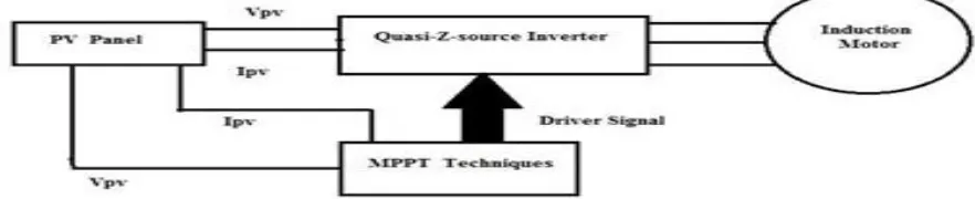
2. Square Diagram
The square chart of by and large PV change utilizing MPPT is appear in figure 1. The created voltage (VPV) and
current (IPV) from PV exhibit are contribution for MPPT control. This MPPT control square is figure the reference
voltage. By looking at the reference voltage and PV voltage, the exchanging beats (driver signals) produced to switch
International Journal of Research
Available at https://edupediapublications.org/journalse-ISSN: 2348-6848 p-ISSN: 2348-795X Volume 04 Issue 08
July 2017
Available online: https://edupediapublications.org/journals/index.php/IJR/ P a g e | 1767
Figure 1: Block diagram of overall PV conversion using MPPT
3. Modelling of PV Array
The equivalent circuit of a PV cell is as shown in Figure 2.Where Iph represents the cell photo current, I0 represents the diode saturation current, I and V are cell output current and cell output voltage respectively. Rp is shunt resistance. Rs are series resistance. They ideal PV module for one diode circuit.
Saturation Current (I0):
Saturation current of PV system varies with the cell temperature can be determined by given equation.
3.4. Output Current (I):
The equation for output current of the PV system of single diode model presented in Figure 1 is given by,
From the above equations,
Available online: https://edupediapublications.org/journals/index.php/IJR/ P a g e | 1768 In this paper Savitha P B make 178 Wp PV module is taken and the name-plate details are given in Table 1.
4. MPPT Algorithm
To enhance productivity of sun oriented board Maximum Power Point Tracking (MPPT) is utilized. It
incorporates electronic framework to work the PV modules in a way that enables the modules to create
all the power. To track the most extreme power a few strategies are utilized. The most mainstream
procedures are Perturb and Observe (P&O), Incremental Conductance(IC), Constant Voltage (CV),
Open Circuit Voltage, Neural systems and Fuzzy rationale. Every one of these strategies have their own
points of interest and disservices. The decision of the calculation relying upon the execution cost, time,
and many-sided quality, proficient to track most extreme power . In this paper Perturb and Observe
(P&O) method are utilized with steady and variable obligation cycle separately.
4.1. P&O Method
It is least difficult technique for MPPT to actualize. In this technique yield intensity of sun oriented is
International Journal of Research
Available at https://edupediapublications.org/journalse-ISSN: 2348-6848 p-ISSN: 2348-795X Volume 04 Issue 08
July 2017
Available online: https://edupediapublications.org/journals/index.php/IJR/ P a g e | 1769
obligation cycle D is expanded. For voltage diminishing with control expands obligation cycle D is
diminished.
The entire process shown as flowchart in Figure 5.5. Indution Motor
An electric engine is a gadget which changes over an electrical vitality into mechanical vitality.
This mechanical vitality at that point can be provided to different kinds of load. As air
conditioning supply is usually accessible. The air conditioner engines are named single and three
stage enlistment engines, synchronous engines and some exceptional reason engines. The
essential points of interest of three stage enlistment engines over different kinds are
self-beginning property, no need of self-beginning gadget, higher power factor, great speed control and
vigorous development. There are two sorts of rotor developments which are utilized for
acceptance engines are,
Squirrel confine rotor and
Slip ring or Wound rotor.
Here we utilized in Squirrel confine enlistment engine and its execution can be examined
through in MATLAB/Simulink.
6. Reproduction Results
International Journal of Research
Available at https://edupediapublications.org/journalse-ISSN: 2348-6848 p-ISSN: 2348-795X Volume 04 Issue 08
July 2017
Available online: https://edupediapublications.org/journals/index.php/IJR/ P a g e | 1771 In this paper, analysed the performance of Quasi-Z-source inverters in with and without P&O MPPT techniques in Induction Motor and the simulation designs are simulated using MATLAB/Simulink.
8.References
1. ” Modeling of 250WP Photovoltaic Module and its Performance analysis using MATLAB/Simulink”., Savith.P.B., Proceedings of IRF Journal Conference, 23’rd March 2014.
2. “An energy stored Quasi-Z-source inverter using SVPWM Techniques”., Dhanya.k.Thomas., International Journal of Electrical Research., Vol.2,Issue.7,July 2014.
3. ”Modelling oh solar power based Quasi-Z-source inverter to supply BLDC Motor”., Neethu Johnson., International Journal of Electrical Research and Innovative., Vol.2, Issue.2, Feb-2014.
4. “Comparative study of P&O and Incremental Conduction MPPT Algorithms”., I.William Christopher., AJER., Vol.2,Issue.12,2013.
5. “Three stage cascaded Quasi-Z-source inverter system for Renewable applications”,. Nisha.K.C.R, International Journal of Electrical Research, Vol.3, Issue.5, July 2013.
6. “A Comparison of Two MPPT Techniques for PV System in MATLAB/Simulink”., Sangita s. Kondawar., IJERD., Vol.2, Issue.7, Aug 2013.
7. ”Digital simulation of current-fed Quasi-Z-source inverter”, Kishor.G., International Journal of Electrical Research., Vol.3, Issue.4, aug 2013.
8. “Power Conditioning System for a grid connected PV Power generation using a Quasi-Z-source inverter”, Jong-Hysung Park., Journal of Power Electronics., Vol.10, No.1, Jan 2010.
9. “Analysis of sinusoidal Pulse with modulation control strategies for Quasi-Z-source inverter., Jani Das., International Journal of Electrical Research., Vol.2,Issue.9,Sep 2013.
10. “Photo voltaic Power injected to the grid with Quasi-Z-source inverter”, Gobi.M,. International Journal of Electrical Research, Vol.2, Issue.3, May 2014.