Analytical Study on Horizontal and Vertical
Irregularity in Structure under Seismic Load with
Shear Wall and Bracing
Swati More1, Dr. Vikram Patil2, Somanagouda Takkalaki3
1 Civil Engineering, B.R.Harne College of Engineering & Technology,
Mumbai, Maharashtra 421503, India
2
Civil Engineering, B.R.Harne College of Engineering & Technology, Mumbai, Maharashtra 421503, India
3 Civil Engineering, B.R.Harne College of Engineering & Technology,
Mumbai, Maharashtra 421503, India
Abstract
In present scenario most of the buildings damage due to the torsional irregularity in structure. Torsional effects are nothing but the twisting moment induced in the structures. In high-rise structure torsion may occurs due to different reasons, such as mass inequality, different geometrical configurations, uneven stiffness and strength etc. Two types of irregularity are available in structures namely horizontal and vertical irregularity. The Symmetric structures are less affected by torsion or it’s out of accidental damages. In this study to understand the behaviour of torsion create in the structure under the effect of earthquake loads. Consider G+20 storied RC frame structures which have both horizontal and vertical irregularity. The Response spectrum analysis is carried out for building analysis by using Etab2015 software. The main objective of this work is to prevent torsional irregularity by providing shear wall and bracing member. To compare and analyze the model in various structural parameters like story displacement, story drift, story shear and torsional irregularity for each floor level.
Keywords: Horizontal irregularity, Vertical irregularity, Torsional irregularity, Shear wall, Bracing.
1. Introduction
Earthquake is nothing but shaking of earth’s surface to release of energy in the lithosphere to form seismic waves. These waves caused damages of building cracks, faults and sudden collapse structure due to earthquake. The structure having discontinuity in mass, geometry, stiffness and strength are termed as an irregularity in structure. The structural irregularity developed in structure will reduced the seismic performance of buildings. Due to certain irregularity, the structures against ground motion is torsional unbalanced to introduced displacement and high lateral forces which can causes damage and most of time collapse structure. Because of that reasons most of structures avoid the irregularity in construction. But present scenario, need and demand of the latest generation and increasing population has made the architects or engineers inevitable towards planning of irregular structures.
1.1
Structural Irregularity
Fig 1.1: Torsional Irregularity
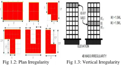
In Plan Irregularity, refer to discontinuous geometric configuration and horizontal resisting elements like diaphagrams, lager opening, out cuts, re-entrant corners, etc. and induced torsion in structure. The elements that are responsible for vertical irregularity forms in the structure are stiffness, mass, geometry, strength, etc. The solution to this problem, the lateral resisting member like the shear wall, bracing, etc. are inserted in the structure to resist lateral forces.
Shear wall is especially important in high rise building which resists wind load and seismic loads. Bracing is a frame structural member to connected pin joint between the column and beam. Bracing is in the form of steel frame and has various types of sections like single diagonal, double diagonal, X braced and K braced etc.
Fig 1.2: Plan Irregularity Fig 1.3: Vertical Irregularity
3. Objective and Scope
3.1
Scope of Work
Based on the gaps found in the literature review:
• To understand the behaviour of structure considering both horizontal irregularity and vertical irregularity in the model.
• The carry out a comparative study of centre located shear wall and single diagonal bracing used in structure.
• To calculate various structural parameters like storey displacement, story shear, storey drift and torsional irregularity.
3.2 Objective of Work
The main objective of work to reduced torsion irregularity in a structure under seismic loads. Also to study the effect of both horizontal and vertical irregularity in the structure model during earthquake loading acts. The following points were studied.
1. Analysis of G+20 storied RC framed structure having both irregularities under the seismic loads.
2. To prepare model having horizontal and vertical irregularity which will be analyzed with centre located shear wall and single diagonal bracing.
3. To evaluate the performance of the model by Response spectrum Analysis by using ETAB software.
4. To obtained result in various structural parameters like story displacement, story shear, story drift and torsional irregularity for each floor level.
4. Methodology
The response spectrum is a linear dynamic analysis method to evaluate of maximum responses related to acceleration, velocity and displacement under performance of ground motion. The response spectrum analysis method is useful for approximate evaluation of seismic reliability of the structure. This method being time consuming and tedious process and it is computer based application. The analysis is carried out on the ETAB 2015 software name as “Extended 3D Analysis of Building Structure” Software.
5. Problem Statement
Fig 5.1: Typical floor Plan
In this present study, the structures have both horizontal irregularity and vertical irregularity. Consider G+20 storied building structures with the irregularity of mass, shape, dimensions and structural properties. The solution to this problem to use structural member place in a model like shear wall and bracing. In this study consider three models having the same dimensional properties of building G+20 with height 63m.
Model 1 – Frame Structure Model 2 – With Shear Wall
Model 3 – With Single Diagonal Bracing Plan Dimension: 26m X 17m
Column size: 300mm X 800mm, 300mm X 700mm, 300mm X 600mm Beam size: 300mm X 600mm, 300mm X 500mm, 300mm X 450mm Grade of Concrete: M30 for column, M25 for beam
Grade of Steel: Fe415 Soil Type: Medium (Type II) Type of Zone: Zone V
Following are the building load configurations as per IS 875 Part 1, 2:1987 shown in Table 5.1.
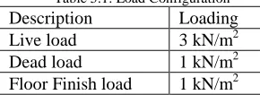
Table 5.1: Load Configuration
Description Loading
Live load 3 kN/m2
Dead load 1 kN/m2
Floor Finish load 1 kN/m2 Followings are the primary load cases considered for the analysis of building:
• Dead Load
• Live Load
• Floor Finish Load
• Earthquake load in the X- direction
6. Results
The Response Spectrum Analysis is carried out using ETAB software. The results are obtained in the various parameters like storey displacement, drift, shear and torsional irregularity which are being presented below in graphical form.
6.1 Storey Displacement
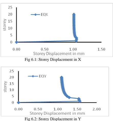
-Model 1Fig 6.1: Storey Displacement in X
Fig 6.2: Storey Displacement in Y
From the above figures for Storey displacement in model 1 are 1.0618mm and 1.5644mm in X and Y direction respectively.
- Model 2
Fig 6.3: Storey Displacement in X
Fig 6.4: Storey Displacement in Y
From the above figures for Storey displacement in model 2 is 1.0373mm about X direction and 1.7516mm in Y direction. Compare with model 1 of 2.31% reduction of displacement in the X direction and 12% in the Y direction.
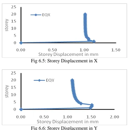
Fig 6.5: Storey Displacement in X
Fig 6.6: Storey Displacement in Y
From the above figures for Storey displacement in model 3 is 1.1517mm about X direction and for displacement of 1.5146mm in Y direction. Compare with model 1 of 8.46% and 3.18% reduction of displacement in X and Y direction respectively.
6.2 Storey Drift
-Model 1
Fig 6.7: Storey Drift in X
Fig 6.8: Storey Drift in Y
Model 2
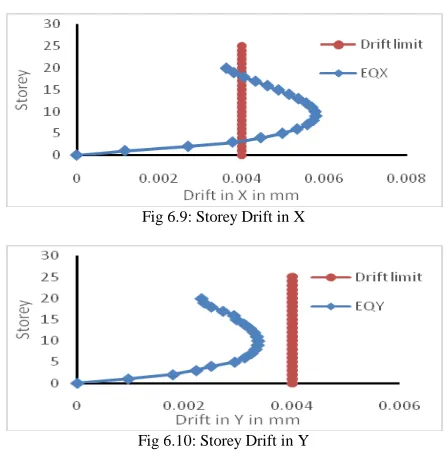
Fig 6.9: Storey Drift in X
Fig 6.10: Storey Drift in Y
From figure 6.9 for Storey drift in model 2 is 0.0058mm about X direction and from figure 6.10 for a drift of 0.0034mm in Y direction. Compare with model 1 of 33.33% and 8.11% reduction of drift in X and Y direction respectively.
-Model 3
Fig 6.10: Storey Drift in X
Fig 6.11: Storey Drift in Y
From the above figures for Storey drift in model 3 is 0.0084mm and 0.0037mm about X and Y direction respectively. Compare with model 1 of 3.44% reduction of drift in the X direction. No reduction of drift in the Y direction when compared with model 1.
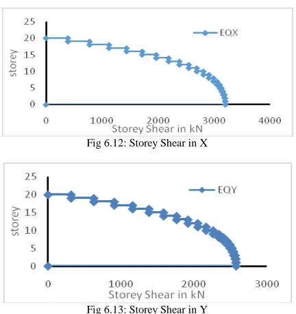
Fig 6.12: Storey Shear in X
Fig 6.13: Storey Shear in Y
From the above figures for Storey shear in model 1 is 3201.33kN and 2579.62kN about X and Y direction respectively. -Model 2
Fig 6.14: Storey Shear in X
Fig 6.15: Storey Shear in Y
From the above figures for Storey shear in model 2 is 3468.18kN and 2794.65kN about X and Y direction respectively. Storey shear reduced by 8% in the X direction and 8.33% in the Y direction when compared with model 1.
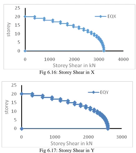
Fig 6.16: Storey Shear in X
Fig 6.17: Storey Shear in Y
From the above figures for Storey shear in model 3 is 3205.60kN and 2583.08kN about X and Y direction respectively. Storey shear reduced by 0.13% in X and Y direction when compared with model 1.
6.4 Torsional Irregularity
-Model 1Fig 6.18: Torsional Irregularity in X and Y direction
From figure 6.18 shows Torsional Irregularity in model 1 of 1.1320 ratios in the X direction and 3.660 ratios in the Y direction.
-Model 2
Fig 6.19: Torsional Irregularity in X and Y direction
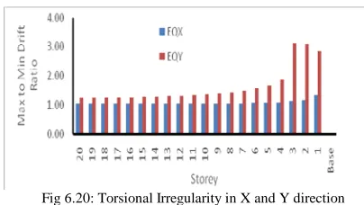
-Model 3
Fig 6.20: Torsional Irregularity in X and Y direction
From figure 6.20 shows Torsional Irregularity in model 3 of 1.3300 drift ratio in the X direction and 3.1140 drift ratios in the Y direction. Torsional irregularity result compares with model 1 reduced by 18% and 5% in X and Y direction respectively.
7. Conclusions
Based on result and discussion the following conclusion is made:
• The storey displacement is reduced when the shear wall used as lateral resisting member in the structure. It gives good result compared with the bracing system.
• Similarly, the small 8.47% reductions in storey shear are observed when lateral resisting member like a shear wall and bracing is used in a structure system.
• The torsional irregularity is reduced by providing the shear wall and bracing to resist lateral earthquake force.
References
1. Shi Qun Guo, “Analysis on Seismic Behaviour of Irregular High-Rise RC Structure using Eccentrically Braces” Advanced Materials Research, Volume 243-249, 2011.
2. Ravikumar C M, Babu Narayan K S, Sujith B V, Venkat Reddy D, “Effect of Irregular configurations on Seismic Vulnerability of RC Buildings” Architecture Research, 2(3):20-26, 2012.
3. P.P Chandurkar, Dr.P.S. Paigade, “Seismic Analysis of RCC Building with and without Shear Wall” International Journal of Modern Engg. Research (IJMER), Volume 3, Issue 3, PP-1805-1810, ISSN-2249-6645, May-June 2013.
4. Manoj Kumar, Dr.Venkata G Babu, “Comparative Study of Seismic Performance of Building having Mass Vertical Irregularity at Different Floor Levels” International Journal of Science and Research (IJSR), ISSN-2319-7064, 2013.
5. H. Gokdemir, “Effects of Torsional Irregularity to a Structure during Earthquakes” ELSEVIER, 2013.
6. Gunay Ozmen, Konuralp Girgin, Yavuz Durgun, “Torsional irregularity in Multi-Storey Structures” Adv Structural Engg 6:121:131, 2014.
7. Milind V. Mohod, “Pushover Analysis of Structures with Plan Irregularity” IOSR Journal of Civil Engg, Volume-12, Issue 4,ver VII, July-Aug 2015.
8. Rajalakshmi K R, Harinrayanan S, “Study of Torsion Effects on Building Structures having Mass and Stiffness Irregularities” ISSN-2278-0181, Volume 4, Issue 06, June-2015.
9. R.B Ghodke, “Torsional Effect for Unsymmetrical R.C. Frames” Volume 03, Issue 07, July-2016.
10. Rahila Thaskeen, Shinu Shajee, “Torsional Irregularity of Multi-storey Structures” Volume 5, Issue 9, Sept-2016.
11. Nandini K. G, Pranathi Reddy B, “Study of Torsional Irregularity in Irregular Structure Provided with Lead Rubber Bearing Isolator” Volume 7, Issue no.6, 2017.
12. Kiran Y, Ashwini G, “Parametric Study on Seismic Vulnerability of Plan Irregular RC Building Considering Torsional Effects” ISSN-2455-1457, Volume 03, Issue 07, July-2017.
13. Shaik Muneer Hussain, “Study on Torsional Effects of Irregular Buildings under Seismic Loads” ISSN-0973-4562, Volume 13, No.7, 2018.
14. Md. Mahmud Sazzad, “Effects of Vertical Irregularity in Steel Braced Frames on Response to Earthquake” Journal of civil Engineering and Architecture 12, 2018.
I.S. Codes
16. IS1893(Part-1):2002, Criteria for Earthquake Resistant Design of Structures, General Provisions and Buildings (Fifth Revision). 17. IS:456-2000, “Code of Practice for Plain and Reinforced Concrete”, Bureau of Indian Standard, New Delhi, India.
18. Indian Standard IS800:2007, “General Construction in Steel-Code of Practice (Third Revision)”, BIS New Delhi. 19. IS1893 (Part-1):2016, Criteria for Earthquake Resistant Design of Structures, General Provisions and Buildings.
Swati J. More P.G Student of B. R. Harne College of Engineering and Technology, Mumbai University.
Dr. Vikram A. Patil Principal and Guide of B. R. Harne College of Engineering and Technology, Mumbai University completed his PhD in Structural Engineering from IIT-Roorkee.