HARMONIC SUPPRESSION OF PARALLEL COUPLED MICROSTRIP LINE BANDPASS FILTER USING CSRR
S. S. Karthikeyan and R. S. Kshetrimayum
Department of Electronics and Communication Engineering Indian Institute of Technology Guwahati
Assam 781039, India
Abstract—Bandstop filter (BSF) is first constructed using open stubs and spurline. The stop bandwidth of this conventional structure is further increased by placing a complementary split ring resonator (CSRR) exactly below the 50 Ω microstrip line. By embedding this BSF with a wide rejection band in the input port of the PCML bandpass filter, unwanted passbands of bandpass filter is eliminated. To demonstrate this, we have designed, fabricated and tested a first order Chebyshev bandpass filter centered at 0.9 GHz with 10% fractional bandwidth (FBW). This bandpass filter is cascaded with the newly proposed BSF. Simulation and measured results shows a harmonic rejection upto 5f0 with more than 20 dB rejection level.
1. INTRODUCTION
Microstrip bandpass filters (BPF) have been widely employed in microwave and wireless communication systems for permitting signal in the desired range of frequencies and rejecting all other. There are different filters techniques available for designing bandpass filters. Parallel coupled microstrip line (PCML) filter is the common one because of its planar structure, readily available design formulae and easy design procedures. But the fundamental limitation of such BPFs is the presence of nearby out-of-band spurious passbands. This is mainly due to difference in the odd and even mode phase velocities and distributed nature of microstrip line. To obtain the symmetric passband response these spurious passbands should be completely removed or suppressed.
removed in [1]. In [2], continuous perturbation of the coupled line width according to sinusoidal law has been suggested for suppressing the second harmonic. Corrugated coupled microstrip lines are designed to equalize the odd and even mode phase velocities for obtaining wide upper stop band in [3]. Based on Bragg reflection, periodic grooves are etched in the microstrip lines to eliminate spurious passband at 2f0 [4]. Split ring resonators (SRR) and complementary split ring resonators (CSRR) have been established as a means for suppression of harmonics in microstrip and CPW technologies [5, 6]. Bandstop filter using open stub and spurline can be adopted for suppressing second harmonic in the open loop ring band pass filter [7]. Odd and even mode phase velocities were made equal using substrate suspension technique [8] and placing dielectric overlay over coupled lines [9] to eliminate the second harmonic. Parallel coupled microstrip sections with a slotted ground plane are proposed as building blocks of PCML bandpass filters for harmonic rejection in [10]. Floating strip conductors printed on the backside of the substrate are shown to be useful for suppressing second harmonics in microstrip filters [11].
But the use of PBG structures for low frequencies increase the circuit area of the filter and side by side introduce the pass band ripples. As SRRs are normally placed on the upper side of the substrate close to the signal strip, it results in the increased filter size. The printing of sinusoidal and corrugated structures as the signal strip is bit difficult in fabrication process. In this paper, to reject the unwanted spurious passband, we are using traditional open stub-spurline rejection band filter. But to enhance the rejection bandwidth, additional transmission zeros are introduced by placing a CSRR under the 50 Ω microstrip line. Using this newly proposed bandstop filter (BSF), which is constructed employing three BSFs, harmonic suppression of PCML BPF upto fifth order harmonic (5f0) is possible. It is demonstrated both from IE3D simulation results as well as experimental results.
2. DESIGN OF WIDE BANDSTOP FILTER USING CSRR
(b)
l
d g
Ground plane
c
2r
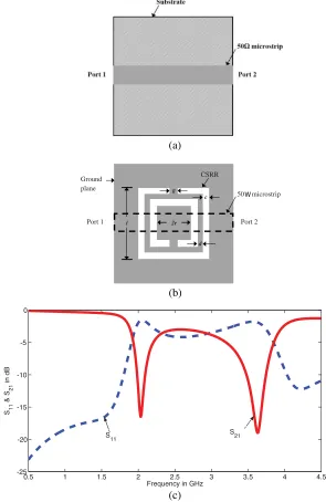
50 microstrip
Port 1 Port 2
CSRR
W
0.5 1 1.5 2 2.5 3 3.5 4 4.5
-25 -20 -15 -10 -5 0
Frequency in GHz
S11
& S
21
in dB
S11 S21
(a)
(c)
with the help of device dimensions: l,c,d, and g [12].
We have designed a CSRR to resonate at 2 GHz withl= 10 mm,
c= 0.5 mm,d= 0.5 mm,r = 3.5 mm, andg= 0.5 mm. This structure is placed in the ground plane exactly below the 50 Ω microstrip line. For all the simulations, FR4 dielectric substrate of εr = 4.4 and height 1.6 mm is used and the filters are simulated using full-wave electromagnetic simulator Zeland IE3D software [13]. Fig. 1(c) shows the simulation results of the CSRR. Two attenuation poles appear around 2 GHz and 3.6 GHz. Stop bandwidth of the designed CSRR loaded microstrip line bandstop filter is only 100 MHz.
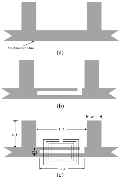
Conventional open stub filter is constructed by placing two open stubs of length L1 = λg/4 at a distance of L2 =λg/4 on a microstip line, where λg is the guided wave length. We have designed the open stub filter at the center frequency of 4 GHz. The optimized dimensions for the filter are L1 = 10.23 mm, L2 = 10.23 mm, andW1 = 3.06 mm.
50 Microstrip line
L 3
W 2
L 2 L 1
W 1
(a)
(b)
(c)
Ω
1.5 2 2.5 3 3.5 4 4.5 5 -50
-45 -40 -35 -30 -25 -20 -15 -10 -5 0
Frequency in GHz
S21
in dB Proposed
Open stub
Open stubSpurline
Figure 3. Simulated insertion loss of various BSFs.
This filter gives a stop bandwidth of 1.35 GHz. A wide stopband can be obtained by cascading more number of open stubs but it results in increased device area. To overcome this limitation, spurline is embedded [7] between the open stubs. The length of the spurline is
λg/4 and width is chosen as 30% of the microstrip line width. The optimized dimensions of spur line are L3 = 10 mm and W2 = 1 mm. The stop bandwidth of stub-spurline filter is 2 GHz, which is 0.65 GHz more than open stub BSF. To extend the rejection bandwidth further, two attenuation poles are introduced by placing a CSRR below the open stub and spurline section. Due to this, stopband of the bandstop filter is enhanced upto 2.93 GHz. Fig. 2 and Fig. 3 shows the various types of bandstop filter layouts and their simulated insertion losses respectively. Among them, CSRR-Stub-Spurline filter has the widest stop bandwidth and sharp passband to stopband transition compared to other BSFs. Stop bandwidths of various BSFs are listed in Table 1.
Table 1. Comparison of three BSFs.
Filter Type Stop bandwidth in GHz
Open stub 1.35
Open Stub-Spurline 2
3. HARMONIC SUPPRESSION OF PCML BPF
To demonstrate the harmonic rejection capabilities of the proposed bandstop filter, a first order Chebyshev parallel coupled microstrip line bandpass filter centered atfc = 0.9 GHz with 10% fractional bandwith (FBW) has been designed on FR4 substrate using the standard design procedure [14, 15]. The physical parameters of the filter are listed in Table 2.
Table 2. Physical parameters of the first order Chebychev BPF centerd at 0.9 GHz with 10% FBW.
i Z0eΩ Z0oΩ wi(mm) si(mm) li(mm)
1 70 30 1.22 0.512 46.972
(a)
(b)
1 1.5 2 2.5 3 3.5 4
Frequency in GHz
Measured S11
Simulated S12 Simulated S11
Measured S12
0.5 1 1.5 2 2.5 3 3.5 4 4.5
-60 -50 -40 -30 -20 -10 0
Frequency in GHz
S11
& S
21
in dB Simulated S11
Simulated S21
Measured S21
Measured S11
Figure 4(a) shows the photograph of conventional fabricated filter. Simulated and measured scattering parameters (S11 and S12) of the filter are shown in Fig. 4(b). Here we observe that the spurious passbands occur at multiples of the center frequency. This spurious passband will degrade the filter performance. So by embedding the proposed wide rejection bandwidth bandstop filter in the input port of the PCML bandpass filter, these harmonics can be effectively eliminated.
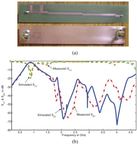
Figure 5(a) illustrates the photograph of new harmonic suppressed PCML BPF. Fig. 5(b) shows the simulated and measured results of the proposed PCML bandpass filter with CSRR-Stub-Spurline section. The measured insertion and return loss are less than−1.43 dB and −20 dB respectively. The rejection level is more than −20 dB upto 4.5 GHz, that means, harmonic suppression up to 5f0 has been
(a)
(b)
0.5 1 1.5 2 2.5 3 3.5 4 4.5
-80 -70 -60 -50 -40 -30 -20 -10 0
Frequency in GHz S11
& S
21
in dB
Simulated S 21 Simulated S
11
Measured S11
Measured S 21
achieved. Above 30 dB rejection level is obtained from 3 to 4.2 GHz. The little differences in the simulated and experimental results is due to the tolerances in the fabrication process.
4. CONCLUSION
New bandstop filter is constructed using CSRR, Open stub and Spurline. It produces sharp passband to stopband transition and 47% more rejection bandwidth than the conventional BSF assuring the same device area. By combining this BSF with conventional parallel-coupled line bandpass filter, the undesired harmonics are eliminated. The proposed harmonic suppressed PCML bandpass filter offers more than 20 dB rjection level upto the fifth harmonic, maximum rejection level of 75 dB in the stop band and low passband insertion loss of 1.43 dB.
ACKNOWLEDGMENT
Authors are grateful to Science and Engineering Research Council, Department of Science and Technology, India for supporting this study (Project No: ECE/P/KRS/01/DST).
REFERENCES
1. Yang, F. R., K. P. Ma, Y. Qian, and T. Itoh, “A uniplanar compact photonic-bandgap (UC-PBG) structure and its applications for microwave circuits,” IEEE Trans. Microwave Theory Tech., Vol. 47, No. 8, 1509–1514, 1999.
2. Lopetegi, T., M. A. G. Laso, J. Hernandez, M. Bacaicoa, D. Benito, M. J. Garde, M. Sorolla, and M. Guglielmi, “New microstrip “wiggly-line” filters with spurious passband suppression,”IEEE Trans. Microw. Theory Tech., Vol. 49, No. 9, 1593–1598, 2001.
3. Kuo, J.-T., W.-H. Hsu, and W.-T. Huang, “Parallel coupled microstrip filters with suppression of harmonic response,” IEEE Microwave Wireless Compon. Lett., Vol. 12, No. 10, 383–385, 2002.
4. Kim, B. S., J. W. Lee, and M. S. Song, “An implementation of harmonic-suppression microstrip filters with periodic grooves,”
5. Garcia, J., F. Martin, F. Falcone, J. Bonache, I. Gil, T. Lopetegi, M. A. G. Laso, M. Sorolla, and R. Marques, “Spurious passband suppression in microstrip coupled line band pass filters by means of split ring resonators,”IEEE Microwave Wireless Compon. Lett., Vol. 14, No. 9, 416–418, 2004.
6. Garcia, J., F. Martin, F. Falcone, J. Bonache, J. D. Baena, I. Gil, E. Amat, T. Lopetegi, M. A. G. Laso, J. A. M. Iturmendi, M. Sorolla, and R. Marques, “Microwave filters with improved stopband based on sub-wavelength resonators,” IEEE Trans. Microw. Theory Tech.,Vol. 53, No. 6, 1997–2004, 2005.
7. Tu, W.-H. and K. Chang, “Compact microstrip bandstop filter using open stub and spurline,” IEEE Microwave Wireless Compon. Lett., Vol. 15, No. 4, 268–270, 2005.
8. Kuo, J.-T., M. Jiang, and H.-J. Chang, “Design of parallel-coupled microstrip filters with suppression of spurious resonances using substrate suspension,”IEEE Trans. Microw. Theory Tech., Vol. 52, No. 1, 83–89, 2004.
9. Kuo, J.-T. and M. Jiang, “Enhanced microstrip filter design with a uniform overlay for suppressing the second harmonic response,”
IEEE Microwave Wireless Compon. Lett., Vol. 14, No. 9, 419–421, 2004.
10. Ahumada, M. C. V., J. Martel, and F. Medina, “Parallel coupled microstrip filters with ground-plane aperture for spurious band suppression and enhanced coupling,”IEEE Trans. Microw. Theory Tech., Vol. 52, No. 3, 1082–1086, 2004.
11. Ahumada, M. C. V., J. Martel, and F. Medina, “Parallel coupled microstrip filters with floating ground-plane conductor for spurious band suppression,” IEEE Trans. Microw. Theory Tech., Vol. 53, No. 5, 1823–1828, 2005.
12. Bian, W., B. Li, T. Su, and C.-H. Liang, “Study on transmission characteristic of split-ring resonator defected ground structure,”
PIERS Online, Vol. 2, No. 6, 710–713, 2006. 13. IE3D, version 10.2, Zeland Corp, Freemont, CA.
14. Matthaei, G. L., L. Young, and E. M. T. Jones,Microwave Filters, Impedance-Matching Networks and Coupling Structures, Artech, 1980.