MICROSTRIP ANTENNA USING GROUND-CUT
SLOTS FOR LOW RCS WITH SIZE MINIATURIZATION TECHNIQUES
Y. Li, Y. Liu, and S. Gong
National Laboratory of Antennas and Microwave Technology Xidian University
Xi’an 710071, Shaanxi, China
Abstract—The techniques of ground-cut slots and miniaturization are applied in the design of microstrip antenna which reduces the resonance frequency and size of antenna and achieves the Radar Cross Section (RCS) reduction. Compared with the rectangular patch antenna working at the same frequency, the designed antenna realizes the RCS reduction in the whole frequency band of 2–8 GHz. And the RCS can be reduced 2–4 dB at its working frequency. The RCSpeaks are efficiently controlled to get a smooth curve while the gain loss is only approximately 0.9 dB, which assures the radiation performance. The measured results of radiation performance accord with the simulation results and it implies that this method is feasible.
1. INTRODUCTION
certain application: large radar cross section (RCS) at the resonant frequencies [4, 5].
Although it is supposed to reduce the RCSof microstrip patch antenna arrays in most practical applications, the RCSof patch arrays at resonance is much larger than their respective cross-sectional areas because of the RCSof single microstrip patch [6]. So it is necessary to obtain a single microstrip patch antenna with low RCSfirst. There are many methods currently available to reduce the RCSof single microstrip patch antennas. In contrast, research on the RCSreduction of array is reported little. Researchers have devised several methods to reduce the RCSof single microstrip patch. Distributed loading has been used to suppress the patch RCSwhile having a minimal effect at the operational frequency of the patch [7]. By controlling the bias voltage across a varactor diode that is mounted between the patch and ground plane, the scattering response of the antenna can be tuned to minimize the RCSat threatened frequencies [8]. The RCSpeaks of a microstrip patch antenna printed on a ferrite substrate can be shifted by changing the magnetic bias field with little effect upon the radiation property of microstrip antennas [9]. Additionally, the application of meshed patch antennas to the RCSreduction of microstrip antennas has been investigated yet being at the cost of the gain and bandwidth of the antenna [10]. In conclusion, the RCSreduction of single microstrip patch, which is a problem that has not yet been satisfactorily solved, requires further research.
To reduce the RCSof antenna, changing the shape of patch which minimizes the patch and making slots in the ground plane are proposed in this letter. With the radiation performance almost maintained, a low RCSantenna is designed.
2. THE THEORY OF RCS REDUCTION
The total scattering field of antennas constitutes structural scattering and antenna-mode scattering. When the feed port is match loaded, the scattering is structural scattering. If not, part of the received energy is reradiated, which is antenna mode scattering [11].
10mm
13
.5m
m
32mm
17
m
m
18mm
39.
5
m
m
x
y
z
Figure 1. Configuration of the proposed patch.
The techniques of slots-cutting can change the radiation and impedance property of microstrip antenna, which has been used in broad up the bandwidth of antenna [13–15]. Considering the radiation and scattering property, we design the patch with slots in the ground plane as shown in Fig. 2. In additional, the size of ground plane can also affect the scattering property of antenna, so the ground plane should be designed as small as possible on the premise that the construction and radiation property of antenna remain.
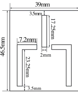
39mm
46.
5m
m
2mm
17.
25m
m
3.5mm
7.2mm
23
.2
5
m
m
3.5mm
3. ANTENNA CONFIGURATION AND RESULTS
The techniques of ground-cut slots and miniaturization are applied in the design of microstrip antenna, and we will get a patch antenna with low RCS. The antenna substrate is 2 mm thick and with the relative permittivity εr = 2.6. Antenna is fed by coaxial line with 50 ohm in the position of (3.7, 0, 0). The working frequency of the antenna is 2.29 GHz. The configuration of patch and size of slots in the ground plane are shown in Figs. 1 and 2, and Fig. 3(a) and (b) give the pictures of patch and ground plane. For comparative purpose, a rectangular patch antenna with the same resonant frequency is also designed as the standard antenna. The size of rectangular patch antenna is 37×47.4mm2, and the thickness and the relative permittivity of the dielectric substrate are the same with those of the proposed antenna. It can be seen that the area of this novel patch is 62.3% smaller than the rectangular patch antenna.
(a)
(b)
Figure 3. Photographs of the proposed antenna.
2.20 2.25 2.30 2.35 2.40 -25
-20 -15 -10 -5 0
S11(dB)
Frequency(GHz)
Measured standard antenna Measured proposed antenna Simulated standard antenna Simulated proposed antenna
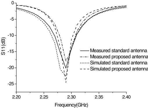
Figure 4. Simulated and measured S11 of two antennas.
the simulated bandwidth has a loss of 0.7%. There is a frequency shift, which may be caused by the fabrication error. The measured bandwidth loss is almost the same with the simulated results.
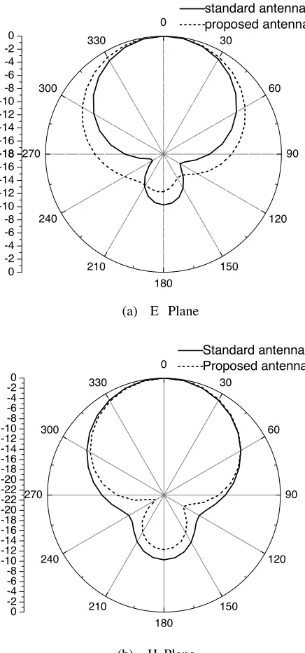
The simulated and measured radiation patterns of ϕ = 0◦ and
ϕ= 90◦of two antennas are shown in Fig. 5 and Fig. 6. The simulated gain at the resonant frequency decreases from 6.65 dB to 5.72 dB. The measured gain of the proposed antenna has a loss of 0.5 dB, which is better than simulated results. From the simulated results, we can see that back lobe of the proposed antenna become smaller than the standard antenna. The miniaturization brings little changes to the radiation ability.
The comparisons of RCSbetween the standard antenna and the proposed antenna are given in Fig. 7. The incidence angles areθ= 60◦,
0 30 60 90 120 150 180 210 240 270 300 330 -18 -16 -14 -12 -10 -8 -6 -4 -2 0 -18 -16 -14 -12 -10 -8 -6 -4 -2 0 standard antenna proposed antenna
(a) E Plane
0 30 60 90 120 150 180 210 240 270 300 330 -22 -20 -18 -16 -14 -12 -10-8 -6 -4 -20 -22 -20 -18 -16 -14 -12 -10 -8 -6 -4 -2 0 Standard antenna Proposed antenna
(b) H Plane
0
30
60
90
120
150 180
210 240 270
300 330
-25 -20 -15 -10 -5 0
-20
-15
-10
-5
0
standard antenna proposed antenna
(a) E Plane
0
30
60
90
120
150 180
210 240 270
300 330
-35 -30 -25 -20 -15 -10 -5 0
-30 -25 -20 -15 -10 -5 0
standard antenna proposed antenna
(b) H Plane
2 3 4 5 6 7 8 -42
-40 -38 -36 -34 -32 -30 -28 -26 -24 -22
RCS(dBsm)
Frequency (GHz)
standard antenna proposed antenna
(a)
2 3 4 5 6 7 8
-38 -36 -34 -32 -30 -28 -26 -24 -22 -20
RC
S
(dB
s
m
)
Frequency(GHz)
standard antenna proposed antenna
(c)
2 3 4 5 6 7 8
-50 -45 -40 -35 -30 -25 -20 -15
RCS
(d
B
s
m)
Frequency(GHz)
standard antenna proposed antenna
Figure 7. Simulated RCS of two antennas. (a)θ= 60◦,ϕ= 45◦, (b)
θ= 60◦,ϕ= 0◦, (c) θ= 60◦,ϕ= 90◦.
4. CONCLUSION
The RCSreduction mechanism of microstrip antenna using ground-cut slots and miniaturization techniques is analyzed in the paper, and microstrip antenna with low RCSand good radiation ability is designed and measured. Considering the machining precision and measure error, the proposed method works when there is little influence of the radiation ability. The proposed antenna can be conveniently used as microstrip antennas where low RCSproperty is required.
REFERENCES
1. Sayem, A. M. and M. Ali, “Characteristics of a microstrip-fed miniature printed hilbert slot antenna,” Progress In Electromagnetics Research, PIER 56, 1–18, 2006.
3. Donelli, M., S. Caorsi, F. DeNatale, M. Pastorino, and A. Massa, “Linear antenna synthesis with a hybrid genetic algorithm,” Progress In Electromagnetics Research, PIER 49, 1–22, 2004. 4. Newman, H., “Scattering from a microstrip patch,” IEEE
Transaction on Antenna and Propagation, Vol. AP-35, No. 3, 245– 251, March 1987.
5. Pozar, D. M., “Radiation and scattering from a microstrip patch on a uniaxial substrate,” IEEE Transaction on Antenna and Propagation, Vol. AP-35, No. 6, 613–621, June 1987.
6. King, A. S., “Scattering from a finite array of microstrip patches,” IEEE Transaction on Antenna and Propagation, Vol. AP-40, No. 7, 770–774, 1992.
7. Volakis, J. L., A. Alexanian, and J. M. Lin, “Broadband RCS reduction of rectangular patch by using distributed loading,” Electron Lett., Vol. 28, No. 25, 2322–2323, 1992.
8. Aberle, J. T., M. Chu, and C. R. Birtcher, “Scattering and radiation properties of varactor-tuned microstrip antennas,” Antennas Propagat. Soc. Int. Symp. Dig., Vol. 4, 2229–2232, 1992. 9. Pozar, D. M., “Radiation and scattering characteristics of microstrip antennas on normally biased ferrite substrates,”IEEE Trans. Antennas Propagation, Vol. AP-40, No. 9, 1084–1092, 1992. 10. Wu, B.-I., W. Wang, J. Pacheco, X. Chen, T. M. Grzegorczyk, and J. A. Kong, “A study of using metamaterials as antenna substrate to enhance gain,” Progress In Electromagnetics Research, PIER 51, 295–328, 2005.
11. Liu, Y., S. Gong, H. Guo, and D. Fu, “Fractal microstrip patch antenna for antenna RCSreduction,” Acta Electronica Sinica, Vol. 32, 1530–1531, 2004.
12. He, X., S. Gong, Y. Ji, and Q. Liu, “Meshed microstrip patch antennas with low RCS,” Microwave and Optical Technology Letters, Vol. 46, 117–120, 2006.
13. Wan, J. X. and C.-H. Liang, “A fast analysis of scattering from microstrip antennas over a wide band,” Progress In Electromagnetics Research, PIER 50, 187–208, 2005.
14. Saed, M. A., “Broadband cpw-few planar slot antennas with various tuning stubs,” Progress In Electromagnetics Research, PIER 66, 199–212, 2006.