Simulation of PI with Fuzzy Logic Controller
Based Dynamic Voltage Restorer as Voltage
Sag Restorer in Distribution System
K. Vijaya Bhaskar
1, K. Satish
2Assistant Professor, Dept. of EEE, SVPCET, Puttur, Andhra Pradesh, India1
PG Student [EPS], Dept. of EEE, SVPCET, Puttur, Andhra Pradesh, India2
ABSTRACT: Distribution system needs to be protected against voltage sags, dips & swells that adversely affect the reliability & quality of power supply at the utility end. These problems can be mitigated with voltage injection method using custom power device, Dynamic Voltage Restorer (DVR). In this paper we design a Dynamic Voltage Restorer (DVR) which is utilized for power quality improvement. Here we propose two control techniques which are the Proportional Integral (PI) Controller and Fuzzy Logic (FL) Controller. The proposed DVR employs the classical Fourier Transform (FT) for sag/swell detection and quantification and a Fuzzy Logic based feedback controller which utilizes the error signal (difference between the reference voltage and actual measured load voltage) to control the triggering of the switches of an inverter using a Sinusoidal Pulse Width Modulation (SPWM) scheme. The proposed DVR utilizes the energy from available supply line feeders through a rectifier to feed the inverter. Modelling and simulation of the proposed DVR is implemented in MATLAB/SIMULINK platform. Over all the DVR is improving the voltage quality as well as the reactive power demand during the uncharacteristic condition.
KEYWORDS:Dynamic voltage Restorer (DVR), Voltage sag, THD, PI with Fuzzy Logic Controller, Pulse Width Modulation (PWM).
I.INTRODUCTION
Two of the main problems in the field of power quality are voltage sag and instantaneous power loss. In addition, voltage sag has two main parameters including magnitude and time duration. Typically, DVR voltage injection method is used to compensate the difference between voltage when sag occurs and when before sag occurs, using AC voltage in series. Another method is to inject voltage in phase with supply voltage when sag occurs. The advantage of both methods is that it uses economical energy storage, yet it has disadvantage of the occurrence of phase shift. Conventional fuzzy logic controller can reduce the time needs; however this controller needs many membership functions. Some researchers have been done to decrease the number of membership functions.
controller which drives the plant to be controlled with a weighted sum of the error (difference between output and desired set-point) and the integral of that value.
A new fuzzy logic (FL) method has been applied to custom power devices, especially for active power filters. The operation of DVR is similar to that of active power filters in that both compensators must respond very fast on the request from abruptly changing reference signals. In the literature, FL control of DVR based on dq Synchronous Reference Frame (SRF). In three-phase supply voltages are transformed into d and q coordinates. The reference values for Vd and Vq are compared with these transformed values and then voltage errors are obtained. FL controllers evaluating linguistic rules process these errors. Resulting outputs are retransformed into three-phase domain and compared with a carrier signal to generate PWM inverter signals. This paper presents the modeling and simulation of a PI with FLC-based DVR under voltage sag phenomena. In this case, the PI with fuzzy logic controller has been incorporated instead of conventional other controller. The simulation tool is the MATLAB/Simulink Power System Block set (PSB). The capability of DVR to mitigate the voltage sag is demonstrated by MATLAB simulation. The addition of PI with fuzzy logic control to gives added advantage of faster response as compared to the conventional one. A PI controller with a linear structure offers satisfactory performance over a widerange of operation [4] . The problem encountered by the controller is the setting of PI parameters i.e. the gains (Kp,Ki). In the influence of varying parameters and operating conditions, the fixed gains of linear controller don’t adaptaccordingly to give good dynamic response. To overcome the problems faced by a linear technique, non-lineartechnique is an effective solution [5]. The recommended system uses the PI, Fuzzy [6][7][8] and Hybrid Fuzzy-PI[9] logic controllers to investigate the performance level of various controllers in a regard to increase the capabilityof the existing system by creating immunity from disturbances. Simulation results of voltage sag condition for alinear & non-linear load are presented.
II. POWER QUALITY PROBLEMS
Power quality means the fitness of electrical power and its stabilized disposition to power consumer device. PQ problem is defined as any problem manifested in voltage, current or a frequency deviation that leads to the failure or disoperation of consumer equipment. Power quality is not a single unit measurement it is a collection of several type which includes Capacitor switching, lightning surge (Transient), Interruptions, Sags/Swells (Disturbance), Harmonics, Flicker, Voltage regulation, Reliability, Power factor (Steady-state). There are several types of power quality problems that a customer may encounter and may classified according or depending on how the voltage waveform is being distorted. There are transients, short duration of variations (sags, swells, and interruption), long duration variations (sustained interruptions, under voltages, over voltages), voltage imbalance, waveform distortion (dc offset, harmonics, inter harmonics, notching, and noise), voltage fluctuations and power frequency variations.
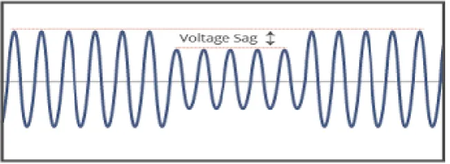
A. Voltage Sags
Voltage sag is defined as the reduction of RMS voltage between 0.1 p.u. and 0.9 p.u. and lasting between 0.5 cycles to 1 minute. Voltage sag are mostly caused by system fault and last for duration ranging from 3 cycles to 30 cycles depending on the fault clearing time.
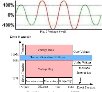
B. Voltage Swells
A voltage swells is defined as a rise in RMS voltage which is between 1.1 p.u and 1.8p.u for period stuck between 0.5 cycles to 1 minute. A voltage swell is characterized by its magnitude (RMS) and duration.
Fig. 2 Voltage Swell
Fig. 3 Voltage reduction standard of IEEE
C. Solutions of Power Quality Problems
In general, there are two come within reach of followed to alleviate the tribulations associated with power quality. First approach is called load training, which guarantees that the equipment is less perceptive to power turbulence permitting the operation still below significant voltage deformation and the second approach is to mount line conditioning schemes that suppress or neutralizes the power schemes turbulences. The procession conditioning system or convenience side solutions will participate a major role in improving the inherent supply quality; some of the effective and economic measures can be identified which are as follows: Lightening and Surge Arresters, Thyristor Based Static Switches, Energy Storage Systems, Harmonic Filters etc.
III.DYNAMIC VOLTAGE RESTORER
The major objectives are to increase the capacity utilization of distribution feeders (by minimizing the RMS values of the line currents for a specified power demand), reduce the losses and improve power quality at the load bus. The major assumption was to neglect the variations in the source voltages. This essentially implies that the dynamics of the source voltage is much slower than the load dynamics.
The voltage source converter is typically one or more converters connected in series to provide the required voltage rating. The DVR can inject a (fundamental frequency) voltage in each phase of required magnitude and phase. The DVR has two operating modes
Standby (also termed as Short Circuit Operation (SCO) mode) where the voltage injected has zero magnitude.
Boost (when the DVR injects a required voltage of appropriate magnitude and phase to restore the pre-fault load bus voltage).
A. Voltage Source Inverter
It forms the building block of compensating device. It performs the power conversion process from DC to AC. VSI consists of fully controlled semiconductor power switches to form a single phase or three phase topologies. For medium power inverters, IGBT’s are used and GTO’s or IGCT’s due to compact size & fast response for high power inverters are employed. The single phase VSI topology encompasses a low-range power applications and medium to high power applications are covered by the three phase topology.
B. Series Injection Transformer
It provides electrical isolation & voltage boost to the system. In a 3-phase system, either 3 single phase units of isolating transformer or 3-phase isolating transformer can be employed for the purpose of voltage injection. Proposed system uses 3 single phase units of isolating transformer with unity turns ratio.
C. Filters
These are electronic circuits comprising of combination of passive elements; resistors, inductors & capacitor.LC type of filters corrects the harmonic output from VSI to provide compensation in the required phase of the 3 phase system boosted by DVR.
Fig.4 Schematic diagram of DVR
D. Energy Storage
This is required to provide active power to the load during deep voltage sags. Lead-acid batteries, flywheel or SMES can be used for energy storage. It is also possible to provide the required power on the DC side of the VSC by an auxiliary bridge converter that is fed from an auxiliary AC supply.
IV.CONTROL TECHNIQUES FOR DVR
The fundamental roles of a controller in a DVR are to detect the voltage sag occurrence in the system; calculate the compensating voltage, to generate trigger pulses of PWM inverter and stop triggering when the occurrence has passed. Using RMS value calculation of the voltage to analyze the sags does not give a fast and accurate result. In this study the dqo transformations or parks transformations is used in voltage calculation. The dqo transformation is a transformation of coordinates from the three phase stationary coordinate system to the dq rotating coordinate system.[8] This dqo method gives the information of the depth (d) and phase shift (q) of voltage sag with start and end time.
𝑉𝑜= 1
3 𝑉𝑎+ 𝑉𝑏+ 𝑉𝑐
𝑉𝑑= 2
3 𝑉𝑎sin ⍵𝑡 + 𝑉𝑏sin(⍵𝑡 − 2𝜋
3) + 𝑉𝑐sin(⍵𝑡 + 2𝜋
3)
𝑉𝑞= 2
3 𝑉𝑎cos ⍵𝑡 + 𝑉𝑏cos(⍵𝑡 − 2𝜋
3) + 𝑉𝑐cos(⍵𝑡 + 2𝜋
After conversion, the three-phase voltage Va, Vb and Vc become two constant voltages Vd and Vq and now, they are easily controlled. In this paper, two control techniques have been proposed which are proportional integral (PI) controller and fuzzy logic (FL) controller.
A. Proportional-Integral Controller
PI Controller is a feedback controller which drives the plant to be controlled with a weighted sum of the error and the integral of that value. The proportional response can be adjusted by multiplying the error by constant KP, called proportional gain. The contribution from integral term is proportional to both the magnitude of error and duration of error. The error is first multiplied by the integral Gain, Ki and then was integrated to give an accumulated offset that have been corrected previously.
B. Fuzzy Logic Controller
Fuzzy logic (FL) controller is one of the most successful operations of fuzzy set theory, its major features are the use of linguistic variables rather than numerical variables. This control technique relies on human capability to understand the systems behavior and is based on quality control rules. Fuzzy Logic provides a simple way to arrive at a definite conclusion based upon vague, ambiguous, imprecise, noisy, or missing input information.
The general structure of an FLC is represented in Figure 5 and comprises of four principal components:
Fig.5 Basic structure of FL controller
A Fuzzyficationinterface which converts input data into suitable linguistic values.
A Knowledge Base which consists of a data base with the necessary linguistic definitions and control rule set.
A Decision Making Logic which, simulating a human decision process, infers the fuzzy control action from the knowledge of the control rules and the linguistic variable definitions and
A Defuzzyfication interface which yields a nonfuzzy control action from an inferred fuzzy control action.
Fig.6 Error as input
Fig.7 Change in Error as input
In the decision-making process, there is rule base that linking between input (error signal) and output signal. Table 1 show the rule base used in this FL controller.
Table.1: Rule base
V. SIMULATION AND RESULTS
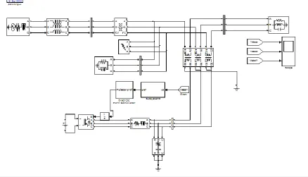
In order to understand the performance of the DVR along with control, a simple distribution network as shown in Fig.9 is implemented. There are different fault conditions like normal system, single line to ground fault, double line to ground fault, three phase fault and voltage sag simulated using MATLAB/SIMULINK software. PI with fuzzy logic controller is used for the control purpose. The DVR system connected to the distribution system using a booster transformer.
Fig.9 Simulink Model of DVR Test System
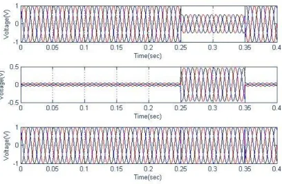
Fig.10 Normal system; (a) Supply voltage, (b) Injection voltage, and (c) Load voltage
Fig.12 Double Line to ground fault; (a) Supply voltage, (b) Injection voltage, and (c) Load voltage
S.no. Condition THD(%)
1 Normal system 0.45
2 Single Line to Ground Fault 0.77
3 Double Line to Ground Fault
0.77
4 Three Phase Fault 0.78
Table.2 Comparison of THD
VI.CONCLUSION
In this paper, the modelling and simulation of DVR controlled by PI with Fuzzy Logic Controller has been developed using Matlab/Simulink. A controller utilizes the error signal which is actually the difference between the reference signal and the actual signal. Voltage source convertor (VSC) was implemented with the help of pulse width modulation. It is fast and simple and finally aFuzzy Logic based feedback controller is used to control the voltage injection of the proposed DVR system in case of voltage disturbances. The proposed DVR utilizes energy drawn from the supply line source during normal operation and stores in capacitors and which is converted to an adjustable three phase ac voltage suitable for mitigation of voltage sags. The main advantages of the proposed DVR are simple and efficient adaptive control and fast response.
REFERENCES
[1] R. H. Salimin and M. S. A. Rahim “Simulation Analysis of DVR Performance for Voltage Sag Mitigation” The 5th International Power Engineering and Optimization Conference (PEOCO2011), Shah Alam, Selangor, Malaysia: 6-7, pp. 261-266, June 2011.
[2] PaisanBoonchiamlPromsakApiratikull and Nadarajah Mithulananthan2“Detailed Analysis of Load Voltage Compensation for Dynamic Voltage Restorers” IEEE Transactions, 2006.
[3] Omar R and Rahim, N.A. “New Control Technique Applied in Dynamic Voltage Restorer for Voltage Sag Mitigation” Industrial Electronics and Applications, 2009. 4th IEEE Conference, pp.848 – 852, ICIEA 2009.
[4] H.P. Tiwari and Sunil Kumar Gupta, Dynamic Voltage Restorer against Voltage Sag, International Journal of Innovation, Management and Technology, Vol. 1, No. 3, August 2010.
[5] A. Teke K. Bayindir and M.Tu¨may“Fast sag/swell detection method for fuzzy logic controlled dynamic voltage restorer” IET Gener. Transm. Distrib., Vol. 4, Iss. 1, pp. 1–12, 2010.
[6] Md. R.Azim, Md. A. Hoque, A Fuzzy Logic based Dynamic Voltage Restorer for Voltage Sag and Swell Mitigation for Industrial Induction Motor Loads, International Journal of Computer Applications, Volume 30– No.8, September 2011.
[7] B.Panda, A.K. Mahapatra, Fuzzy logic controller-based Dynamic voltage restorer for mitigation of voltage sag, International Journal of Engineering Science and Technology, Vol. 3 No. 2 Feb 2011.
[9] S.Ezhilarasan, G.Balasubramanian, Dynamic voltage restorer for voltage sag mitigation using Pi with fuzzy logic controller, International Journal of Engineering Research and Applications, Vol. 3, Issue 1, , pp.1090-1095, January -February 2013.
[10] B.Panda, A.K. Mahapatra and D.P. Bagarty* And S. Behera** “Fuzzy Logic Controller - Based Dynamic Voltage Restorer For Mitigation of Voltage Sag” International Journal of Engineering Science and Technology (IJEST), Vol. 3 No. 2, pp. 996-1007, Feb 2011.
BIOGRAPHY
K. Vijaya Bhaskar1 received B.Tech(EEE) from SVCET,Chittoor Affiliated to JNTU, Anantapur in 2007 and M.Tech(EPE) from SITAMS Affiliated to JNTU, Anantapur in 2010 and he is currently working as Assistant Professor in SVPCET, Puttur, A.P, India.