ISSN (Online): 2278 – 8875
I
nternational
J
ournal of
A
dvanced
R
esearch in
E
lectrical,
E
lectronics and
I
nstrumentation
E
ngineering
(An ISO 3297: 2007 Certified Organization)
Website: www.ijareeie.com
Vol. 6, Issue 12, December 2017
Performance Analysis of DTC, FOC and
their combination applied to Multiple
Induction Motor Drives with FLI
Aadam I. Harnekar1, Anmol A. Welpulwar2, Akshay Ekbote3, Madhavi Nerkar4
UG Student, Department of Electrical Engineering, DVVP COE, Pune University Ahmednagar, Maharashtra, India1,2,3
Professor, Department of Electrical Engineering, DVVPCOE, Pune University Ahmednagar, Maharashtra, India4
ABSTRACT:Various industrial processes require multiple induction motors that are to be operated at variable speeds
and torques. In order to achieve the same different controllers are required for each motor which adds to the cost of the overall industrial process. The recent methods available to control the induction motor are VFD, FOC, and DTC. This paper presents a modified design to control multiple induction motors with a single controller using FLI for two induction motors. The performance characteristics of FOC and DTC applied to individual motor are evaluated in MATLAB. Also, the combination of FOC and DTC is designed and applied to two induction motors with variable speed torque requirements. All the three controller results are compared and its analysis is presented.
KEYWORDS: VFD- Variable Frequency Drive, FOC- Field Oriented Control, DTC- Direct Torque Control, FLI-
Five Leg Inverter.
I. INTRODUCTION
Vector Control and Direct Torque Controls are becoming a choice for high performance induction motor drive system in industrial applications. Most of the research and studies focused on the vector control or direct torque control with a single three-phase motor and a single-three leg inverter drive system. There are many industrial manufacturing processes that require high performance control of a multi motor operation under different loads and speeds requirement. The multi motor operations under this condition encourage research on the multi motor drive system by using a single inverter. The research offers advantage of allowing independent control of the motors with cost reduction and space minimization. The independent control of two inductions can be realized by using Four Leg Inverter, Five Leg Inverter (FLI) or Nine Switched Inverter. This drive system offers cost reduction by reducing the numbers of power electronics switches devices, using only one DC bus supply, one DSP and less space. [3]
Many researches on the two motor control operation have discussed on the development of the inverter, motors connection, PWM strategy and performance analysis of the inverter. All of the system used vector control method for both motors. This paper focused on the development of combined vector control and DTC methods with a single FLI system to operate two three phase induction motors independently. One of the important components in independent control of two AC motor drive systems is the inverter control. Either in Four Leg Inverter, Five Leg Inverter Vector Control and Direct Torque Controls are becoming a (FLI) or Nine Switched Inverter, the PWM methods are used to control the switching gates to produce an appropriate output voltage to the motor. In the FLI topology, there are numerous PWM techniques such as Dual Voltage Modulation (DVM), Modulation Bock Method (MBM), Inversion Table Method (IVM), Double Zero Sequence Method (DZS) and Two Arm Modulation (TAM). The DZS is one of the best methods which enables an arbitrary distribution of the DC link voltage between the two motors and maintain to operate in constant switching frequency mode. DZS offer less complexity and easy to implement using standard DSP. This method is able to solve the drawback of previous PWM such as restriction of 50% of the DC bus voltage for one motor, asymmetrical switching frequency, underutilizing of the switching state, sideband harmonics, high magnitude THD generation and their complexity issue. [2]
ISSN (Online): 2278 – 8875
I
nternational
J
ournal of
A
dvanced
R
esearch in
E
lectrical,
E
lectronics and
I
nstrumentation
E
ngineering
(An ISO 3297: 2007 Certified Organization)
Website: www.ijareeie.com
Vol. 6, Issue 12, December 2017
achieved. The vector control concept implies that the current components supplied to the machine should be split into a flux component and a torque component. The flux component of the current is oriented in phase with the rotor flux vector, and the torque component is oriented in quadrature. This system applied the indirect field oriented control (IFOC) which only required correct alignment of rotating reference frame with rotor flux frame. The flux orientation can be achieved by imposing a slip frequency derived from rotor dynamic equation. Thus, its offers more easy implementation and cost saving compared to the direct field oriented control method (DFOC). Direct Torque Control- Space Vector Modulation (DTCSVM) method offers constant switching frequency and lower flux and torque ripple, reliable start up and low speed operation compared to the conventional method. A-part from these advantages, the DTC- SVM is chosen because it is able to work with the vector control to feed signal into the modulation of the FLI. Many research have been conducted to improve the DTC-SVM schemes introduced such as closed loop flux control, closed loop torque control and closed loop for flux and torque control. DTC scheme with closed loop and flux control selected for this analysis because it offers better flux and torque components control. This paper proposes a combined vector control and DTC methods for independent control of two induction motors fed by a single FLI.[1]
II.SYSTEM MODEL
A. Five Leg Inverter (FLI) Configuration
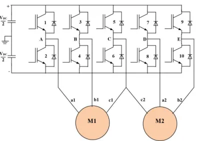
The typical connection of the five leg voltage source inverter for two three-phase induction motors is shown in Figure 1 Each of the leg consists of two switches with a total number of ten switches altogether. Inverter legs A and B are connected to M1 meanwhile D and E legs are connected to M2. In the FLI topology, one leg is used as the common leg. This common leg is shared to the both motors. In this case, leg C is chosen as the common leg. All the legs are connected to the three-phase supply termination of the motors denoted as a1,b1,c1 and a2,b2,c2 to represent M1 and M2 termination respectively.
Figure 1:Connection between five leg inverter and motors
B. Double Zero Sequence (DZS) Injection Method Configuration
ISSN (Online): 2278 – 8875
I
nternational
J
ournal of
A
dvanced
R
esearch in
E
lectrical,
E
lectronics and
I
nstrumentation
E
ngineering
(An ISO 3297: 2007 Certified Organization)
Website: www.ijareeie.com
Vol. 6, Issue 12, December 2017
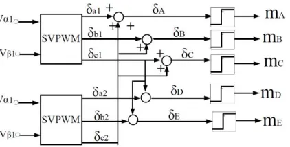
Figure 2 : Double Zero Sequence Injection Method block diagram.
Based on the principle, the first set of fundamental voltages in stationary frame is synthesized in the three-phase leg space vector modulator. This process is repeated for set 2. The output of the modulator is δ, which can be considered as the duty cycle for each three leg. The output signals of set 1 and set 2 are than summed in an appropriate manner to reduce the number of modulation signals from six to five as presented in the block diagram configuration. The summed results of output set 1 and set 2 generate modulated signal for all the five legs of the inverter as equation below:
Finally, the modulation signals of the FLI which are noted as mA, mB, mC, mD and mE respectively are compared to the carrier signal to generate output voltage of the FLI. The FLI then gives the input to the induction motors as per the switching states and angles of the IGBT, which in turn produces input voltages across the line terminals of the motor. This leads to a precise control of the speed and torque of the two induction motors.
C. Three phase Induction motor model
The MATLAB/Simulink model of three-phase induction motor is developed based on the following equations in synchronous reference frame [1].
Stator voltage equation:
Vds=RsI̅ds+ -ωs ds Vqs=RsI̅qs+ -ωs ds
Rotor voltage equation:
dr=0=Rs ̅qs+- - (ωs- ωr) qr qr=0=Rs ̅qr+ -(ωs-ωr) dr
Stator flux equation:
ds= LsI̅ds+LmI̅dr qs= LsI̅qs+LmI̅qr
Rotor flux equation:
dr= LmI̅ds+LrIdr ̅ qr= Lm qs̅ +LrI̅qr
Torque equation:
ISSN (Online): 2278 – 8875
I
nternational
J
ournal of
A
dvanced
R
esearch in
E
lectrical,
E
lectronics and
I
nstrumentation
E
ngineering
(An ISO 3297: 2007 Certified Organization)
Website: www.ijareeie.com
Vol. 6, Issue 12, December 2017
III. FOC AND DTC CONFIGURATION IN FLI SYSTEM
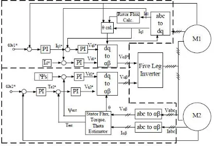
The block diagram of two induction motors applying FOC and DTC schemes in a FLI system is illustrated in Figure 3. The FOC scheme is applied to control motor M1 while the DTC scheme is applied to the motor M2. Both of the schemes are used to control the variable speed demand for forward and reverse direction. In a single three-phase motor with single inverter application, this method is proven to be able to control the motor torque and flux effectively in order to force the motor to accurately track the command regardless of the machine and load variation or disturbance.
Figure 3:Two induction motor drive in FLI system diagram
With reference to Figure 3 the indirect FOC block diagram is applied to M1. In this system, the rotating coordinate reference frame having direct axis is aligned with the rotor flux vector that rotate at the stator frequency. This results in a decoupling of the variable so that the flux and torque can be separately controlled by the direct axis stator current, id and the quadrature axis stator current, iq component. Based on the rotor voltage quadrature axis equation of induction motor, the rotor flux linkage can be estimated using this formula;
r=
Where, is the rotor time constant
The slip frequency is obtained from the rotor voltage direct axis equation:
sl=
The rotor flux position, for coordinate transform is generated from the integration of root speed and slip frequency.
Θ
e=∫
r+ω
slThe reference torque current, iq* is generated from the error of speed demand, ωr1* and actual measure speed, ωr1
with the speed PI controller. Then the iq* is compared with the actual torque current component, iq and this gives the torque current error. This error is processed to generate the reference voltage torque component, Vq*. On the other hand, the reference flux component current, id* which has been set earlier to a constant value is compared with the actual values of this variable, id. The error signal is applied to PI controller to generate the command values of flux voltage components, Vd*. These reference voltages are then transformed into stationary reference frame voltage by dq to αβ transformation for SVPWM modulation process.
Meanwhile the DTC method block diagram is used to control the speed of M2. The value of stator voltage and stator current in stationary reference can be calculated from equation below:
V
sα=
√
(2Sa-Sb-Sc)
V
sβ=
√
(S
b-S
c)
V
sα=
ISSN (Online): 2278 – 8875
I
nternational
J
ournal of
A
dvanced
R
esearch in
E
lectrical,
E
lectronics and
I
nstrumentation
E
ngineering
(An ISO 3297: 2007 Certified Organization)
Website: www.ijareeie.com
Vol. 6, Issue 12, December 2017
V
sβ=
√
(Isb-Isc)
Torque is derived from the motor equation in stationary reference form given is:
=
∫
(V
−
I R
) dt
T =
(
I
−
I
)
The difference between speed reference, ωr2* and speed feedback is amplified in the speed control amplifier of the PI controller and the output of the speed controller serves as the reference input to the torque component loop. The reference torque, Te* is compared with the estimated torque component, 4:5 to produce torque error. This error is amplified through PI controller to generate the reference voltage torque component Vsq*. The stator flux component, |ψs| is set to a constant value and compared with the estimated value for stator flux 9: and is converted to direct axis voltage demand, Vd*. Then, both voltage components in rotating reference frame are transformed to the stationary reference frame by dq to αβ transformation. The second set of reference voltage vector is synthesized through the modulation of the FLI.
IV. SIMULATION RESULT OF SPEED CONTROL OPERATION
A. Parameter Set-up for FOC and DTC and FOC
The induction motor is fed by a PWM voltage source inverter which is built using a Universal Bridge Block. The speed control loop uses a proportional-integral controller to produce the flux and torque references for the DTC & FOC block. The DTC/ FOC block computes the motor torque and flux estimates and compares them to their respective reference. The comparators outputs are then used by an optimal switching table which generates the inverter switching pulses. Motor current, speed, and torque signals are available at the output of the block.
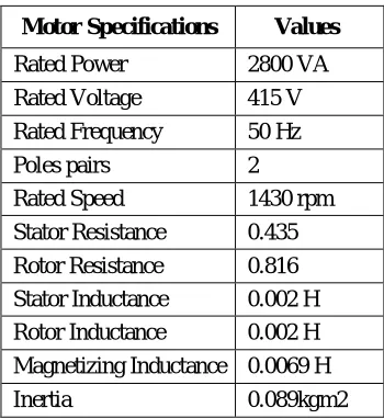
Table I Induction motor parameters
Motor Specifications Values
Rated Power 2800 VA Rated Voltage 415 V Rated Frequency 50 Hz
Poles pairs 2
Rated Speed 1430 rpm Stator Resistance 0.435Ω Rotor Resistance 0.816Ω Stator Inductance 0.002 H Rotor Inductance 0.002 H Magnetizing Inductance 0.0069 H
Inertia 0.089kgm2
B. DTC Simulation Results
ISSN (Online): 2278 – 8875
I
nternational
J
ournal of
A
dvanced
R
esearch in
E
lectrical,
E
lectronics and
I
nstrumentation
E
ngineering
(An ISO 3297: 2007 Certified Organization)
Website: www.ijareeie.com
Vol. 6, Issue 12, December 2017
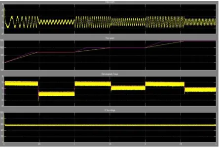
induction motor takes heavy current during starting. Then as the system becomes stable the current reduces to the stable value. Then the variable speed and torque requirement is fed to the controller and the current as well as electromagnetic torque varies. The pink lines are the reference values and the yellow ones are the actual measured parameters.
Fig. 4 DTC Simulation results
C. Vector Control Simulation Results
Figure 5 shows the simulation results of Vector control method which is applied to motor of 3 HP, the parameters of which are mentioned in the modeling section. The analysis is done on the basis of speed and torque references as mentioned in the modeling section. The parameters for analysis of FOC are the same as that of DTC as the comparison has to be done on a common platform. As seen from the figure 5 for the reference speeds and torques the variation of stator current actual rotor speed and the DC bus voltage is observed. It is clear from the figure that initially as the rotor speed up for the reference speed of 700 RPM; the stator current is very high. This is due to the fact that the induction motor takes heavy current during starting. Then as the system becomes stable the current reduces to the stable value. Then the variable speed and torque requirement is fed to the controller and the current as well as electromagnetic torque varies.
Fig. 5 Vector Control Simulation results
ISSN (Online): 2278 – 8875
I
nternational
J
ournal of
A
dvanced
R
esearch in
E
lectrical,
E
lectronics and
I
nstrumentation
E
ngineering
(An ISO 3297: 2007 Certified Organization)
Website: www.ijareeie.com
Vol. 6, Issue 12, December 2017
S p ee d ( rp m )
some of the comparison aspects on the other. In general each technique has advantages and disadvantages, so we cannot say that one of them is completely better than the other but that is based on particular application.
D. Parameter Set-up for combined FOC and DTC
Simulations have been carried out for the two motor controls for the FLI by using SVPWM method. A dedicated speed range and torque load is applied to understand the performances of the FOC and DTC method with the FLI through the motors performances. Two similar types of three- phase induction motors are used in the simulation studies and details about the motor parameters are shown in Table I.
Based on the two induction motor drives fed by a single inverter principle, the summed voltage requirement of both motors must be within the DC bus voltage supply. The FLI is supplied by using 537V DC supply and carrier frequency is set at 3 kHz. Thus, this simulation is performed with a few speed ranges for forward and reverse operation by abiding to this principle in order to understand the speed behaviors. The analysis is limited to the half rated speed and half rated load for performance comparison. The motors are set to follow the speed operating demand and external torque load applied as follows:
M1-400 rpm is applied from zero to 0.4s, and then the speed is increased to 600rpm until it reaches 1s and suddenly step changed to -750rpm at 1s until it reaches 2s.
Torque load 1(TL1): 3Nm external load torque is applied to the M1 from 0.6s to 1.5s
M2-400 rpm is set from zero to 0.4s, and then the speed is increased to 750rpm until it reaches 1s and suddenly step changed to -750rpm at 1s until it reaches 2s.
Torque load 2(TL2): 5Nm external load torque is applied to M2 from 0.6s to 1.5s
By referring to the vector control block diagram in Figure 1, three PI controllers are used for the speed, torque and flux controlled for FOC and DTC. All the PI controllers are tuned manually to produce a periodic speed response with minimum settling time to the applications of 50% rated speed command under no load conditions with rated inertia. Table III shows the PI controller parameters for speed, torque and flux components.
Table III. Speed, torque and flux controller parameters
PI controller FOC PI valueDTC PI Value
Speed Controller Kp=2.55 Ki=80 Kp=25 Ki=50 Torque Controller Kp=45 Ki=90 Kp=150 Ki=5000
Flux Controller Kp=25 Ki=60
Kp=440 Ki=70000
E. Combined DTC and FOC Simulation Results
The performance investigation of the FOC and DTC method fed the FLI is conducted to understand the behavior of the motors under different speed command change, load disturbance, steady state stability and transient response.
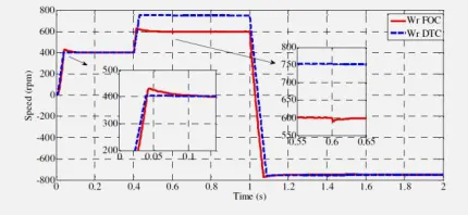
Fig. 6 M1 and M2 Speed Response
ISSN (Online): 2278 – 8875
I
nternational
J
ournal of
A
dvanced
R
esearch in
E
lectrical,
E
lectronics and
I
nstrumentation
E
ngineering
(An ISO 3297: 2007 Certified Organization)
Website: www.ijareeie.com
Vol. 6, Issue 12, December 2017
show the ability of the FLI to independently control the motors using combined FOC and DTC method. At -750rpm demand, the result shows the ability of the system to perform at 50% voltage utilization factor with FLI. Further analysis of the speed response during 400rpm speed and no load demand conclude that the DTC method produced lower percent overshoot (%OS) and faster speed response compared to FOC with about 1%OS and 8%OS respectively. Both methods are able to absorb different external loads applied with a minor speed drop at 0.6s to the motors and before recovering in a few milliseconds.
Fig. 7: M1 and M2 Torque Characteristic Performances
Based on the torque characteristics in Figure 5, DTC has experienced lower electrical torque response compared to the FOC which are about 12Nm and 16Nm respectively. In this case, the torque component is limited to 10Nm for DTC or 10A for FOC. In DTC, torque is directly controlled while in FOC the torque is controlled by the torque current component. The torque can be analyzed during no load condition at 400rpm, DTC experienced 0.3Nm while FOC shows 0.5Nm. Overall, torque analysis has shown the FOC has a higher torque ripple compared to DTC.
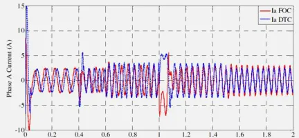
Figure 7 depicts phase A current of M1 and M2. Based on the current responses, the higher currents occurred during start up condition, during speed reversal and when external loads were applied. From the torque response, higher load condition experience higher stator current and vice versa. This is in line with the motor operation principle.
Fig. 8 M1 and M2 Phase A stator current characteristic performances
V. CONCLUSION
ISSN (Online): 2278 – 8875
I
nternational
J
ournal of
A
dvanced
R
esearch in
E
lectrical,
E
lectronics and
I
nstrumentation
E
ngineering
(An ISO 3297: 2007 Certified Organization)
Website: www.ijareeie.com
Vol. 6, Issue 12, December 2017
REFERENCES
[1] M.H.N. Talib, Z.Ibhrahim, N.Abdul Rahim, N.Mohd Yaakop, “Development of Combined Vector & Direct Torque Control methods for independent two Induction motor drives”, in 2012 IEEE International Power Engineering & optimization conference(PEOCO20120), Melaka, Malaysia, 6-7 June 2012
[2] Masahiro Taniguchi, Takashi Yoshiunaga, Kauki Matsuse, “Speed-sensor less Vector control of Parallel-connected Multiple Induction Motor Drives with Adaptive Rotor Flux observers”. Department of Electrical and Electronic Engineering
[3] Fathalla Eldali , “A comparative study between vector control and direct torque control of induction motor and partial fulfilment of the requirements For the Degree of Master of Science Colorado State University Fort Collins, Colorado ,Fall 2012
[4] M.H.N. Talib, Z.Ibhrahim, N.Abdul Rahim, N.Mohd Yaakop, “Speed performance of SVPWM direct torque control for five leg inverter served dual threephase induction motor” ”, in 2012 IEEE International Power Engineering & optimization conference (PEOCO20120), Melaka, Malaysia, 6-7 June 2012