Available online: http://internationaljournalofresearch.org/ P a g e | 546
Single-PhaseHigh-Power Fuel Cell Converter With Direct
Double-Frequency Ripple Current Control
Poolagandham Annapoorna M.Tech, PEED Ravula Srikanth Asst. Professor, EEE
Sahasra College Of Engineering For Women, Warangal
ABSTRACT:This project proposes a direct double-frequency ripple current control in a single-phase high-power fuelcell converter that can accomplish low-frequency ripple-free input current without using large electrolytic capacitors.Such a ripple current may reduce fuel cell life span. It tends to decrease the fuel cell output capacity because the fuelcell controller trips under instantaneous over-current condition. In this proposed method the content of ripples incurrent is reduced without requirement of extra switching devices. A fuel cell power system that contains a dc–acinverter tends to draw an ac ripple current at twice the output frequency. Such a ripple current may reduce input celllifespan an advanced active control method is proposed to incorporate a current control loop in the dc–dc converter forripple reduction.
KEYWORDS-Current-fed three-phase dc–dc converter, direct double-frequency ripple current control, electrolyticcapacitor free, fuel cell.
I. INTRODUCTION
Fuel cells are recognized as a future source of generating energy due to their efficient and clean energy characteristics,they produce low-varying dc voltage in the range of 30 to 60V for static power application such as residential usage.For static fuel cells, the power conditioning system consists of a low-voltage fuel cell as the primary source, a dc/dcconverter to accomplish isolated high voltage, and a dc/ac inverter to connect commercial ac voltage. A dc/ac invertersupplies power into a 220V ac utility, an isolated dc/dc converter has to convert low varying dc voltage to high constantdc voltage about 370V. Therefore, a dc/dc converter with a high voltage ratio is needed, and a transformer is
normallyemployed for boosting voltage as well as isolation. However, high leakage inductance in the transformer leads tovoltage spikes and electromagnetic noise. In order to accomplish a high voltage ratio while limiting the overshoot in theturn-off voltage produced by the leakage inductance, a current-fed dc/dc converter with an active clamp has beenhosted in the push–pull topology and full-bridge topology for all single–phase application. In addition, a soft-switchingactive clamp scheme has been suggested to minimize turn-off losses in the clamp switch. These converters have beendisplayed to perform pretty well, but the single-phase circuits face severe components stress and degraded efficiencyfor higher power levels.
Available online: http://internationaljournalofresearch.org/ P a g e | 547 design enableshigh power operation, modularity,
interleaved operation withlower current and voltage ripples, (N+1) redundancy, etc.In some high and medium power applications, when singlephase converter implementation is complicated, three-phaseDC-DC converter can be considered as a suitable solution. Athree-phase isolated DC-DC converters were first proposed toovercome limitations of a single-phase counterparts in [12].This approach does not provide as many advantages as multiphase parallel converters, while it requires only a singleisolation transformer and thus can provide lower cost andhigher power density.
Recently, numerous three-phase CF interface converterswere introduced for fuel cell applications . Fuel cellsrelate to demanding application field, since they typicallyfeature the highest output power and current at the lowest inputvoltage. It means that CF converter should provide the highestDc voltage gain at the highest input current. Therefore,majority of three-phase CF interface converters proposedrecently feature soft-switching to achieve high efficiency. Mostof them utilize the active clamping circuits at either the inputside, or the output side.
To achieve a high step-up gain with high efficiency in non-isolated applications, a high step-up method basedon isolated-type converters is hosted. By piling the secondary side of an isolated converter in addition to its primaryside, a high step-up conversion ratio and distributed voltage stress can be achieved. Moreover, a careful selection of anisolated converter can deliver zero-voltage switching (ZVS), continuous input current and reduced reverse recovery ondiodes. A conventional voltage double rectifier boost-integrated half-bridge converter, the proposed converter satisfiesall these features, which make appropriate for high step-up applications.
DC-DC converter: In many industrial applications, it is required to converter a fixed dc source into a variable voltage dc source.A dc-dc converter converts directly from dc-dc and simply known as a dc converter. A dc converter can be consideredas dc equivalent to an ac transformer with a endlessly variable turn’s ratio. Like a transformer, it can be
used to stepdown or step up a dc voltage source. Dc converters can be used as switching-mode regulators to convert a Dc voltage,normally unregulated to a regulated dc o/p voltage. This regulation is normally achieved by PWM at a fixed frequencyand the switching device is normally BJT MOSFET IGBT. The designer can select the switching frequency bychoosing the value of R, L, and C of frequency oscillator.
II. SYSTEM MODELS
A. Proposed Fuel Cell System Description
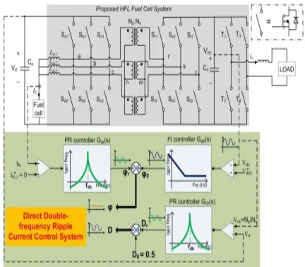
Fig. 1 shows the proposed two-stage HFL-based high-powerfuel cell system. The system consists of a current-fed threephase HFL converter with an isolated Y-Y connected highfrequency (HF) transformer and an inverter. The three-phaseHFL converter power flow is controlled by the phase shift angleϕ between the active switches on the low-voltage side (LVS)and the high-low-voltage side (HVS). The converter can be operatedeither in the boost mode or in the buck mode. system.The major features of this three-phase HFL converter havebeen studied. However, the method to reduce theinput double-frequency ripple current caused by the inverterload has not been discussed.
Available online: http://internationaljournalofresearch.org/ P a g e | 548 Fig. 1.(a) Proposed two-stage HFL-based high-power
fuel cell power conditioning system.(b)Equivalent ripple circuit model of the proposed fuel cell system.
B. Equivalent Ripple Circuit Modeling of the Proposed Fuel Cell System
Fig. 1(b) shows the equivalent ripple circuit model of theproposed fuel cell system. Vfc is the fuel cell stack voltage. Iffuel cell current has negligible low-frequency ripple current, Vfcis the constant voltage. The dc–dc converter can be simplifiedas an ideal dc transformer since its switching frequency is muchlarger than the system ripple frequency. The inverter loadis modeled as a double-frequency pulsation current source idc.As shown, both the LVS dc-bus voltage Vd and the HVS dc-busvoltage Vdc have the relatively large voltage swing. This controlis designed based on the following three aspects.
o First, large voltage variation of Vdc leads to small HVS dc-bus capacitor Cs, which makes it viable to replace the electrolytic capacitor with a film capacitor. This has already been explained in [15].
o Second, if real-time balancing of transformer primary- and secondary-side voltages can be maintained by synchronizing Vd with primary-referred Vdc, the three-phase HFL converter can always maintain the ZVS operation. This will be further explained in the next section.
o Third, voltage variation on both LVS and HVS dc buses makes both the primary- and secondaryside capacitive energy sources (Cp and Cs, as shown in the circuit in Fig. 2) to
provide the ripple energy required bythe inverter load.
III. PROPOSED CONVERTER TOPOLOGY AND OPERATION ANALYSIS
This paper presentstwo-stageHFL-basedhigh-power fuel cell system shows in Fig 2. The system consists of acurrent-fed 3- phase HFL converter with an isolated Y-Y connected high- frequency (HF) transformer and an inverter.Thephaseshiftangleϕ
controls the three-phase HFLconverterpowerflowbetween the active switches on the low-voltageside (LVS) andthehigh-voltageside(HVS).Theconvertercanbefunctioned ther in the boost mode or in the buck mode.In this proposed method, the converter is operated in boost mode for fuel cell application. The boost function isachieved by the dc inductors (Ldc1, Ldc2, and Ldc3) and three half-bridges on the LVS. The leakage inductors (Ls1,Ls2, and Ls3) are the energy transfer element for eachphase. This research focus is to study the direct double-frequencyripple current control of this three-phase HFL converter while connecting a single-phase inverter load.
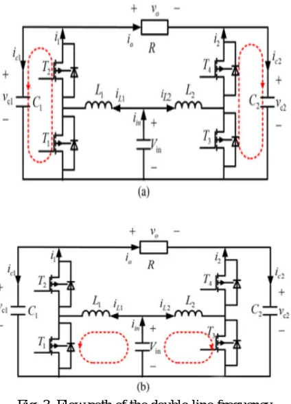
Available online: http://internationaljournalofresearch.org/ P a g e | 549 Fig. 3. Flow path of the double-line-frequency
current component of the inverter. (a) With waveform control. (b) Without waveform control.
A. Effect of Capacitance Tolerance
Since the values of the capacitors C1 and C2 can affect thecomputation of the proposed waveform control, the effect of using a difference capacitance from that originally assumed in thecomputation on the control performance must be investigated.First, the parameters C1 and C2 are chosen asC1 = C2 = 15 μF for the voltage reference calculation adoptedin waveform control. Then, a circuit simulation with C1 andC2 in the power stage varying from 5 to 25 μF is performed.It is observed that alarger deviation of the capacitor value from the assumed valueof 15 μF leads to a poorer compensation of the double-linefrequency component. Yet, as the tolerance of the film capacitoris usually less than 10%, the effect of capacitance tolerance onthe compensation capability is small (less than 8.19%), as given.
B. Further Remarks
The adoption of the proposed waveform control method tomitigate the low-frequency input current ripple will alter theoriginal behavior of the differential inverter without waveformcontrol. The following are important points to consider in terms of the adoption of waveform control:
1) there is no change in the desired ac output voltage eventhough the voltages of the capacitors themselves arealtered;
2) the energy stored by the capacitors, which is a function ofthe voltages, is made up of a dc component and a doubleline-frequency component;
3) DC energy is stored by the two capacitors while theysupply ac energy to the output load. Consequently, thelow-frequency power pulsation caused by ac output isabsorbed by the capacitors while the fuel cells kept aconstant supply of dc power to the capacitors;
4) as the capacitor voltages vc1 and vc2 are much higher thanthe dc input voltage vin, the energy transfer will occurwhen the voltage fluctuation on C1 and C2 is increased.
An interesting point to take note is that since the capacitorvoltages can be large without affecting the desired ac outputvoltage, both capacitors can be minimized without increasingthe ripple voltage on the dc input. The advantage is that filmcapacitors can be used instead of electrolytic capacitors to improve reliability. The practical limit is the voltage rating of thecapacitors.
IV. SIMULATION RESULTS
Available online: http://internationaljournalofresearch.org/ P a g e | 550 final DC voltageis obtained at the output side of the
circuit.
Fig .4Matlab/simulinkdiagram of two-stage
HFL-based high-power fuel cell power conditioning
system.
Fig .5 Controller subsystem
Fig .6Input VOLTAGE (VTDC)
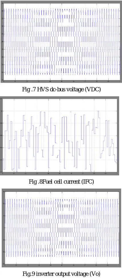
Fig .7 HVS dc-bus voltage (VDC)
Fig .8Fuel cell current (IFC)
Available online: http://internationaljournalofresearch.org/ P a g e | 551 Fig. 10
V. CONCLUSION
Three-phase HFL-based fuel cell power conditioning system that can accomplish low-frequency ripple-free input currentby making use of direct double-frequency ripple current control. The proposed method can make full exploitation ofcapacitive ripple energy sources.Thecontrol system design based on the small-signal model hasbeen analyzed in detail. To directly remove the fuel cellcurrent double-frequency ripple, a PR controller is developedto achieve an extra high control gain at 120-Hz resonant frequency. This controller generates the virtual high impedancethat can block the ripple energy propagation from inverter loadto fuel cell stack, and it also eliminates the trouble fromvaried duty cycle.
REFERENCES
[1] M. W. Ellis, M. R. Von Spakovsky, and D. J. Nelson, “Fuel cell systems:Efficient, flexible energy conversion for the 21st century,” Proc. IEEE,vol. 89, no. 12, pp. 1808–1818, Dec. 2001.
[2] M. C. Williams, J. P. Strakey, and S. C. Singhal, “US distributed generation fuel cell program,” J. Power Sources, vol. 131, no. 1/2, pp. 79–85,May 2004
[3] Shih-Jen Cheng; Yu-Kang Lo; Huang-Jen Chiu; Shu-Wei Kuo, "HighEfficiency Digital-Controlled Interleaved Power Converter for HighPower PEM Fuel-Cell Applications," IEEE Transactions on IndustrialElectronics, vol.60, no.2, pp.773-780, Feb. 2013
[4] Changrong Liu; Johnson, A.; Jih-Sheng Lai, "A novel three-phase highpower soft-switched DC/DC converter for low-voltage fuel cellapplications," IEEE Transactions on Industry Applications, vol.41, no.6,pp.1691-1697, Nov.-Dec. 2005
[5] Younghoon Cho; Jih-Sheng Lai, "High-Efficiency Multiphase DC–DCConverter for Fuel-Cell-Powered Truck Auxiliary Power Unit," IEEETrans. Vehicular Technology, vol.62, no.6, pp.2421-2429, July 2013
[6] Mason, A.J.; Tschirhart, D.J.; Jain, P.K., "New ZVS Phase ShiftModulated Full-Bridge Converter Topologies With Adaptive EnergyStorage for SOFC Application," IEEE Transactions on PowerElectronics, vol.23, no.1, pp.332-342, Jan. 2008
[7] Rathore, A. K. "Interleaved soft-switched active-clamped L–L typecurrent-fed half-bridge DC–DC converter for fuel cell applications," Int.J. of Hydrogen Energy, vol. 34, no. 24, pp. 9802-9815, 2009.
[8] Pan Xuewei; Rathore, A.K., "Novel Interleaved BidirectionalSnubberless Soft-Switching Current-Fed Full-Bridge Voltage Doublerfor Fuel-Cell Vehicles," IEEE Transactions on Power Electronics,vol. 28, no. 12, pp. 5535-5546, Dec. 2013
[9] Zhan Wang; Hui Li, "A Soft Switching Three-phase Current-fedBidirectional DC-DC Converter With High Efficiency Over a WideInput Voltage Range," IEEE Transactions on Power Electronics, vol.27,no.2, pp.669-684, Feb. 2012
[10] Kong, X.; Khambadkone, A.M., "Analysis and Implementation of aHigh Efficiency, Interleaved Current-Fed Full Bridge Converter for FuelCell System," IEEE Transactions on Power Electronics, , vol.22, no.2,pp.543-550, March 2007
Available online: http://internationaljournalofresearch.org/ P a g e | 552 [12] Prasad, A.R.; Ziogas, P.D.; Manias, S.,
"Analysis and design of a threephase offline DC-DC converter with high-frequency isolation," IEEETrans. Industry Applications, vol.28, no.4, pp.824-832, Jul/Aug 1992.
Authors: