Direct Torque and Flux Control of Induction
Motor Using Intelligent Technique
G.Kanimozhi
1, K. Subbulakshmi*
2Assistant Professor, Dept. of ECE, Jerusalem College of Engineering, Chennai, Tamil Nadu, India 1
Assistant Professor, Dept. of ECE, Bharath University, Chennai, Tamil Nadu, India2
* Corresponding Author
ABSTRACT:This paper, presents speed control and torque control method for Induction motor, by using DTC based fuzzy logic, it is applied in switching select voltage vector .The comparison with conventional direct torque control (DTC), show that the use of the DTC_FL , reduced the torque, stator flux, and current ripples. The validity of the proposed methods is confirmed by the simulative results
KEYWORDS: Induction Motor Model, Direct torque control (DTC) of Induction Motor, FLC control
1. INTRODUCTION
Induction motor drives controlled by Field Oriented control (FOC) have been till now employed in high performance industrial applications, has achieved a quick torque response, and has been applied in various industrial applications instead of dc motors [1-3] .It permit independent control of the torque and flux by decoupling the stator current into two orthogonal components FOC[1-3], however, is very sensitive to flux, which is mainly affected by parameter variations. It depends on accurate parameter identification to achieve the expected performance. During the last decade a new control method called DTC (Direct Torque Control) has been developed for electrical machines. DTC principles were first introduced by Depenbrock and Takahashi [1-2]. In this method, Stator voltage vectors is selected according to the differences between the reference and actual torque and stator flux linkage. The DTC method is characterised by its simple implementation and a fast dynamic response. Furthermore, the inverter is directly controlled by the algorithm, i.e. a modulation technique for the inverter is not needed [1-4].However if the control is implemented on a digital system (which can be considered as a standard nowadays), and the actual values of flux and torque could cross their boundaries too far.
II. MODEL OF THE INDUCTION MOTOR
The model of the IM is presented as follows:
With:
III. DTC PRINCIPL
The electromagnetic torque is proportional to the vector product of flux stator and rotor,
it is expressed by [6]-[7]:
Where:
IV. CONTROL STRATEGY OF DTC
The choice of the vector Vs depends on:
- If V0 or V7 is selected, the rotation of flux is stopped; the torque decreases whereas the module of flux remains unchanged.
Figure 2.Voltage space vector and sector location
The voltage vector table in figure 2 receives the input signals HΨ, HCe, and S and generates the appropriate control voltage vector (switching states) for the inverter according to the Table 1.
Table 1: Status of switches
The dynamic torque is generally faster than the flux. Therefore, the use of a comparator with two level hysteresis-bands is justified in order to adjust the torque and minimize the frequency switching average [7].
V. FUZZY SPEED CONTROLLER
The motor speed can be controlled indirectly by controlling the torque with a fuzzy controller. Fuzzy logic is based on the theory of fuzzy sets developed by Zadeh [9]. This is an extension of the classical theory for the incorporation of fuzzy set. The proposed fuzzy controller has two inputs and one output as described in Figure 5.
Figure 5: structure of the fuzzy controller
VI. DTC BASED FUZZY LOGIC
The principle of direct torque control using fuzzy logic (FDTC). The fuzzy controller is designed to have three fuzzy state Variables and one control variable for achieving direct torque Control of the induction machine[8][9][12], there are two variable input fuzzy logic controllers, Speed error membership function, change in Speed error membership function respectively the output it is the Current reference membership function. Fig (5) shows the structure of fuzzy speed controller.
6.1 CURRENT REFERENCE SETTING
In this part, current reference is determined for the three phase’s currents hysteresis control. The FLC generates current reference changes (dIref ), based on speed error (eN = Nref-Nactual) and its change (ceN = eN(k+1)-eN(k)). dIref is integrated to achieve current reference. Thus, the limits for the universes of the antecedents and consequents were initially settled.
The error has its minimal value when the motor speed has nominal value, +105rad /s, and is inverted to -105 rad /s. So, we have eN =Nref-N= (--105) -(+-105) =-310 rad /s. The maximum value, +310, is obtained in the opposite situation.
The maximum torque obtained with the motor nominal current (5A) is 7 Nm, thus which we can calculate the maximum absolute value for ceN:
ceN = eN(k) - eN(k - 1) 10
= (Nref - N (k)) - (Nref - N(k - 1)) 11
= -(N (k) -N (k - 1)) = -dN 12
J(dN /dt)= 13
dN=( dt/J) 14
CeN=( dt/J) 15
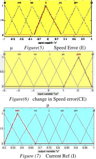
So, the initial limits for the universe of the antecedents and consequents were the following: eN : -310 to + 310 rad /s
ceN : -24 to + 24 rad/s/ s dIref : .5 to 1 (Amp)
μ Figure(5) Speed Error (E)
Figure(6) change in Speed error(CE) μ
Figure (7) Current Ref (I)
6.2 RULE BASE
FE, FdE, FdU are gains called "scale factor”. They can change the sensitivity of the controller without changing its structure. The fuzzy controller is composed of three blocks: fuzzification, rule bases, and defuzzification.[10,11]show the function of membership of each input signals (E,dE). The fuzzy subsets are as follows:NB(Negative Big), Nm (Negative Medium), NS(Negative Small), Z (Zero), PS (Positive Small),PM (Positive Medium), PB (Positive Big). There are 7 fuzzy subsets for each variable, which gives 7 * 7 =49 possible rules, where a typical rule is: "If E(pu) is PS and dE(pu) is PM Then dU (pu) PB". Table 2 shows the rule base of fuzzy controller.
e/e NB NM NS ZE PS PM PB
NB NB NB NB NM NM NS ZE
NM NB NB NM NS NS ZE PS
NS NB NM NS NS ZE PS PM
ZE NM NS NS ZE PS PS PM
PS NM NS ZE PS PS PM PB
PM NS ZE PS PS PM PB PB
PB ZE PS PM PM PB PB PB
VII. RESULTS AND DISCUSSION
To study the performance of the fuzzy logic switching table with direct torque control strategy, the simulation of the system was conducted using SIMULINK and Fuzzy logic toolbox[13]. Simulation results for a DTC system when controlling the induction machine is following parameters:
PN = 15KW, Vn = 230V, Fn = 50Hz , Rs =2.89ohm, Rr=2.39ohm, P=6, Ls=Lr=0.225H, Lm=0.214H, J=0.005kgm.
The Sampling period of the system is 2microsecs.To compare with C_DTC, FLDTC for IM are simulated. In two cases, the dynamic responses of speed, flux, torque and stator current for the starting process with [5, 7, 3] Nm load torque applied and a constant command flux of 0.6Wbs are shown in Figure from 8 to 11 respectively. Figs.8 (a, b) shows the response of electric torque of the C_DTC, FL_DTC respectively. It can be seen that the ripple in torque with FL_DTC control is less than 0.3 Nm and with conventional direct torque control the ripple is about 2 Nm at the same operating conditions. Figs.9 (a, b) shows the response of stator flux magnitude of the C_DTC, FLDTC respectively. By FLDTC technique shown Fig 9 (b) , the stator flux are the fast response in transient state and the ripple in steady state is reduced remarkably compared with conventional DTC, the flux changes through big oscillation and the torque ripple is bigger in C_DTC .Figs 10.1.(a and b) show the steady state current response of the C-DTC and FLDTC, it shows the FLDTC has negligible ripple in stator current and a nearly sinusoidal wave form while as with conventional DTC the stator current has considerably very high ripple. Fig 11(a,b)shows the speed response of the C-DTC and FLC-DTC. it shows the speed response of FLC-DTC is very quick compare to C_C-DTC ,it can be seen that the speed settling time of (FLDTC) is about 3.47 secs ,but C_DTC takes 4.27secs at the same operating condition.
Fig.8a. Electromagnetic torque Response C DTC
Fig.9a. The stator flux Magnitude C_DTC
Fig.9 b. The stator flux Magnitude FLDTC
Fig.10 b. the stator current FLDTC
Fig 11a Speed vs time characteristics C_DTC
Fig 11b Speed vs time characteristics FLDTC
VIII. CONCLUSION
command flux optimization scheme has been proposed to reduce the torque ripple. The optimization was tested using simulation. The results show a reasonable improvement by flux optimization. The main improvements shown are: • Reduction of torque and current ripples in transient and steady state response.
•.Swift speed response
• Fast stator flux response in transient state
REFERENCES
[1]. Takahashi, T. Noguchi, ″A new quick response
and high-efficiency control strategy of induction motor″, IEEE Trans. On IA, Vol.22, N°.5, Sept/Oct 1986, PP.820-827.
[2]. M. Depenbrock, ″Direct self – control (DSC) of inverter – fed induction machine″, IEEE Trans. Power Electronics, Vol.3, N°.4, Oct 1988, PP.420-829.
[3] A Book by “Modern Power Electronics and AC Drives”, by Bimal K. Bose Pearson Education Pte.Ltd.
[4]. D. Casadei, F. Profumo, G.Serra and A.Tani, ″FOC and DTC: Tox Viable Schemes for induction Motors Torque Control″, IEEE Trans. Power Electronics. On PE, Vol.17, N°.5, Sept2002,
[5]. D. Casadei and G.Serra, ″Implementation of direct Torque control Algorithme for Induction Motors Based On Discrete Space Vector Modulation″, IEEE Trans. Power Electronics. Vol.15, N°.4, JULY2002,
[6]. A.A.Pujol, ″Improuvment in direct torque control of induction Motors″, Thèse de doctorat de L’UPC, November 2000
[7]. R.Toufouti ,H.Benalla, and S.Meziane ″Three-Level Inverter With Direct Torque Control For Induction Motor″, World Conference on Energy for Sustainable Development: Technology Advances and
Environmental Issues, Pyramisa Hotel Cairo - Egypt, 6 - 9 December 2004. [8]. JIA-QIANG YANG, JIN HUANG ″ A New
Full-Speed Range Direct Torque Control Strategy for Induction Machine″, Proceedings of the Third International Conference on Machine Learning andCybernetics, Guangzhou, 26-29 August2004
[9]. R.Toufouti S.Meziane ,H. Benalla, “Direct Torque Control for Induction Motor Using Fuzzy Logic” ICGST Trans. on ACSE, Vol.6, Issue 2, pp. 17-24, June, 2006.
[10]. Jia-Qiang Yang, Jin Huang, ″Direct Torque Control System for Induction Motors With Fuzzy Speed Pi Regulator″ Proceedings of the Fourth International Conference onMachine Learning and Cybernetics,
Guangzhou, 18-21 August 2005.
[11]. Hui-Hui Xia0, Shan Li, Pei-Lin Wan, Ming-
Fu Zhao, ″Study on Fuzzy Direct Torque Control System″, Proceedings of the Fourth International Conference on Machine Learning and Cybernetics, Beijing, 4-5 August 2002.
[12]. Ji-Su Ryu, In-Sic Yoon, Kee-Sang Lee and Soon-Chan Hong , ″Direct Torque Control of Induction Motors Using Fuzzy Variables
Switching Sector″, Industrial Electronics, 2001. Proceedings. ISIE 2001. IEEE International Symposium on Volume 2, Issue , 2001 Page(s):901 - 906 vol.2
[13] MALAB 7.6.0 version SIMULINK help menu
B Karthik, TVUK Kumar, Noise Removal Using Mixtures of Projected Gaussian Scale Mixtures, World Applied Sciences Journal, 29(8), pp 1039-1045, 2014.
[14] Daimiwal, Nivedita; Sundhararajan, M; Shriram, Revati; , Non Invasive FNIR and FMRI system for Brain Mapping . [15] Daimiwal, Nivedita; Sundhararajan, M; , Functional MRI Study for Eye Blinking and Finger Tapping
[16] Shriram, Revati; Sundhararajan, M; Daimiwal, Nivedita; , Effect of change in intensity of infrared LED on a photoplethysmogramIEEE Communications and Signal Processing (ICCSP), 2014 International Conference on, PP 1064-1067,2014.
[17] Kanniga, E; Srikanth, SMK; Sundhararajan, M; , Optimization Solution of Equal Dimension Boxes in Container Loading Problem using a Permutation Block AlgorithmIndian Journal of Science and Technology, V-7, I-S5,PP 22-26, 2014.