ISSN (Print) : 2320 – 3765 ISSN (Online): 2278 – 8875
I
nternational
J
ournal of
A
dvanced
R
esearch in
E
lectrical,
E
lectronics and
I
nstrumentation
E
ngineering
(An ISO 3297: 2007 Certified Organization)
Website: www.ijareeie.com
Vol. 6, Issue 6, June 2017
Analytical Comparison of Elliptical Patch and
Circular Patch Microstrip Antenna
R.K. Verma1, N.K. Saxena2, P.K.S. Pourush3
Associate Professor, Dept. of Physics, Agra College Agra, Uttar Pradesh, India1 Research Scholar, Dept. of Physics, Agra College Agra, Uttar Pradesh, India2 Associate Professor, Dept. of Physics, Agra College Agra, Uttar Pradesh, India3
ABSTRACT: In this communication a comparative analysis of elliptical patch and circular patch microstrip antenna is presented. We solve wave equation by the Mathieu Special function in combined form as well as separate (Radial and Cylindrical) form. But due to some mathematical complication we had to switch Method of Moment analysis with the help of cavity model of Elliptical elements on thin dielectric substrates support only TM modes. The far field radiation patterns in the Oblate mode are obtained for E plane and H plane.
KEY WORDS: Elliptical Patch Microstrip Array Antenna, Full Wave Analysis, Mathieu Special function, Method of Moment.
I. INTRODUCTION
Elliptical patch geometry is perhaps least analyzed regular shape geometry due to involvement of higher and complex mathematics. The theoretical treatment of the elliptical patch antenna (EPA) has been tried by various numerical techniques. The elliptical shape has several advantages like providing larger degrees of freedom and flexibility in the design, compare to the circular geometry. One of the prominent advantages is circular polarization which can be easily obtained by exciting the elliptical patch rather than rectangular or circular ones by means of the proper selection of feed position of the ellipse. To generate a circular polarization the feed point should be on a radial line positioned relative to the major axis where the positive side axis gives left-hand circularly polarized (LHCP) while the negative axis gives right-hand circularly polarized (RHCP). Furthermore, the elliptic antenna offers greater flexibility in the design by utilizing the eccentricity and the focal length to fine tune the antenna to the desired performance [1-4].
Although there have been several methods used to analyze the regular patch geometries like circular, rectangular, triangular, etc. using spectral domain analysis [12], transmission line method, cavity model, resonant equivalent circuits and the method of moments [13-14] but they had the shortcomings of degrading accuracy as the thickness of the substrate increases in case of elliptical geometry [7-11]. These numerical techniques take a significant amount of computational time, even when considering just one or two modes, thus making interactive design a difficult task. The more direct approach, Green’s function approach, which is generally used for circular and rectangular patches [15], had not been applied to the EPAbecause a computationally efficient Green’s function was not available. Though approximate solutions were devised by some researchers explained in [16] and [17], these approximations are limited to small eccentricities and have dealt with the TM11 mode only. It is, however, complicated to analyze the elliptical-patch
geometry because of its unique elliptical characteristics.
II. THEORY
ISSN (Print) : 2320 – 3765 ISSN (Online): 2278 – 8875
I
nternational
J
ournal of
A
dvanced
R
esearch in
E
lectrical,
E
lectronics and
I
nstrumentation
E
ngineering
(An ISO 3297: 2007 Certified Organization)
Website: www.ijareeie.com
Vol. 6, Issue 6, June 2017
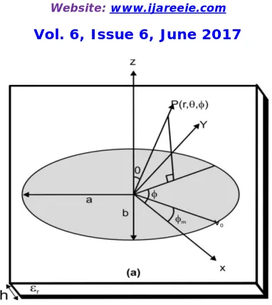
Figure 1: Geometry of microstrip rectangular patch antenna
The properties of the elliptic patch as a microstrip antenna have been investigated through extensive experimentation, though these properties have not been verified by any one general theory. In the present work we have tried two mathematical analysis (1) Full Wave Analysis and (2) Method of Moment with Cavity Model, to study the elliptical patch antenna (EPA) [16-20].
E-Plane (φ = 90o)
For Oblate Ellipse:
= = 0 (1)
= ( sin )
sin (2)
For Prolate Ellipse:
= = 0 (3)
′ = ( sin )
sin (4)
H-Plane (φ = 0o)
For Oblate Ellipse:
= = 0 (5)
= cos ( sin )
ISSN (Print) : 2320 – 3765 ISSN (Online): 2278 – 8875
I
nternational
J
ournal of
A
dvanced
R
esearch in
E
lectrical,
E
lectronics and
I
nstrumentation
E
ngineering
(An ISO 3297: 2007 Certified Organization)
Website: www.ijareeie.com
Vol. 6, Issue 6, June 2017
For Prolate Ellipse:
= = 0 (7)
′ = cos ( sin )
sin (8)
III. CALCULATION & RESULTS
The radiation patterns and radiation parameters have been plotted and calculated respectively. An ellipse patch of oblate radius 0.61 cm & prolate 0.61 cm, is printed with elements separation dx = dy = 3 cm on RT-duroid substrate of εr = 2.33 and height h = 0.165
cm.
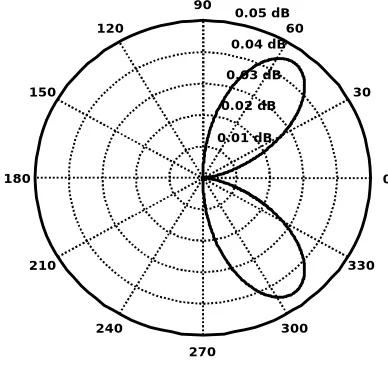
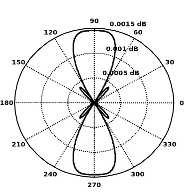
Radiation Patterns: The far field radiation patterns in the Oblate mode are obtained for E plane (φ =π/2) and H plane (φ = 00).
Figure 3: Radiation pattern of elliptical patch antenna in E-plane (φ =π/2)
Figure 4: Radiation pattern of elliptical patch antenna in H-plane (φ = 00)
0.01 dB 0.02 dB
0.03 dB 0.04 dB
0.05 dB
30
210
60
240
90
270 120
300 150
330
180 0
0.05 dB 0.10 dB
0.15 dB
30
210
60
240
90
270 120
300 150
330
ISSN (Print) : 2320 – 3765 ISSN (Online): 2278 – 8875
I
nternational
J
ournal of
A
dvanced
R
esearch in
E
lectrical,
E
lectronics and
I
nstrumentation
E
ngineering
(An ISO 3297: 2007 Certified Organization)
Website: www.ijareeie.com
Vol. 6, Issue 6, June 2017
Figure 5: Variation of R(θ,φ) for 4×4 elliptical microstrip array configuration
The total field pattern R(θ,φ) is generally obtained by the relation: R(θ,φ) = |Eθ|2 + |Eφ|2. The planar array
pattern is computed for source frequency fr = 10 GHz with progressive phase excitation bx = by = 0. The patterns of E
plane, H plane and planar array are shown in fig. 3, 4 & 5 respectively.
Radiation Parameters: All important parameters like bandwidth, directive gain, total impedance and quality factor of circular and elliptical microstrip patch antenna printed on RT-duroid has been calculated and tabulated in table 1.
Table 1: Comparison of characteristics of circular and elliptical microstrip patch antenna printed on RT-duroid
Radiation Parameters
Values
Circular Patch
Elliptical Patch
Radius /Oblate (a) 0.51 cm 0.61 cm
Prolate (b) -- 0.51 cm
Bandwidth (BW) 2.99 % 2.84 %
Directive Gain (Dg) 6.59 dB 8.37 dB
Q. Factor (QF) 13.62 14.35
Total Imped. (Zin) 124ohms 136ohms
IV. CONCLUSION
In the present work the full wave analysis has been applied to investigate the elliptical patch antenna but due to the mathematical complexities of Mathieu's and modified Mathieu's function, the analysis stopped after some even important results. The involvement of these functions makes mathematics of elliptical patch geometries extremely difficult. After this the Method of Moment has been applied with cavity model of elliptical patch antenna.
Theoretical results of elliptical patch antenna have been developed by Method of Moment analysis with the help of cavity model. Radiation field patterns for E-plane, H-plane and array configuration have been plotted for oblate
0.0005 dB 0.001 dB 0.0015 dB
30
210
60
240
90
270 120
300 150
330
ISSN (Print) : 2320 – 3765 ISSN (Online): 2278 – 8875
I
nternational
J
ournal of
A
dvanced
R
esearch in
E
lectrical,
E
lectronics and
I
nstrumentation
E
ngineering
(An ISO 3297: 2007 Certified Organization)
Website: www.ijareeie.com
Vol. 6, Issue 6, June 2017
and elliptical geometries. The calculated radiation parameters of elliptical microstrip antennas have been tabulated and compared with the results calculated for circular microstrip antenna with same configuration and frequency range.
REFERENCES
[1] Priya SS, Supriya A and Shivam BM (Mar 2017). Anslysis and Gain Enhancement og Different Shapes of Microstrip Patch Antenna. International Research Journal of Engineering and Technology. 4(3): 2379 – 2384.
[2] Kwaha BJ, Inyang ON & Amalu P (2011). The Circular Microstrip Patch Antenna – Design And Implementation. International Journal of Recent Research and Applied Studies, 18(8), 1-11.
[3] James JR, Hall PS (1989). Handbook of Microstrip Antennas. Stevenage. UK Peregrinus: 825–849.
[4] Shen LC (1981). The elliptical microstrip antenna with circular polarization. IEEE Trans. Antennas Propagat. AP-29: 90–94.
[5] Long SA, McAllister MW (1982). The impedance of an elliptical printed circuit antenna. IEEE Trans. Antennas Propagat. AP-30: 1197– 1200.
[6] Long SA, Shen LC, Schaubert DH, Farrar FG (1981). An experimental study of the circular polarized elliptical printed circuit antenna. IEEE Trans. Antennas Propagat. AP-29: 95–99.
[7] Lee KF, Chen W (1997). Advances in Microstrip and Printed Antennas, New York, Wiley.
[8] Sharma S, Bhushan B, Gupta S and Kaur P. (2013). Performance Comparison of Micro-strip Antennas with Different Shape of the Patch. International Journal of u- and e- Service, Science and Technology, 6(3), 13-22.
[9] Safa Z, Lahbib Z, Seddik BRI. (2012). Simulation of a Rectangular Patch Antenna. International Journal of Computer Science and Information Technology & Security, 2(1), 16-24.
[10] Mathur V, Gupta M. (Dec 2014). Comparison of Performance Characteristics of Rectangular, Square and Hexagonal Microstrip Patch Antennas. IEEE Conference on Reliability Infocom Technologies and Optimization, 1-6
[11] Majumder A. (2013). Rectangular Microstrip Patch Antenna Using Coaxial Probe Feeding Technique to Operate in S-Band. International Journal of Engineering Trends and Technology, 4(4), 1206 – 1210.
[12] Harrington RF (1968). Field computation by moment methods, New York, Macmillan.
[13] Shmna AK, Bhat B (1980). Spectral domain analysis of elliptic microstnp disk resonators. IEEE Trans. Microwave Theory Techn. MTT-28: 573-576.
[14] Baky MC, Deshpande MD (1985). Analysis of elliptical and circular microstrip antennas using moment method. IEEE Trans. Antennas Propagat. AP-33: 954-959.
[15] Hab‘tshy TM, Kong JA, Chew WC (1987). Resonance and radiation of the elliptic disk microstnp structure, Part I Formulation. IEEE Trans. Antennas Propugat. AP-35: 877-885.
[16] Bahl IJ, Bhartia P (1990). Microstrip Antennas, Nomood, MA, Artech House.
[17] Balanis CA (1982). Antenna theory-analysis and design, Harper and Row Publisher Inc., New York.
[18] Shen LC (1981). The elliptical micro5tnp antenna with circular polarization. IEEE Trans. Antenna & Prop. AP-29: 90-94.
[19] Long SA, McAllister MW (1982). The impedance of an elliptical printed-circuit antenna. IEEE Trans. on Antenna & Propag. AP-30: 1197-l200.